SlideShare ist ein Scribd-Unternehmen logo
1 von 12
Downloaden Sie, um offline zu lesen
IGNITION #1 - IGNITION OVERVIEW


Ignition System Overview
The purpose of the ignition system is to ignite the air/fuel mixture in the combustion chamber at
the proper time. In order to maximize engine output efficiency, the air-fuel mixture must be
ignited so that maximum combustion pressure occurs at about 10' after top dead center (TDC).

However, the time from ignition of the air-fuel mixture to the development of maximum
combustion pressure varies depending on the engine speed and the manifold pressure;
ignition must occur earlier when the engine speed is higher and later when it is lower.


                                              Page 1 © Toyota Motor Sales, U.S.A., Inc. All Rights Reserved.
IGNITION #1 - IGNITION OVERVIEW


In early systems, the timing is advanced and retarded by a governor advancer in the distributor.

Furthermore, ignition must also be advanced when the manifold pressure is low (i.e. when
there is a strong vacuum). However, optimal ignition timing is also affected by a number of
other factors besides engine speed and intake air volume, such as the shape of the
combustion chamber, the temperature inside the combustion chamber, etc. For these reasons,
electronic control provides the ideal ignition timing for the engine.


                                             Page 2 © Toyota Motor Sales, U.S.A., Inc. All Rights Reserved.
IGNITION #1 - IGNITION OVERVIEW


Electronic Spark Advance Overview
In the Electronic Spark Advance (ESA) system, the engine is provided with nearly ideal ignition
timing characteristics. The ECM determines ignition timing based sensor inputs and on its
internal memory, which contains the optimal ignition timing data for each engine running
condition. After determining the ignition timing, the ECM sends the ignition Timing signal (IGT)
to the igniter. When the IGT signal goes off, the Igniter will turn on shut off primary current flow in
the ignition coil producing a high voltage spark (7kV - 35kV) in the cylinder.

Since the ESA always ensures optimal ignition timing, emissions are lowered and both fuel
efficiency and engine power output are maintained at optimal levels.

Types of Ignition Systems
Ignition systems are divided into three basic categories:

     • Distributor.
     • Distributorless Ignition System (DLI) Electronic Ignition.
     • Direct Ignition System (DIS).

                                                Page 3 © Toyota Motor Sales, U.S.A., Inc. All Rights Reserved.
IGNITION #1 - IGNITION OVERVIEW


Essential Ignition System Components
Regardless of type the essential components are:
     • Crankshaft sensor (Ne signal).
     • Camshaft sensor (also called Variable Valve Timing sensor) (G signal).
     • Igniter.
     • Ignition coil(s), harness, spark plugs.
     • ECM and inputs.


Ignition Spark Generation
The ignition coil must generate enough power to produce the spark needed to ignite the air/fuel
mixture. To produce this power, a strong magnetic field is needed. This magnetic field is
created by the current flowing in the primary coil. The primary coil has a very low resistance
(approximately 1-4 ohms) allowing current flow. The more current, the stronger the magnetic
field. The power transistor in the igniter handles the high current needed by the primary coil.

Another requirement to produce high voltages is that the current flow in the primary coil must be
turned off quickly. When the transistor in the igniter turns off, current flow momentarily stops and
the magnetic field collapses. As the rapidly collapsing magnetic field passes through the
secondary winding, voltage (electrical pressure) is created. If sufficient voltage is created to
overcome the resistance in the secondary circuit, there will be current flow and a spark
generated.


                                                 Page 4 © Toyota Motor Sales, U.S.A., Inc. All Rights Reserved.
IGNITION #1 - IGNITION OVERVIEW


NOTE: The higher the resistance in the secondary circuit, the more voltage that will be needed
to get the current to flow and the shorter spark duration. This is important when observing the
ignition spark pattern.


IGT Signal
The primary coil current flow is controlled by the ECM through the Ignition Timing (IGT) signal.
The IGT signal is a voltage signal that turns on/off the main transistor in the igniter. When IGT
signal voltage drops to 0 volts, the transistor in the igniter turns off. When the current in the
primary coil is turned off, the rapidly collapsing magnetic field induces a high voltage in the
secondary coil. If the voltage is high enough to overcome the resistance in the secondary circuit,
there will be a spark at the spark plug.


IGC
On some ignition systems, the circuit that carries the primary coil current is called IGC. lGC is
turned on and off by the igniter based on the IGT signal.


                                               Page 5 © Toyota Motor Sales, U.S.A., Inc. All Rights Reserved.
IGNITION #1 - IGNITION OVERVIEW


Igniter
The primary function of the igniter is to turn on and off the primary coil current based on the IGT
signal received from the ECM. The igniter or ECM may perform the following functions:

     • Ignition Confirmation (IGF) signal generation unit.
     • Dwell angle control.
     • Lock prevention circuit.
     • Over voltage prevention circuit.
     • Current limiting control.
     • Tachometer signal.

It is critical that the proper igniter is used when replacing an igniter. The igniters are matched to
the type of ignition coil and ECM.


IGF Signal
The IGF signal is used by the ECM to determine if the ignition system is working. Based on IGF,
the ECM will keep power supplied to the fuel pump and injectors on most ignition systems.
Without IGF, the vehicle will start momentarily, then stall. However, with some Direct Ignition
Systems with the igniter in the coil, the engine will run.

                                               Page 6 © Toyota Motor Sales, U.S.A., Inc. All Rights Reserved.
IGNITION #1 - IGNITION OVERVIEW


IGF Signal Detection using CEMF
There are two basic methods of detecting IGF. Early systems used the Counter Electromotive
Force (CEMF) created in the primary coil and circuit for generating the IGF signal. The
collapsing magnetic field produces a CEMF in the primary coil. When CEMF is detected by the
igniter, the igniter sends a signal to the ECM. This method is no longer used.


IGF Detection Using Primary Current Method
The primary current level method measures the current level in the primary circuit. The
minimum and maximum current levels are used to turn the IGF signal on and off. The levels will
vary with different ignition systems. Regardless of method, the Repair Manual shows the scope
                                            Page 7 © Toyota Motor Sales, U.S.A., Inc. All Rights Reserved.
IGNITION #1 - IGNITION OVERVIEW


pattern or provides you with the necessary voltage reading to confirm that the igniter is
producing the IGF signal.

Lack of an IGF on many ignition systems will produce a DTC. On some ignition systems, the
ECM is able to identify which coil did not produce an IGF signal and this can be accomplished
by two methods.

The first method uses an IGF line for each coil.

With the second method, the IGF signal is carried back to the ECM on a common line with the
other coil(s). The ECM is able to distinguish which coil is not operating based on when the IGF
signal is received. Since the ECM knows when each cylinder needs to be ignited, it knows from
which coil to expect the IGF signal.


                                              Page 8 © Toyota Motor Sales, U.S.A., Inc. All Rights Reserved.
IGNITION #1 - IGNITION OVERVIEW


Dwell Angle Control
This circuit controls the length of time the power transistor (current flow through the primary
circuit) is turned on.

The length of time during which current flows through the primary coil generally decreases as
the engine speed rises, so the induced voltage in the secondary coil decreases.

Dwell angle control refers to electronic control of the length of time during which primary current
flows through the ignition coil (that is, the dwell angle) in accordance with distributor shaft
rotational speed.

Lock Prevention Circuit
At low speeds, the dwell angle is reduced to prevent excessive primary current flow, and
increased as the rotational speed increases to prevent the primary current from decreasing.

This circuit forces the power transistor to turn off if it locks up (if current flows continuously for a
period longer than specified), to protect the ignition coil and the power transistor.

Over Voltage Prevention Circuit
This circuit shuts off the power transistor(s) if the power supply voltage becomes too high, to
protect the ignition coil and the power transistor.
                                                 Page 9 © Toyota Motor Sales, U.S.A., Inc. All Rights Reserved.
IGNITION #1 - IGNITION OVERVIEW


Current Limiting (Over Current Prevention)
Current limiting control is a system that improves the rise of the flow of current in the primary
coil, ensuring that a constant primary current is flowing at all times, from the low speed to the
high speed range, and thus making it possible to obtain a high secondary voltage.

The coil's primary resistance is reduced improving the current rise performance, and this will
increase the current flow. But without the current limiting circuit, the coil or the power transistor
will burn out. For this reason, after the primary current has reached a fixed value, it is controlled
electronically by the igniter so that a larger current will not flow.

Since the current-limiting control limits the maximum primary current, no external resistor is
needed for the ignition coil.

NOTE: Since igniters are manufactured to match ignition coil characteristics, the function and
construction of each type are different. For this reason, if any igniter and coil other than those
specified are combined, the igniter or coil may be damaged. Therefore, always use the correct
parts specified for the vehicle.

Tachometer Signal
On some systems the Tach signal is generated in the igniter.


                                               Page 10 © Toyota Motor Sales, U.S.A., Inc. All Rights Reserved.
IGNITION #1 - IGNITION OVERVIEW


NE Signal and G Signal
Though there are different types of ignition systems, the use of the NE and G signals is
consistent. The NE signal indicates crankshaft position and engine RPM.

The G signal (also called VVT signal) provides cylinder identification. By comparing the G signal
to the NE signal, the ECM is able to identify the cylinder on compression. This is necessary to
calculate crankshaft angle (initial ignition timing angle), identify which coil to trigger on Direct
Ignition System (independent ignition), and which injector to energize on sequential fuel
injection systems.

As ignition systems and engines evolved, there have been modifications to the NE and G
signal. Timing rotors have different numbers of teeth. For some G signal sensors, a notch is
used instead of a tooth to generate a signal. Regardless, you can determine what style is used
by visually examining the timing rotor or consulting the Repair Manual. Many of the different
styles are represented with their respective ignition system.


                                              Page 11 © Toyota Motor Sales, U.S.A., Inc. All Rights Reserved.
IGNITION #1 - IGNITION OVERVIEW


ASSIGNMENT                                           NAME: ___________________________


1. What is Electronic Spark Advance?


2. List the three types of ignition systems:


3. List the five essential ignition system components:


4. Explain the detail the function of the igniter:


5. Explain in detail the function and purpose of both the IGT, IGF, and IGC signals:


6. Define the term Dwell Angle Control”:


7. Explain in detail the function and purpose of both the NE and G signals:


                                                Page 12 © Toyota Motor Sales, U.S.A., Inc. All Rights Reserved.

Weitere ähnliche Inhalte

Was ist angesagt?

motor jeep 2.7 crd español
 motor  jeep 2.7 crd español motor  jeep 2.7 crd español
motor jeep 2.7 crd españolAngel Peña
 
Copia de copia de modulos de encendido (3)
Copia de copia de modulos de encendido (3)Copia de copia de modulos de encendido (3)
Copia de copia de modulos de encendido (3)richardcorrea13
 
Diesel common rail basic
Diesel common rail basicDiesel common rail basic
Diesel common rail basicMas Tress
 
REMI LANDA PUCUHUAYLA(FLUIDOS AUTOMOTRICES).pptx
REMI LANDA PUCUHUAYLA(FLUIDOS AUTOMOTRICES).pptxREMI LANDA PUCUHUAYLA(FLUIDOS AUTOMOTRICES).pptx
REMI LANDA PUCUHUAYLA(FLUIDOS AUTOMOTRICES).pptxREMI LANDA PUCUHUAYLA
 
Hyundai D4DD engine manual
Hyundai D4DD engine manualHyundai D4DD engine manual
Hyundai D4DD engine manualViktor
 
Capacitación Motores a Gas (5).ppt
Capacitación Motores a Gas (5).pptCapacitación Motores a Gas (5).ppt
Capacitación Motores a Gas (5).pptJuancamiloGutierrezV6
 
Halderman ch019 lecture
Halderman ch019 lectureHalderman ch019 lecture
Halderman ch019 lecturemcfalltj
 
Carburetor Theory
Carburetor TheoryCarburetor Theory
Carburetor TheoryJ.T.A.JONES
 
Cummins isb6.7 cm2150 (2007-09)
Cummins   isb6.7 cm2150 (2007-09)Cummins   isb6.7 cm2150 (2007-09)
Cummins isb6.7 cm2150 (2007-09)DiegoLira32
 
Hyundai County Electrical Troubleshooting Manual
Hyundai County Electrical Troubleshooting Manual Hyundai County Electrical Troubleshooting Manual
Hyundai County Electrical Troubleshooting Manual Viktor
 
D4GA engine
D4GA engine D4GA engine
D4GA engine Viktor
 
Sistemas de inyeccion_power_point
Sistemas de inyeccion_power_pointSistemas de inyeccion_power_point
Sistemas de inyeccion_power_pointabichuelas
 
GM OBD1 Code List (PDF)
GM OBD1 Code List (PDF)GM OBD1 Code List (PDF)
GM OBD1 Code List (PDF)Tim Miller
 
Herramientas para diagnóstico de inyección electrónica
Herramientas para diagnóstico de inyección electrónicaHerramientas para diagnóstico de inyección electrónica
Herramientas para diagnóstico de inyección electrónicaAngel Guevara
 

Was ist angesagt? (20)

motor jeep 2.7 crd español
 motor  jeep 2.7 crd español motor  jeep 2.7 crd español
motor jeep 2.7 crd español
 
Copia de copia de modulos de encendido (3)
Copia de copia de modulos de encendido (3)Copia de copia de modulos de encendido (3)
Copia de copia de modulos de encendido (3)
 
Diesel common rail basic
Diesel common rail basicDiesel common rail basic
Diesel common rail basic
 
REMI LANDA PUCUHUAYLA(FLUIDOS AUTOMOTRICES).pptx
REMI LANDA PUCUHUAYLA(FLUIDOS AUTOMOTRICES).pptxREMI LANDA PUCUHUAYLA(FLUIDOS AUTOMOTRICES).pptx
REMI LANDA PUCUHUAYLA(FLUIDOS AUTOMOTRICES).pptx
 
Hyundai D4DD engine manual
Hyundai D4DD engine manualHyundai D4DD engine manual
Hyundai D4DD engine manual
 
Electronic ignition system
Electronic ignition systemElectronic ignition system
Electronic ignition system
 
Capacitación Motores a Gas (5).ppt
Capacitación Motores a Gas (5).pptCapacitación Motores a Gas (5).ppt
Capacitación Motores a Gas (5).ppt
 
Halderman ch019 lecture
Halderman ch019 lectureHalderman ch019 lecture
Halderman ch019 lecture
 
howo electrical system.pptx
howo electrical system.pptxhowo electrical system.pptx
howo electrical system.pptx
 
Carburetor Theory
Carburetor TheoryCarburetor Theory
Carburetor Theory
 
Cummins isb6.7 cm2150 (2007-09)
Cummins   isb6.7 cm2150 (2007-09)Cummins   isb6.7 cm2150 (2007-09)
Cummins isb6.7 cm2150 (2007-09)
 
Hyundai County Electrical Troubleshooting Manual
Hyundai County Electrical Troubleshooting Manual Hyundai County Electrical Troubleshooting Manual
Hyundai County Electrical Troubleshooting Manual
 
D4GA engine
D4GA engine D4GA engine
D4GA engine
 
Las bujias
Las bujiasLas bujias
Las bujias
 
Electronic Ignition.pptx
Electronic Ignition.pptxElectronic Ignition.pptx
Electronic Ignition.pptx
 
Sistemas de inyeccion_power_point
Sistemas de inyeccion_power_pointSistemas de inyeccion_power_point
Sistemas de inyeccion_power_point
 
Lubrication
LubricationLubrication
Lubrication
 
GM OBD1 Code List (PDF)
GM OBD1 Code List (PDF)GM OBD1 Code List (PDF)
GM OBD1 Code List (PDF)
 
motor torques.pdf
motor torques.pdfmotor torques.pdf
motor torques.pdf
 
Herramientas para diagnóstico de inyección electrónica
Herramientas para diagnóstico de inyección electrónicaHerramientas para diagnóstico de inyección electrónica
Herramientas para diagnóstico de inyección electrónica
 

Andere mochten auch

Co Ownership And Shared Equity Arrangements
Co Ownership And Shared Equity ArrangementsCo Ownership And Shared Equity Arrangements
Co Ownership And Shared Equity ArrangementsZCD Properties Inc
 
NALCO Recruitment 2015
NALCO Recruitment 2015NALCO Recruitment 2015
NALCO Recruitment 2015Sudha Sati
 
X2 t08 04 inequality techniques (2012)
X2 t08 04 inequality techniques (2012)X2 t08 04 inequality techniques (2012)
X2 t08 04 inequality techniques (2012)Nigel Simmons
 
Resumes: Remove the Irrelevant
Resumes: Remove the IrrelevantResumes: Remove the Irrelevant
Resumes: Remove the IrrelevantSteve Rogers
 
Baby & Kids Volume 3 - Vector Graphic Artworks
Baby & Kids Volume 3 - Vector Graphic ArtworksBaby & Kids Volume 3 - Vector Graphic Artworks
Baby & Kids Volume 3 - Vector Graphic ArtworksTZipp
 
SNHHUG November 2015 Meet-up Presentation
SNHHUG November 2015 Meet-up PresentationSNHHUG November 2015 Meet-up Presentation
SNHHUG November 2015 Meet-up PresentationStephanie McLaughlin
 
19 phuong phap_chung_minh_bdt
19 phuong phap_chung_minh_bdt19 phuong phap_chung_minh_bdt
19 phuong phap_chung_minh_bdtkhangnd82
 
Descobrindo a linguagem Perl
Descobrindo a linguagem PerlDescobrindo a linguagem Perl
Descobrindo a linguagem Perlgarux
 
How to make sure your money lasts as long as you do…
How to make sure your money lasts as long as you do…How to make sure your money lasts as long as you do…
How to make sure your money lasts as long as you do…sanlamuk
 
M7 Developing a digital photography workshop in the telecentre
M7 Developing a digital  photography workshop in the  telecentreM7 Developing a digital  photography workshop in the  telecentre
M7 Developing a digital photography workshop in the telecentreTELECENTRE EUROPE
 
Ashtavakra Gita Chapter 18 - Wonders of Patience
Ashtavakra Gita Chapter 18 - Wonders of PatienceAshtavakra Gita Chapter 18 - Wonders of Patience
Ashtavakra Gita Chapter 18 - Wonders of PatienceVinod Kad
 

Andere mochten auch (18)

Co Ownership And Shared Equity Arrangements
Co Ownership And Shared Equity ArrangementsCo Ownership And Shared Equity Arrangements
Co Ownership And Shared Equity Arrangements
 
NALCO Recruitment 2015
NALCO Recruitment 2015NALCO Recruitment 2015
NALCO Recruitment 2015
 
Module english
Module englishModule english
Module english
 
X2 t08 04 inequality techniques (2012)
X2 t08 04 inequality techniques (2012)X2 t08 04 inequality techniques (2012)
X2 t08 04 inequality techniques (2012)
 
Resumes: Remove the Irrelevant
Resumes: Remove the IrrelevantResumes: Remove the Irrelevant
Resumes: Remove the Irrelevant
 
C++Builder XE8 Datasheet
C++Builder XE8 DatasheetC++Builder XE8 Datasheet
C++Builder XE8 Datasheet
 
Lesson #3
Lesson #3Lesson #3
Lesson #3
 
Baby & Kids Volume 3 - Vector Graphic Artworks
Baby & Kids Volume 3 - Vector Graphic ArtworksBaby & Kids Volume 3 - Vector Graphic Artworks
Baby & Kids Volume 3 - Vector Graphic Artworks
 
SNHHUG November 2015 Meet-up Presentation
SNHHUG November 2015 Meet-up PresentationSNHHUG November 2015 Meet-up Presentation
SNHHUG November 2015 Meet-up Presentation
 
19 phuong phap_chung_minh_bdt
19 phuong phap_chung_minh_bdt19 phuong phap_chung_minh_bdt
19 phuong phap_chung_minh_bdt
 
Descobrindo a linguagem Perl
Descobrindo a linguagem PerlDescobrindo a linguagem Perl
Descobrindo a linguagem Perl
 
How to make sure your money lasts as long as you do…
How to make sure your money lasts as long as you do…How to make sure your money lasts as long as you do…
How to make sure your money lasts as long as you do…
 
M7 Developing a digital photography workshop in the telecentre
M7 Developing a digital  photography workshop in the  telecentreM7 Developing a digital  photography workshop in the  telecentre
M7 Developing a digital photography workshop in the telecentre
 
The Beauty Of The Sea
The Beauty Of The SeaThe Beauty Of The Sea
The Beauty Of The Sea
 
Daaaaaa
DaaaaaaDaaaaaa
Daaaaaa
 
Qewe
QeweQewe
Qewe
 
Ashtavakra Gita Chapter 18 - Wonders of Patience
Ashtavakra Gita Chapter 18 - Wonders of PatienceAshtavakra Gita Chapter 18 - Wonders of Patience
Ashtavakra Gita Chapter 18 - Wonders of Patience
 
Casă din Haran grafică 3 D [ obedeya d.d.a.ben aharon cohen]
Casă din Haran grafică 3 D [ obedeya d.d.a.ben aharon cohen]Casă din Haran grafică 3 D [ obedeya d.d.a.ben aharon cohen]
Casă din Haran grafică 3 D [ obedeya d.d.a.ben aharon cohen]
 

Ähnlich wie Ignition toyota igt

Test Rig for Measurement of Spark Advance Angle and Ignition System Using AT8...
Test Rig for Measurement of Spark Advance Angle and Ignition System Using AT8...Test Rig for Measurement of Spark Advance Angle and Ignition System Using AT8...
Test Rig for Measurement of Spark Advance Angle and Ignition System Using AT8...IJSRD
 
1694355611974.pdf
1694355611974.pdf1694355611974.pdf
1694355611974.pdfNafir Anas
 
Report BQPS II- Saad Janjua
Report BQPS II- Saad JanjuaReport BQPS II- Saad Janjua
Report BQPS II- Saad JanjuaSaad Janjua
 
Microprocessor applications
Microprocessor applicationsMicroprocessor applications
Microprocessor applicationsRohit Gothwal
 
24 Engine Controls #1 - Input Sensors.pdf
24 Engine Controls #1 - Input Sensors.pdf24 Engine Controls #1 - Input Sensors.pdf
24 Engine Controls #1 - Input Sensors.pdfAndikIrawan4
 
5. Electrical and Electronic Systems.pptx
5. Electrical and Electronic Systems.pptx5. Electrical and Electronic Systems.pptx
5. Electrical and Electronic Systems.pptxAboodAkramAldbsi
 
Internal combustion engines Systems
Internal combustion engines SystemsInternal combustion engines Systems
Internal combustion engines SystemsRushikesh Rohamare
 
Protection Schemes for Three Phase Induction Motor
Protection Schemes for Three Phase Induction MotorProtection Schemes for Three Phase Induction Motor
Protection Schemes for Three Phase Induction MotorIRJET Journal
 
Ignition System & Engine Electronics
Ignition System & Engine ElectronicsIgnition System & Engine Electronics
Ignition System & Engine ElectronicsUmar Fayyaz
 
Ignition Engine working operation
 Ignition Engine working operation Ignition Engine working operation
Ignition Engine working operationselva83selva
 
how to use Mst1000 motor ingiting signal
how to use Mst1000 motor ingiting signalhow to use Mst1000 motor ingiting signal
how to use Mst1000 motor ingiting signalEnzo C
 
IGNITION SYSTEM OF SI ENGINE
IGNITION SYSTEM OF SI ENGINEIGNITION SYSTEM OF SI ENGINE
IGNITION SYSTEM OF SI ENGINEMubassir Ghoniya
 
Ice handout Spark ignition by Muhammad Zubair Qureshi
Ice handout Spark ignition by Muhammad Zubair QureshiIce handout Spark ignition by Muhammad Zubair Qureshi
Ice handout Spark ignition by Muhammad Zubair QureshiUET Lahore
 

Ähnlich wie Ignition toyota igt (20)

H59
H59H59
H59
 
Test Rig for Measurement of Spark Advance Angle and Ignition System Using AT8...
Test Rig for Measurement of Spark Advance Angle and Ignition System Using AT8...Test Rig for Measurement of Spark Advance Angle and Ignition System Using AT8...
Test Rig for Measurement of Spark Advance Angle and Ignition System Using AT8...
 
ignition system
ignition systemignition system
ignition system
 
1694355611974.pdf
1694355611974.pdf1694355611974.pdf
1694355611974.pdf
 
Report BQPS II- Saad Janjua
Report BQPS II- Saad JanjuaReport BQPS II- Saad Janjua
Report BQPS II- Saad Janjua
 
Microprocessor applications
Microprocessor applicationsMicroprocessor applications
Microprocessor applications
 
24 Engine Controls #1 - Input Sensors.pdf
24 Engine Controls #1 - Input Sensors.pdf24 Engine Controls #1 - Input Sensors.pdf
24 Engine Controls #1 - Input Sensors.pdf
 
Emission-Control-Sensors-pptx.pptx
Emission-Control-Sensors-pptx.pptxEmission-Control-Sensors-pptx.pptx
Emission-Control-Sensors-pptx.pptx
 
5. Electrical and Electronic Systems.pptx
5. Electrical and Electronic Systems.pptx5. Electrical and Electronic Systems.pptx
5. Electrical and Electronic Systems.pptx
 
Engine systems & components
Engine systems & componentsEngine systems & components
Engine systems & components
 
Internal combustion engines Systems
Internal combustion engines SystemsInternal combustion engines Systems
Internal combustion engines Systems
 
Protection Schemes for Three Phase Induction Motor
Protection Schemes for Three Phase Induction MotorProtection Schemes for Three Phase Induction Motor
Protection Schemes for Three Phase Induction Motor
 
Ignition system
Ignition systemIgnition system
Ignition system
 
Ignition System & Engine Electronics
Ignition System & Engine ElectronicsIgnition System & Engine Electronics
Ignition System & Engine Electronics
 
Ignition Engine working operation
 Ignition Engine working operation Ignition Engine working operation
Ignition Engine working operation
 
how to use Mst1000 motor ingiting signal
how to use Mst1000 motor ingiting signalhow to use Mst1000 motor ingiting signal
how to use Mst1000 motor ingiting signal
 
Cat
CatCat
Cat
 
IGNITION SYSTEM OF SI ENGINE
IGNITION SYSTEM OF SI ENGINEIGNITION SYSTEM OF SI ENGINE
IGNITION SYSTEM OF SI ENGINE
 
Internship presentation
Internship presentationInternship presentation
Internship presentation
 
Ice handout Spark ignition by Muhammad Zubair Qureshi
Ice handout Spark ignition by Muhammad Zubair QureshiIce handout Spark ignition by Muhammad Zubair Qureshi
Ice handout Spark ignition by Muhammad Zubair Qureshi
 

Mehr von Toni Gim

Curso de botánica fotos
Curso de botánica fotosCurso de botánica fotos
Curso de botánica fotosToni Gim
 
Delibes, miguel muerte y resurrección de la novela sobre juan goytisolo
Delibes, miguel   muerte y resurrección de la novela sobre juan goytisoloDelibes, miguel   muerte y resurrección de la novela sobre juan goytisolo
Delibes, miguel muerte y resurrección de la novela sobre juan goytisoloToni Gim
 
Giner de los ríos un peligro de toda enseñanza
Giner de los ríos un peligro de toda enseñanzaGiner de los ríos un peligro de toda enseñanza
Giner de los ríos un peligro de toda enseñanzaToni Gim
 
220 audi tt roadster
220 audi  tt  roadster220 audi  tt  roadster
220 audi tt roadsterToni Gim
 
219 control presion de inflado
219 control presion de inflado219 control presion de inflado
219 control presion de infladoToni Gim
 
218 lupo 3 l.
218 lupo  3 l.218 lupo  3 l.
218 lupo 3 l.Toni Gim
 
216 carroceria lupo 3 l.
216 carroceria  lupo  3 l.216 carroceria  lupo  3 l.
216 carroceria lupo 3 l.Toni Gim
 
215 conceptos de pintura - acabado
215 conceptos de pintura - acabado215 conceptos de pintura - acabado
215 conceptos de pintura - acabadoToni Gim
 
214 conceptos de pintura - la reparación
214 conceptos de pintura - la reparación214 conceptos de pintura - la reparación
214 conceptos de pintura - la reparaciónToni Gim
 
213 nueva tecnologia 1999
213 nueva tecnologia  1999213 nueva tecnologia  1999
213 nueva tecnologia 1999Toni Gim
 
223 tdi de 1.2 y 1.4 ltr.
223 tdi de 1.2 y 1.4 ltr.223 tdi de 1.2 y 1.4 ltr.
223 tdi de 1.2 y 1.4 ltr.Toni Gim
 
222 refrigeración electrónica
222 refrigeración electrónica222 refrigeración electrónica
222 refrigeración electrónicaToni Gim
 
212 colectores adm. variable en mot. vr
212 colectores adm. variable en mot. vr212 colectores adm. variable en mot. vr
212 colectores adm. variable en mot. vrToni Gim
 
211 el new beetle
211 el new beetle211 el new beetle
211 el new beetleToni Gim
 
209 1.9 tdi inyector-bomba
209 1.9 tdi  inyector-bomba209 1.9 tdi  inyector-bomba
209 1.9 tdi inyector-bombaToni Gim
 
208 climatizadores
208 climatizadores208 climatizadores
208 climatizadoresToni Gim
 
207 el audi tt coupe
207 el audi  tt coupe207 el audi  tt coupe
207 el audi tt coupeToni Gim
 
206 embrague haldex
206 embrague haldex206 embrague haldex
206 embrague haldexToni Gim
 
205 cambio man. 02 m (6 vel.)
205 cambio man. 02 m (6 vel.)205 cambio man. 02 m (6 vel.)
205 cambio man. 02 m (6 vel.)Toni Gim
 
204 e.s.p.
204 e.s.p.204 e.s.p.
204 e.s.p.Toni Gim
 

Mehr von Toni Gim (20)

Curso de botánica fotos
Curso de botánica fotosCurso de botánica fotos
Curso de botánica fotos
 
Delibes, miguel muerte y resurrección de la novela sobre juan goytisolo
Delibes, miguel   muerte y resurrección de la novela sobre juan goytisoloDelibes, miguel   muerte y resurrección de la novela sobre juan goytisolo
Delibes, miguel muerte y resurrección de la novela sobre juan goytisolo
 
Giner de los ríos un peligro de toda enseñanza
Giner de los ríos un peligro de toda enseñanzaGiner de los ríos un peligro de toda enseñanza
Giner de los ríos un peligro de toda enseñanza
 
220 audi tt roadster
220 audi  tt  roadster220 audi  tt  roadster
220 audi tt roadster
 
219 control presion de inflado
219 control presion de inflado219 control presion de inflado
219 control presion de inflado
 
218 lupo 3 l.
218 lupo  3 l.218 lupo  3 l.
218 lupo 3 l.
 
216 carroceria lupo 3 l.
216 carroceria  lupo  3 l.216 carroceria  lupo  3 l.
216 carroceria lupo 3 l.
 
215 conceptos de pintura - acabado
215 conceptos de pintura - acabado215 conceptos de pintura - acabado
215 conceptos de pintura - acabado
 
214 conceptos de pintura - la reparación
214 conceptos de pintura - la reparación214 conceptos de pintura - la reparación
214 conceptos de pintura - la reparación
 
213 nueva tecnologia 1999
213 nueva tecnologia  1999213 nueva tecnologia  1999
213 nueva tecnologia 1999
 
223 tdi de 1.2 y 1.4 ltr.
223 tdi de 1.2 y 1.4 ltr.223 tdi de 1.2 y 1.4 ltr.
223 tdi de 1.2 y 1.4 ltr.
 
222 refrigeración electrónica
222 refrigeración electrónica222 refrigeración electrónica
222 refrigeración electrónica
 
212 colectores adm. variable en mot. vr
212 colectores adm. variable en mot. vr212 colectores adm. variable en mot. vr
212 colectores adm. variable en mot. vr
 
211 el new beetle
211 el new beetle211 el new beetle
211 el new beetle
 
209 1.9 tdi inyector-bomba
209 1.9 tdi  inyector-bomba209 1.9 tdi  inyector-bomba
209 1.9 tdi inyector-bomba
 
208 climatizadores
208 climatizadores208 climatizadores
208 climatizadores
 
207 el audi tt coupe
207 el audi  tt coupe207 el audi  tt coupe
207 el audi tt coupe
 
206 embrague haldex
206 embrague haldex206 embrague haldex
206 embrague haldex
 
205 cambio man. 02 m (6 vel.)
205 cambio man. 02 m (6 vel.)205 cambio man. 02 m (6 vel.)
205 cambio man. 02 m (6 vel.)
 
204 e.s.p.
204 e.s.p.204 e.s.p.
204 e.s.p.
 

Ignition toyota igt

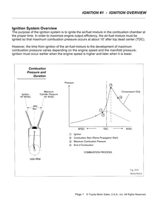
  • 1. IGNITION #1 - IGNITION OVERVIEW Ignition System Overview The purpose of the ignition system is to ignite the air/fuel mixture in the combustion chamber at the proper time. In order to maximize engine output efficiency, the air-fuel mixture must be ignited so that maximum combustion pressure occurs at about 10' after top dead center (TDC). However, the time from ignition of the air-fuel mixture to the development of maximum combustion pressure varies depending on the engine speed and the manifold pressure; ignition must occur earlier when the engine speed is higher and later when it is lower. Page 1 © Toyota Motor Sales, U.S.A., Inc. All Rights Reserved.
  • 2. IGNITION #1 - IGNITION OVERVIEW In early systems, the timing is advanced and retarded by a governor advancer in the distributor. Furthermore, ignition must also be advanced when the manifold pressure is low (i.e. when there is a strong vacuum). However, optimal ignition timing is also affected by a number of other factors besides engine speed and intake air volume, such as the shape of the combustion chamber, the temperature inside the combustion chamber, etc. For these reasons, electronic control provides the ideal ignition timing for the engine. Page 2 © Toyota Motor Sales, U.S.A., Inc. All Rights Reserved.
  • 3. IGNITION #1 - IGNITION OVERVIEW Electronic Spark Advance Overview In the Electronic Spark Advance (ESA) system, the engine is provided with nearly ideal ignition timing characteristics. The ECM determines ignition timing based sensor inputs and on its internal memory, which contains the optimal ignition timing data for each engine running condition. After determining the ignition timing, the ECM sends the ignition Timing signal (IGT) to the igniter. When the IGT signal goes off, the Igniter will turn on shut off primary current flow in the ignition coil producing a high voltage spark (7kV - 35kV) in the cylinder. Since the ESA always ensures optimal ignition timing, emissions are lowered and both fuel efficiency and engine power output are maintained at optimal levels. Types of Ignition Systems Ignition systems are divided into three basic categories: • Distributor. • Distributorless Ignition System (DLI) Electronic Ignition. • Direct Ignition System (DIS). Page 3 © Toyota Motor Sales, U.S.A., Inc. All Rights Reserved.
  • 4. IGNITION #1 - IGNITION OVERVIEW Essential Ignition System Components Regardless of type the essential components are: • Crankshaft sensor (Ne signal). • Camshaft sensor (also called Variable Valve Timing sensor) (G signal). • Igniter. • Ignition coil(s), harness, spark plugs. • ECM and inputs. Ignition Spark Generation The ignition coil must generate enough power to produce the spark needed to ignite the air/fuel mixture. To produce this power, a strong magnetic field is needed. This magnetic field is created by the current flowing in the primary coil. The primary coil has a very low resistance (approximately 1-4 ohms) allowing current flow. The more current, the stronger the magnetic field. The power transistor in the igniter handles the high current needed by the primary coil. Another requirement to produce high voltages is that the current flow in the primary coil must be turned off quickly. When the transistor in the igniter turns off, current flow momentarily stops and the magnetic field collapses. As the rapidly collapsing magnetic field passes through the secondary winding, voltage (electrical pressure) is created. If sufficient voltage is created to overcome the resistance in the secondary circuit, there will be current flow and a spark generated. Page 4 © Toyota Motor Sales, U.S.A., Inc. All Rights Reserved.
  • 5. IGNITION #1 - IGNITION OVERVIEW NOTE: The higher the resistance in the secondary circuit, the more voltage that will be needed to get the current to flow and the shorter spark duration. This is important when observing the ignition spark pattern. IGT Signal The primary coil current flow is controlled by the ECM through the Ignition Timing (IGT) signal. The IGT signal is a voltage signal that turns on/off the main transistor in the igniter. When IGT signal voltage drops to 0 volts, the transistor in the igniter turns off. When the current in the primary coil is turned off, the rapidly collapsing magnetic field induces a high voltage in the secondary coil. If the voltage is high enough to overcome the resistance in the secondary circuit, there will be a spark at the spark plug. IGC On some ignition systems, the circuit that carries the primary coil current is called IGC. lGC is turned on and off by the igniter based on the IGT signal. Page 5 © Toyota Motor Sales, U.S.A., Inc. All Rights Reserved.
  • 6. IGNITION #1 - IGNITION OVERVIEW Igniter The primary function of the igniter is to turn on and off the primary coil current based on the IGT signal received from the ECM. The igniter or ECM may perform the following functions: • Ignition Confirmation (IGF) signal generation unit. • Dwell angle control. • Lock prevention circuit. • Over voltage prevention circuit. • Current limiting control. • Tachometer signal. It is critical that the proper igniter is used when replacing an igniter. The igniters are matched to the type of ignition coil and ECM. IGF Signal The IGF signal is used by the ECM to determine if the ignition system is working. Based on IGF, the ECM will keep power supplied to the fuel pump and injectors on most ignition systems. Without IGF, the vehicle will start momentarily, then stall. However, with some Direct Ignition Systems with the igniter in the coil, the engine will run. Page 6 © Toyota Motor Sales, U.S.A., Inc. All Rights Reserved.
  • 7. IGNITION #1 - IGNITION OVERVIEW IGF Signal Detection using CEMF There are two basic methods of detecting IGF. Early systems used the Counter Electromotive Force (CEMF) created in the primary coil and circuit for generating the IGF signal. The collapsing magnetic field produces a CEMF in the primary coil. When CEMF is detected by the igniter, the igniter sends a signal to the ECM. This method is no longer used. IGF Detection Using Primary Current Method The primary current level method measures the current level in the primary circuit. The minimum and maximum current levels are used to turn the IGF signal on and off. The levels will vary with different ignition systems. Regardless of method, the Repair Manual shows the scope Page 7 © Toyota Motor Sales, U.S.A., Inc. All Rights Reserved.
  • 8. IGNITION #1 - IGNITION OVERVIEW pattern or provides you with the necessary voltage reading to confirm that the igniter is producing the IGF signal. Lack of an IGF on many ignition systems will produce a DTC. On some ignition systems, the ECM is able to identify which coil did not produce an IGF signal and this can be accomplished by two methods. The first method uses an IGF line for each coil. With the second method, the IGF signal is carried back to the ECM on a common line with the other coil(s). The ECM is able to distinguish which coil is not operating based on when the IGF signal is received. Since the ECM knows when each cylinder needs to be ignited, it knows from which coil to expect the IGF signal. Page 8 © Toyota Motor Sales, U.S.A., Inc. All Rights Reserved.
  • 9. IGNITION #1 - IGNITION OVERVIEW Dwell Angle Control This circuit controls the length of time the power transistor (current flow through the primary circuit) is turned on. The length of time during which current flows through the primary coil generally decreases as the engine speed rises, so the induced voltage in the secondary coil decreases. Dwell angle control refers to electronic control of the length of time during which primary current flows through the ignition coil (that is, the dwell angle) in accordance with distributor shaft rotational speed. Lock Prevention Circuit At low speeds, the dwell angle is reduced to prevent excessive primary current flow, and increased as the rotational speed increases to prevent the primary current from decreasing. This circuit forces the power transistor to turn off if it locks up (if current flows continuously for a period longer than specified), to protect the ignition coil and the power transistor. Over Voltage Prevention Circuit This circuit shuts off the power transistor(s) if the power supply voltage becomes too high, to protect the ignition coil and the power transistor. Page 9 © Toyota Motor Sales, U.S.A., Inc. All Rights Reserved.
  • 10. IGNITION #1 - IGNITION OVERVIEW Current Limiting (Over Current Prevention) Current limiting control is a system that improves the rise of the flow of current in the primary coil, ensuring that a constant primary current is flowing at all times, from the low speed to the high speed range, and thus making it possible to obtain a high secondary voltage. The coil's primary resistance is reduced improving the current rise performance, and this will increase the current flow. But without the current limiting circuit, the coil or the power transistor will burn out. For this reason, after the primary current has reached a fixed value, it is controlled electronically by the igniter so that a larger current will not flow. Since the current-limiting control limits the maximum primary current, no external resistor is needed for the ignition coil. NOTE: Since igniters are manufactured to match ignition coil characteristics, the function and construction of each type are different. For this reason, if any igniter and coil other than those specified are combined, the igniter or coil may be damaged. Therefore, always use the correct parts specified for the vehicle. Tachometer Signal On some systems the Tach signal is generated in the igniter. Page 10 © Toyota Motor Sales, U.S.A., Inc. All Rights Reserved.
  • 11. IGNITION #1 - IGNITION OVERVIEW NE Signal and G Signal Though there are different types of ignition systems, the use of the NE and G signals is consistent. The NE signal indicates crankshaft position and engine RPM. The G signal (also called VVT signal) provides cylinder identification. By comparing the G signal to the NE signal, the ECM is able to identify the cylinder on compression. This is necessary to calculate crankshaft angle (initial ignition timing angle), identify which coil to trigger on Direct Ignition System (independent ignition), and which injector to energize on sequential fuel injection systems. As ignition systems and engines evolved, there have been modifications to the NE and G signal. Timing rotors have different numbers of teeth. For some G signal sensors, a notch is used instead of a tooth to generate a signal. Regardless, you can determine what style is used by visually examining the timing rotor or consulting the Repair Manual. Many of the different styles are represented with their respective ignition system. Page 11 © Toyota Motor Sales, U.S.A., Inc. All Rights Reserved.
  • 12. IGNITION #1 - IGNITION OVERVIEW ASSIGNMENT NAME: ___________________________ 1. What is Electronic Spark Advance? 2. List the three types of ignition systems: 3. List the five essential ignition system components: 4. Explain the detail the function of the igniter: 5. Explain in detail the function and purpose of both the IGT, IGF, and IGC signals: 6. Define the term Dwell Angle Control”: 7. Explain in detail the function and purpose of both the NE and G signals: Page 12 © Toyota Motor Sales, U.S.A., Inc. All Rights Reserved.