

Empfohlen
Weitere ähnliche Inhalte
Was ist angesagt?
Was ist angesagt? (20)
Andere mochten auch
Andere mochten auch (12)
Ähnlich wie Retaining wall/level backfill
Ähnlich wie Retaining wall/level backfill (20)
Mehr von Timóteo Rocha
Mehr von Timóteo Rocha (10)
Kürzlich hochgeladen
Kürzlich hochgeladen (20)
Retaining wall/level backfill
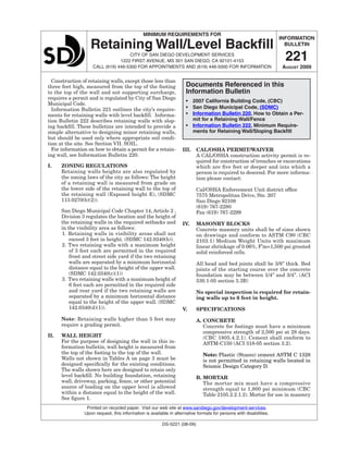
- 1. INFORMATION BULLETIN 221 August 2009 MINIMUM REQUIREMENTS FOR Retaining Wall/Level Backfill CITY OF SAN DIEGO Development Services 1222 FIRST AVENUE, MS 301 SAN DIEGO, CA 92101-4153 Call (619) 446-5300 for appointments and (619) 446-5000 for information Printed on recycled paper. Visit our web site at www.sandiego.gov/development-services. Upon request, this information is available in alternative formats for persons with disabilities. DS-5221 (08-09) Construction of retaining walls, except those less than three feet high, measured from the top of the footing to the top of the wall and not supporting surcharge, requires a permit and is regulated by City of San Diego Municipal Code. Information Bulletin 221 outlines the city’s require- ments for retaining walls with level backfill. Informa- tion Bulletin 222 describes retaining walls with slop- ing backfill. These bulletins are intended to provide a simple alternative to designing minor retaining walls, but should be used only where appropriate soil condi- tion at the site. See Section VII. SOIL. For information on how to obtain a permit for a retain- ing wall, see Information Bulletin 220. I. Zoning regulations Retaining walls heights are also regulated by the zoning laws of the city as follows: The height of a retaining wall is measured from grade on the lower side of the retaining wall to the top of the retaining wall (Exposed height E), (SDMC 113.0270(b)(2)). San Diego Municipal Code Chapter 14, Article 2 , Division 3 regulates the location and the height of the retaining walls in the required setbacks and in the visibility area as follows: 1. Retaining walls in visibility areas shall not exceed 3 feet in height. (SDMC 142.0340(b)). 2. Two retaining walls with a maximum height of 3 feet each are permitted in the required front and street side yard if the two retaining walls are separated by a minimum horizontal distance equal to the height of the upper wall. (SDMC 142.0340(c)(1)) 3. Two retaining walls with a maximum height of 6 feet each are permitted in the required side and rear yard if the two retaining walls are separated by a minimum horizontal distance equal to the height of the upper wall. (SDMC 142.0340(d)(1)). Note: Retaining walls higher than 5 feet may require a grading permit. II. WALL HEIGHT For the purpose of designing the wall in this in- formation bulletin, wall height is measured from the top of the footing to the top of the wall. Walls not shown in Tables A on page 3 must be designed specifically for the existing conditions. The walls shown here are designed to retain only level backfill. No building foundation, retaining wall, driveway, parking, fence, or other potential source of loading on the upper level is allowed within a distance equal to the height of the wall. See figure 1. IiI. Cal/osha permit/waiver A CAL/OSHA construction activity permit is re- quired for construction of trenches or excavations which are five feet or deeper and into which a person is required to descend. For more informa- tion please contact: Cal/OSHA Enforcement Unit district office 7575 Metropolitan Drive, Ste. 207 San Diego 92108 (619) 767-2280 Fax (619) 767-2299 IV. MASONRY BLOCKS Concrete masonry units shall be of sizes shown on drawings and conform to ASTM C90 (CBC 2103.1) Medium Weight Units with maximum linear shrinkage of 0.06%, F’m=1,500 psi grouted solid reinforced cells. All head and bed joints shall be 3/8” thick. Bed joints of the starting course over the concrete foundation may be between 1/4” and 3/4”. (ACI 530.1-05 section 3.3B) No special inspection is required for retain- ing walls up to 6 feet in height. V. SPECIFICATIONS A. CONCRETE Concrete for footings must have a minimum compressive strength of 2,500 psi at 28 days. (CBC 1805.4.2.1). Cement shall conform to ASTM-C150 (ACI 318-05 section 3.2). Note: Plastic (Stucco) cement ASTM C 1328 is not permitted in retaining walls located in Seismic Design Category D. B. MORTAR The mortar mix must have a compressive strength equal to 1,800 psi minimum (CBC Table 2105.2.2.1.2). Mortar for use in masonry Documents Referenced in this Information Bulletin • 2007 California Building Code, (CBC) • San Diego Municipal Code, (SDMC) • Information Bulletin 220, How to Obtain a Per- mit for a Retaining Wall/Fence • Information Bulletin 222, Minimum Require- ments for Retaining Wall/Sloping Backfill
- 2. Page of 6 City of San Diego • Information Bulletin 221 August 2009 construction shall conform to ASTM C 270 and shall conform to the proportion specifications of Table 2103.8(1) or the property specifica- tions of Table 2103.8(2) of the CBC. C. GROUT Grout must have a compressive strength equal to 2,000 psi minimum. Grout shall conform to Table 2103.12 or to ASTM C 476. When grout conforms to ASTM C 476, the grout shall be specified by proportion requirements or prop- erty requirements (CBC 2103.12) E. REINFORCING STEEL Reinforcing steel must be deformed and com- ply with ASTM A 615 (CBC 2103.13.1), Grade 60. When one continuous bar cannot be used, a lap or splice of 40-bar diameters is required. All bars shall be clean of loose flaky rust, grease or other materials likely to impair bond. (ACI 318-05 section 5.7) Reinforcement in concrete shall be protected from corrosion and exposure to chlorides. (ACI 318-05 Section 7.7.6). Concrete protection for reinforcement shall be at least 3” to earth when the concrete is poured against the earth. (ACI 318-05 Section 7.7.1). One #4 reinforcing bar must be placed longitu- dinally within the wall in a bond beam block every 16 inches as the blocks are laid up. See Figure 2. F. mortar key To insure proper bonding between the footing and the first course of block, a mortar key must be formed by embedding a flat 2x4 flush with and at the top of the freshly placed footing. It should be removed after the concrete has started to harden (about 1 hour). A mortar key may be omitted if the first course of block is set into the fresh concrete and a good bond is obtained. Vi. Wall drains Wall drains must be placed at 6-foot intervals along the length of the wall and located just above the level of the soil or paving on the front face of the wall. The drains may be formed by placing a block on its side at 6-foot intervals, by leaving out the mortar in the vertical spaces between all the blocks in the first course above the soil or paving (head joint) on the front face of the wall, by installing 4-inch diameter drain line behind the wall, or by any other acceptable equivalent method. Backfill behind wall drains or open head joints must be loose rubble or gravel at least 12 inches wide and extending from the top of the wall to the top of the footing. VII. SOIL DESIGN CRITERIA This information bulletin is to be used only when the soils to be retained are not expansive (i.e. sandy soils). The design of this information bul- letin is based on the following criteria: 1. Soil type: granular, non-cohesive soil backfill. 2. Active earth pressure with an equivalent fluid weight of 30 pounds per cubic foot. 3. Passive earth pressure with an equivalent fluid weight of 150 pounds per cubic. 4. Allowable bearing value of 1,500 psf. 5. Soil friction factor 0.25. If existing soil conditions do not meet these design criteria or the conditions are unknown, walls should be designed by a State of California licensed civil engineer or architect. A soil report may be required. Note: Soil lateral pressure due to earthquake motion is not included. viIi. INSPECTIONS Inspections must be performed during several phases of construction. Please call for inspections at the following times: A. A footing inspection is needed when the excavation for a footing has been dug with the steel tied securely in its final position, and the site is ready for the concrete to be placed. B. A masonry pregrout inspection is required when the block has been laid and the steel is in place, but before the grout has been placed. 1. If cleanout holes are used, block may be laid to the full height at the grout pour before calling for the pregrout inspec- tion. Grout shall be placed in a continu- ous pour in grout lifts not exceeding 6 feet. 2. If cleanout holes are not used, a masonry pregrout inspection is required prior to each grout pour. Block cannot be laid higher than the grout pour. Note that cleanouts are required for all grout pours over 5 feet in height. C. After grouting is completed and rock or rub- ble wall drains are in place, but before earth backfill is placed, call for a backfill/drainage inspection. D. When all work has been completed, call for a final inspection.
- 3. August 2009 City of San Diego • Information Bulletin 221 Page of 6 Table A / Requirements for Various Wall Heights 1,2,3,4,5 Wall Type I II III Wall Height (H)6 3’ - 4” 4’ -0” 4’ - 8” 5’ - 4” 6’ - 0” Exposed Wall Height (E)7 2’ - 4” 3’ - 0” 3’ - 8” 4’ - 4” 5’ - 0” Stem Block Thickness 6” 8” 8” 8” 8” / 12” Heel Dimension (L) 1’ - 3” 1’ - 7” 1’ - 4” 1’ - 4” 1’ - 9” Toe Dimension (T) 6” 6” 11” 1’ - 6” 1’ - 4” Vert Bars (A) Vert Bars (B) #4 @ 24” #4 @ 24” #4 @ 24” #4 @ 24” #4 @ 24” #4 @ 24” #4 @ 16” #4 @ 16” #4 @ 16” #4 @ 16” Footing Width (W) 1’ - 9” 2’ - 1” 2’ - 3” 2’ - 10” 3’ - 1” Footing Bars (C) none none none #4 @ 24” #4 @ 24” Key Distance from Toe none none 6” 12” 12” Key (W x D) none none 6” x 8” 8” x 9” 8” x 12” FOOTNOTES: 1 Tables A makes the following assumptions: f’y= 600000psi Fs= 24000 Solid grouting Using half f’m stress 2 Walls not shown in Table A must be designed specifically for the actual conditions. 3 All construction must comply with the specifications shown in this information bulletin. 4 When Wall Type III is required, the first 32 inches of block must be 12-inch wide masonry units. I=6” Block II=8” Block III=12” Block 5 Footing depth shall be 24 inches below finish grade and 12 inches of compacted soil is required on top of foot- ing to stabilize the wall. 6 For the purpose of the structural design, wall height shall be measured from the top of the footing to the top of the wall. 7 For zoning requirements fence height shall be measured from finish grade.
- 4. Page of 6 City of San Diego • Information Bulletin 221 August 2009 Figure 2 / Typical Control Joints Figure 1 / Surcharge and Slope Setbacks
- 5. August 2009 City of San Diego • Information Bulletin 221 Page of 6 Figure 3 / Typical I or II Retaining Wall with Level Backfill
- 6. Page of 6 City of San Diego • Information Bulletin 221 August 2009 Figure 4 / Type III Retaining Wall with Level Backfill