Variable Area Flowmeter Basics: Fundamentals and Descriptions
•
0 gefällt mir•1,629 views

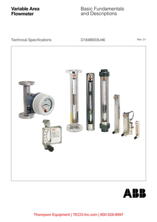
The Variable Area Flowmeter is an instrument for measuring the flow of liquids and gases in pipelines. It includes a vertical tube through which the fluid flows whose diameter increases from the bottom to the top and a float which can move vertically in the tube. As the flow increases this float moves to a higher position until its resistance to the fluid flow is balanced by the float’s buoyed weight in the fluid, a value which is constant and independent of the flowrate. The position of the float is a measure of the flowrate. The flowrate values can be read on a scale.

Empfohlen
Empfohlen
Weitere ähnliche Inhalte
Was ist angesagt?
Was ist angesagt? (19)
Ähnlich wie Variable Area Flowmeter Basics: Fundamentals and Descriptions
Ähnlich wie Variable Area Flowmeter Basics: Fundamentals and Descriptions (20)
Mehr von Thompson Equipment Company
Mehr von Thompson Equipment Company (10)
Kürzlich hochgeladen
Kürzlich hochgeladen (20)
Variable Area Flowmeter Basics: Fundamentals and Descriptions
- 1. D184B003U46 Rev. 01Technical Specifications Variable Area Flowmeter Basic Fundamentals and Descriptions Thompson Equipment | TECO-Inc.com | 800-528-8997
- 2. Thompson Equipment | TECO-Inc.com | 800-528-8997
- 3. 3 1 Principle of Operation................................................................................................. 5 2 Basic Design................................................................................................................ 5 3 Determination of the Meter-Float Combination........................................................ 6 4 Viscosity Influence (1/2’’ to 2’’).................................................................................. 6 5 Definition of Operating Pressure for Variable Area Flowmeters ............................ 9 5.1 Locations for a Needle Valve......................................................................................................... 9 6 Floats.......................................................................................................................... 10 6.1 Ball floats..................................................................................................................................... 10 6.2 Floats with tail guides .................................................................................................................. 10 6.3 Low pressure drop floats ............................................................................................................. 10 6.4 Pole guided floats........................................................................................................................ 10 6.5 Floats Type „BL“. . ...................................................................................................................... 10 6.6 Tapered floats.............................................................................................................................. 10 6.7 Floats with guide rods.................................................................................................................. 10 7 Meter Tubes ............................................................................................................... 11 7.1 Glass Meter Tubes ...................................................................................................................... 11 7.1.1 Tri-flat meter tubes sizes 1/16’’ to 1/4’’ ........................................................................................ 11 7.1.2 Plain tapered meter tubes sizes 1/2’’ to 1/4’’............................................................................... 11 7.1.3 Plain tapered meter tubes sizes 1/2’’ to 2’’ .................................................................................. 11 7.1.4 Beadguide meter tubes sizes 1/2’’ to 2’’...................................................................................... 11 7.2 Metal Meter Tubes....................................................................................................................... 11 7.2.1 Plain tapered meter tubes ........................................................................................................... 11 8 Scales......................................................................................................................... 12 9 Glass Meter Tube Designations............................................................................... 13 10 Float Designations .................................................................................................... 13 11 Ball Float Designations............................................................................................. 13 12 Accuracy Classes...................................................................................................... 14 13 Allowable Operating Pressures for Glass Meter Tubes when Metering Gases.......................................................................................................... 14 13.1 Laboratory Flowmeter Series 10A1017/18 .................................................................................. 14 13.2 Glass Meter Tube Flowmeter Series 10A1187, 10A1190 ........................................................... 15 13.3 Glass Tube Flowmeter Series 10A2700...................................................................................... 15 13.4 Purgemeter Series 10A3239S..................................................................................................... 15 13.5 „Purgemaster“ Series 10A6100 ................................................................................................... 16 13.6 Glass Meter Tube Flowmeter for Bypass Metering Series 10B1197........................................... 16 14 Material Selections for Variable Area Flowmeters. . . . . . . . . . . . . . . . . . . . . . . . . 17 Contents Thompson Equipment | TECO-Inc.com | 800-528-8997
- 4. Thompson Equipment | TECO-Inc.com | 800-528-8997
- 5. 5 Variable Area Flowmeter Basic Fundamentals and Descriptions D184B003U46 1 Principle of Operation The principles of operation of the Variable Area Flowmeters are described in the VDI/VDE-Guideline 3513 as follows: The Variable Area Flowmeter is an instrument for measuring the flow of liquids and gases in pipelines. It includes a vertical tube through which the fluid flows whose diameter increases from the bottom to the top and a float which can move vertically in the tube. As the flow increases this float moves to a higher position until its resistance to the fluid flow is balanced by the float’s buoyed weight in the fluid, a value which is constant and independent of the flowrate. The position of the float is a measure of the flowrate. The flowrate values can be read on a scale. 2 Basic Design In its simplest construction, a Variable Area Flowmeter consists of the measurement elements (see Fig. 2-1). Float (1), meter tube (2), flowrate scale (3), fittings (5), flanged or threaded, for mounting in the pipeline and O-Rings (7) to provide the seals. The float movement is restricted by the float stops (4) and a protective housing (6) surrounds the meter tube. The flowrate scale for flowmeters with glass meter tubes is preferably applied directly on the meter tube. Variable Area Flowmeters generally have a 1: 12.5 measurement range which corresponds to 8 to 100 %. If the mechanical, thermal or chemical resistance properties of the glass meter tube are not adequate for certain applications, metal meter tubes can be utilized. The float position, which is a measure of the instantaneous flowrate, is indicated external to the metal meter tube by a transmission system (see Fig. 2-2). Converters can be incorporated to convert the flowrate values to a current output signal (0/4...20 mA) for flow control, remote flow indication or recording applications. Alarm values can also be indicated and signaled. The Specification Sheets for the individual Variable Area Flowmeter designs include the flow range tables in addition to the design features, specifications, material availability and dimension information. The flow range tables list the maximum flowrate for the individual meter tube sizes and for the meter tube - float combinations which are available. Fig. 2-1: Basic Construction, Glass Tube Flowmeter 5 7 4 1 3 2 4 7 5 1 Float 2 Meter Tube 3 Scale 4 Float Stop, Inlet/Outlet 5 Inlet/Outlet Fittings 6 Housing 7 O-Rings 6 Thompson Equipment | TECO-Inc.com | 800-528-8997
- 6. 6 Variable Area Flowmeter Basic Fundamentals and Descriptions D184B003U46 Fig. 2-2: Basic Construction, Armored Metal Tube Flowmeter The flowrates listed flow range tables are based on floats made of 304 [1.4301] stainless steel (density ρf = 8.02 g/cm3 ) and for liquids, on water (density ρ = 1 g/cm3 , viscosity η = 1 mPas) while for gases the ranges listed are based on air at normal conditions (tn = 0 °C; pn = 1.013 bar). 3 Determination of the Meter-Float Combination The precision manufacture of the meter tubes and the floats permits use of the simplified calculations based on Guideline VDI/VDE 3513 Calculation of Volume or Mass Flowrate. An ABB software program Flow Select is available for selecting an appropriate flowmeter type for a specific application. The program FlowCalc can be used to select the optimal instrument using the actual operating conditions which exist in the application. Both of these programs are available upon request. 4 Viscosity Influence (1/2’’ to 2’’) The geometric design of the floats assures operation independent of over wide ranges of viscosity. That is, within these ranges the viscosity of the fluid can vary without affecting the flowrate measurements. The Viscosity Immunity Ceiling is listed in the column VIC in the flow range tables for these Variable Area Flowmeters. If the VIC value calculated for the application is less than or exactly equal to the VIC value listed in the flow range tables, there is no viscosity effect on the measurements. η = Dynamic viscosity of the fluid [mPas] ρf = Density of the float used for the table (ρ = 7,92 g/cm3 ) ρf1 = Density of the float actually used ρ1 = Density of the fluid If a VIC number higher than the value listed in the Table 4-1 is calculated, the scale for the flowmeter must be must be created for specific fluid viscosity at the factory. Meter Tube Scale Float Magnet Follower System Float Magnet VIC η (ρf 1) 1⋅– (ρf1 ρ1) ρ1⋅– ----------------------------------⋅= Thompson Equipment | TECO-Inc.com | 800-528-8997
- 7. 7 Variable Area Flowmeter Basic Fundamentals and Descriptions D184B003U46 Table 4-1 provides a means to correct the values listed for gases whose operating conditions deviate from the normal conditions (same operating conditions) used during the calibration. Example: A specific flowmeter, which was calibrated for air, normal density 1.293 kg/m3 is to be used for Nitrogen, normal density 1.25 kg/m3 . Read the factor 1.02 (heavy border) from the intersection of the Air column and the Nitrogen row. The flowrate values indicated by this flowmeter are to be multiplied by this factor. Note: New normal density larger: Factor < 1 New normal density smaller: Factor > 1 If the operating temperature and/or the operating pressure changes, the multiplication factors for the correction should be changed using the following equations: Normal or weight units Actual volume units Kp = Correction Factor for pressure Kt = Correction Factor for temperature p1 = 1.013 bar + calibration pressure in bar p2 = 1.013 bar + new operating pressure in bar t1 = 273 K + calibration temperature in °C t2 = 273 K + new calibration temperature in °C Calculation of the Correction Factors for Liquid Density Changes Volume Flowrate Mass Flowrate KF = Correction Factor ρf1 = Density of the float being used ρ1 = Density of the calibration liquid ρ2 = Density of the new liquid Kp p2 p1 -----= Kp p1 p2 -----= Kt t1 t2 ----= Kt t2 t1 ----= KF (ρf1 ρ2) ρ1⋅– (ρf1 ρ1) ρ2⋅– ----------------------------------= KF (ρf1 ρ2) ρ2⋅– (ρf1 ρ1) ρ1⋅– ----------------------------------= Thompson Equipment | TECO-Inc.com | 800-528-8997
- 8. 8 Variable Area Flowmeter Basic Fundamentals and Descriptions D184B003U46 4.1. Normal Density Correction Table for Volume Units (Meter Tube Sizes 1/2’’ to 2’’) Table 4-1: Normal Density Correction Table Gas existing new NormalDensitykg/m3for0°C and1013mbar Acetylene Ammonia Ammoniadiss. Argon Butane Chlorine NaturalGas Helium CarbonDioxide CarbonMonoxide Krypton Air Methane Neon Propane Propylene Oxygen SulfurDioxide NitricOxide NitrousOxide Nitrogen Hydrogen Acetylene 1.17 1 0.81 0.566 1.23 1.51 1.66 0.84 0.39 1.3 1.04 1.79 1.05 0.78 0.88 1.32 1.28 1.11 1.58 1.07 1.3 1.04 0.28 Ammonia 0.77 1.232 1 0.697 1.52 1.86 2.04 1.04 0.48 1.6 1.27 2.2 1.3 0.96 1.08 1.62 1.58 1.36 1.95 1.32 1.6 1.27 0.34 Ammonia diss. 0.374 1.77 1.43 1 2.18 2.67 2.93 1.5 0.69 2.3 1.83 3.16 1.86 1.38 1.55 2.32 2.26 1.96 2.8 1.89 2.3 1.83 0.49 Argon 1.78 0.81 0.66 0.458 1 1.22 1.34 0.68 0.32 1.05 0.84 1.45 0.85 0.63 0.71 1.06 1.04 0.9 1.28 0.87 1.05 0.84 0.22 Butane 2.67 0.66 0.54 0.374 0.816 1 1.1 0.56 0.26 0.86 0.66 1.18 0.57 0.52 0.58 0.87 0.85 0.73 1.05 0.71 0.86 0.68 0.18 Chlorine 3.214 0.603 0.49 0.341 0.74 0.91 1 0.51 0.235 0.78 0.62 1.08 0.63 0.47 0.53 0.79 0.77 0.67 0.95 0.65 0.78 0.62 0.17 Natural Gas 0.83 1.19 0.963 0.67 1.46 1.79 1.97 1 0.46 1.54 1.23 2.12 1.25 0.93 1.04 1.56 1.52 1.31 1.88 1.27 1.54 1.23 0.33 Helium 0.178 2.56 2.08 1.45 3.16 3.87 4.25 2.16 1 3.34 2.65 4.6 2.7 2.0 2.24 3.37 3.28 2.83 4.06 2.74 3.34 2.65 0.71 Carbon Dioxide 1.98 0.77 0.624 0.435 0.948 1.16 1.27 0.65 0.3 1 0.79 1.37 0.8 0.6 0.67 1.01 0.98 0.85 1.22 0.82 1.0 0.79 0.21 Carbon Monox- ide 1.25 0.967 0.785 0.547 1.19 1.46 1.6 0.82 0.38 1.26 1 1.73 1.02 0.76 0.85 1.27 1.24 1.07 1.53 1.04 1.26 1.0 0.27 Krypton 3.74 0.56 0.454 0.316 0.69 0.845 0.927 0.47 0.22 0.73 0.58 1 0.6 0.44 0.49 0.73 0.72 0.62 0.89 0.6 0.73 0.58 0.15 Air 1.293 0.95 0.77 0.54 1.17 1.44 1.58 0.8 0.37 1.24 0.98 1.7 1 0.75 0.83 1.25 1.22 1.05 1.5 1.02 1.24 0.98 0.26 Methane 0.717 1.28 1.04 0.72 1.58 1.93 2.12 1.08 0.5 1.66 1.32 2.3 1.34 1 1.12 1.68 1.63 1.41 2.02 1.37 1.66 1.32 0.35 Neon 0.9 1.14 0.925 0.645 1.41 1.72 1.89 0.96 0.44 1.48 1.18 2.04 1.2 0.8 1 1.5 1.46 1.26 1.8 1.22 1.48 1.18 0.31 Propane 2.019 0.761 0.618 0.43 0.94 1.15 1.26 0.64 0.295 0.99 0.79 1.36 0.8 0.6 0.66 1 0.97 0.84 1.2 0.81 0.99 0.79 0.20 Propylene 1.915 0.78 0.634 0.44 0.96 1.18 1.296 0.66 0.305 1.02 0.81 1.4 0.82 0.61 0.69 1.03 1 0.86 1.24 0.84 1.02 0.81 0.22 Oxygen 1.43 0.905 0.734 0.51 1.12 1.37 1.5 0.76 0.35 1.18 0.93 1.62 0.95 0.71 0.79 1.19 1.16 1 1.43 0.97 01.18 0.93 0.21 Sulfur Dioxide 2.93 0.632 0.513 0.36 0.78 0.95 1.05 0.53 0.245 0.82 0.65 1.13 0.66 0.5 0.55 0.83 0.81 0.7 1 0.68 0.82 0.65 0.25 Nitric Oxide 1.34 0.93 0.76 0.53 1.15 1.41 1.55 0.79 0.36 1.22 0.96 1.67 0.98 0.73 0.82 1.23 1.2 1.03 1.48 1 1.22 0.96 0.174 Nitrous Oxide 1.98 0.77 0.624 0.435 0.948 1.16 1.27 0.65 0.3 1.0 0.79 1.37 0.8 0.6 0.67 1.01 0.98 0.85 1.22 0.82 1 0.79 0.25 Nitrogen 1.25 0.967 0.785 0.547 1.19 1.46 1.6 0.82 0.38 1.26 1.0 1.73 1.02 0.76 0.85 1.27 1.24 1.07 1.53 1.04 1.26 1 0.27 Hydrogen 0.089 3.36 2.94 2.05 4.47 5.48 6.01 3.05 1.41 4.72 3.75 6.5 3.81 2.84 3.18 4.76 4.64 4.01 5.74 3.88 4.72 3.75 1 Thompson Equipment | TECO-Inc.com | 800-528-8997
- 9. 9 Variable Area Flowmeter Basic Fundamentals and Descriptions D184B003U46 5 Definition of Operating Pressure for Variable Area Flowmeters The term „Operating Pressure“ is defined as the pressure which exists in the meter tube of the flowmeter. This pressure is usually identical to the pressure immediately downstream of the flowmeter. The pressure drop through the flowmeter can be ignored. 5.1 Locations for a Needle Valve The locations for a needle valve, at the inlet or the outlet, is immaterial when metering liquids. Due to the compressible nature of gases, it is generally recommended that the needle valve be located at the outlet of the flowmeter when metering gases. This assures that the pressure in the meter tube remains constant and is independent of back pressure variations. If the back pressure remains constant then the needle valve can be installed in the flowmeter inlet. For measurements at atmospheric pressure, the needle valve must be installed in the inlet of the flowmeter. Additionally, for gas measurements, the actual location for the needle valve (in-/outlet side) must always be considered when determining the operating pressure. As a result of the density changes of the compressed gas due to pressure changes, the upward forces acting on the float and thereby the indication of the flowrate values also change. In order to assure that the operating pressure in the region of the meter tube always remains constant, a control valve should be installed as follows (see Fig. 5-1). Fig. 5-1: Location of the Needle Valve Example: A Flowmeter without needle valve; P2 = operating pressure B Flowmeter with needle valve in inlet; P2 = operating pressure C Flowmeter with needle valve in outlet; P1 = operating pressure D Flowmeter with needle valve in inlet and outlet; P2 = operating pressure A B C D Thompson Equipment | TECO-Inc.com | 800-528-8997
- 10. 10 Variable Area Flowmeter Basic Fundamentals and Descriptions D184B003U46 6 Floats 6.1 Ball floats are used for metering smaller flowrates in sizes 1/16’’ to 3/8’. In order to provide maximum versatility in changing flow ranges in a single meter tube size, ball floats made of a variety of materials with differing densities are available. 6.2 Floats with tail guides used in combination with beadguide meter tubes and percent scales represent the standard Variable Area Flowmeter design. The float type „GSVT“ is largely independent of viscosity effects and is available in a variety of materials and weights. Flowrates approximately 25% to 30% higher can be measured by reversing the float head „GNSVT“. This float geometry is not suitable for fluids with higher viscosities. The VIC values listed in the flow range tables must be observed. The float is guided by the metering edge and the tail guide at the three ribs in the beadguide meter tube. 6.3 Low pressure drop floats were developed especially for metering gases at low pressures and assure an extremely low pressure drop through the flowmeter. They are used in combination with the beadguide metering tubes. 6.4 Pole guided floats in conjunction with plain tapered meter tubes have a hole drilled through their length axis and are guided by a pole rigidly positioned in the meter tube. 6.5 Floats Type „BL“. . . are especially suitable for high flowrates in the smaller sizes. They are guided by the three ribs in the beadguide meter tubes. 6.6 Tapered floats are used only in cylindrical tubes with an orifice. The guide rods, a part of the float, move in guide elements attached to the tube to center and guide the float. A magnet in the float transmits the float position to an externally mounted indicator. 6.7 Floats with guide rods in tapered metal meter tubes operate similar to the float position transmission and guide system described above. They are essentially viscosity insensitive and are available with the float head geometries previously described (see Chap. 6.2). The wide variety of different meter tube - float - scale combinations which are available provide approximately 100,000 possible Variable Area Flowmeter designs available for quoting. Fig. 6-1: Float Shapes A = Reading Edge Ball Float Float with Float for Low Float with BL Tail Guide Pressure Drop Pole Guide Float Thompson Equipment | TECO-Inc.com | 800-528-8997
- 11. 11 Variable Area Flowmeter Basic Fundamentals and Descriptions D184B003U46 7 Meter Tubes 7.1 Glass Meter Tubes 7.1.1 Tri-flat meter tubes sizes 1/16’’ to 1/4’’ are used in the smallest sizes. The tubes expand conically in the flow direction and contain three flats which are parallel to the central axis of the meter tube. The ball float is guided by these three flats over the entire flow range and the minimal space between the float and flats in the meter tube assures readability of the float position even in cloudy fluids. The float is guided exactly in the middle of the meter tube. 7.1.2 Plain tapered meter tubes sizes 1/2’’ to 1/4’’ are also used with ball floats (see Chap. 6.1) for metering smaller flowrates. Their accuracy is not as high as the tri-flat meter tubes and are therefore only utilized for simple applications. The ball floats are cen- tered in the plain tapered meter tubes by the flowing fluid. 7.1.3 Plain tapered meter tubes sizes 1/2’’ to 2’’ are usually only used for extreme operating conditions (pressure shocks, vibrating pipelines, etc.). In the size 2’’, higher flow range end values are possible because flow area is greater than in the beadguide meter tubes. The float is guided by a pole guide in the plain tapered meter tubes (see Chap. 6.4). 7.1.4 Beadguide meter tubes sizes 1/2’’ to 2’’ are the standard in this size range. This meter tube type incorporates three ribs which are parallel to the center axis of the meter tube and perform the same functions as the flats described in Chap. 7.1.1 for the tri-flat meter tubes. They guide the float over the entire flow range. Here also the minimal space between the float reading edge and the beadguides assures readability of the float position even in cloudy fluids. The are used together with the float shapes described in Chap. 6.2 and Chap. 6.3. Fig. 7-1: Meter Tube Designs 7.2 Metal Meter Tubes 7.2.1 Plain tapered meter tubes with guide elements rigidly attached to the meter tubes in combination with the floats described in Chap. 6.7 are the standard elements of our all metal, armored flowmeter program. The float position is transmitted to the indicator by a magnet follower system. Tri-flat Meter Tube Beadguide Meter Tube Plain Tapered Meter Tube Thompson Equipment | TECO-Inc.com | 800-528-8997
- 12. 12 Variable Area Flowmeter Basic Fundamentals and Descriptions D184B003U46 8 Scales Diameter Ratio Scale Dt/Df The diameter ratio scale is a linear representation of the ratio between the effective internal meter tube diameter (Dt) and the float diameter (Df). It can be used universally for both liquids and gases and is particularly advantageous when operating conditions vary. A flowrate table is included at no cost for converting the scale indications into flowrate values. Conversions to other operating conditions can be readily made using our Calculation Program FlowCalc. This scale type is the standard for the tri-flat meter tubes with a ball floats. Percent Scale The linearized percent scale is the standard scale for all other Variable Area Flowmeters, predominantly the beadguide and plain tapered meter tubes (see Chap. 7.1.3). It indicates a percentage value based on maximum flowrate and extends over a range from 8 to 100%. Knowledge of the operating conditions, the physical characteristics of the fluid and the geometric design of the float can be used to readily calculate or convert the maximum flowrate value. Each percent scales provides the guaranteed accuracy. Direct Reading Scale This scale indicates the volume or mass flowrate per unit of time directly (e.g. l/h Hydrogen, cm3 /min H2O). It is valid only for exactly defined operating conditions. The universal applicability of the meter tubes is somewhat limited by the use of direct reading scales. Millimeter Scale This scale is usually only used when a fixed flowrate is to be reproduced and the actual flowrate value plays a subordinate role. For applications with viscous fluids this scale may be considered as universal. Thompson Equipment | TECO-Inc.com | 800-528-8997
- 13. 13 Variable Area Flowmeter Basic Fundamentals and Descriptions D184B003U46 9 Glass Meter Tube Designations 10 Float Designations 11 Ball Float Designations FP - 1/2 - 27 - G - 19/80 Mfg’r: ABB Meter tube size (inch) Taper (max. Dt/Df) Meter tube with beadguides G Meter tube with plain taper P Scale length (inch) Meter Tube Drawing No. 10A1017 36 10A1018 35 10A1187, 10A1190, 10B1190 80 1/2” to 2” 10A1187, 10A1190, 10A6132/42 1/16” to 1/4” 81 10A6134/44 19 10A6131/41 37 10A3239 »S« 1/16” to 1/4” 197 1/2” - GSVT - 45 Float size Beadguide design Float head shape Tail guide Float drawing No. NSV NSV Type - Material Density (g/cm3 ) Glass (black) 2.28 (only 1/4”, 3/8”) CD Glass (black) 2.53 (only 1/16”, 1/8”) BG Sapphire (red) 3.98 SA Stainless steel 304 [1.4301] 8.02 SS Carboloy 14.95 CA Tantalum 16.6 TA Size 1/16” 16 1/8” 18 1/4” 14 3/8” 38 Thompson Equipment | TECO-Inc.com | 800-528-8997
- 14. 14 Variable Area Flowmeter Basic Fundamentals and Descriptions D184B003U46 12 Accuracy Classes The accuracy specifications for the Variable Area Flowmeters are defined by the various Accuracy Classes in the VDE/VDI Guideline 3513, Pg. 2, in which an error range is assigned for each Accuracy Class. The maximum allowable error is the sum of the following partial errors. 1st. Partial error: 3/4 of the value assigned for the Accuracy Class is the error in percent of rate 2nd. Partial error: 1/4 of the value assigned for the Accuracy Class is the error in percent of full scale The total error can be calculated for a specific flowrate in % of rate as follows: M = Measured value in flowrate units E = Scale end value in flowrate units K = Value for the Accuracy Class per VDI/VDE 3513/2 E = Total error in % of rate. 13 Allowable Operating Pressures for Glass Meter Tubes when Metering Gases The assurance of the safety of personnel and the environment is an important quality hallmark of the ABB measurement instruments. ABB meets the challenges of the new safety regulations. To protect from dangerous splinters should a meter tube accidentally burst, our glass meter tube flowmeters for metering gases incorporate a protective component (protection cap or protection tube). The protective component also provides protection from direct external mechanical effects. 13.1 Laboratory Flowmeter Series 10A1017/18 Comments – Listed max. allow. operating pressure for 20 °C fluid temperature and 20 °C ambient temperature – Max. fluid temperature: 0...95 °C – Is shipped without protective component Flowrate in % Accuracy Class 1 1.6 2.5 4 6 Total Error in % of Rate 100 90 80 70 60 50 40 30 20 10 1.000 1.028 1.063 1.107 1.167 1.250 1.375 1.583 2.000 3.250 1.600 1.644 1.700 1.771 1.807 2.000 2.200 2.533 3.200 5.200 2.500 2.569 2.656 2.768 2.917 3.125 3.438 3.958 5.000 8.125 4.000 4.111 4.250 4.429 4.667 5.000 5.500 6.333 8.000 13.000 6.000 6.167 6.375 6.643 7.000 7.500 8.250 9.500 12.000 19.500 E (3/4M 1/4E) K/M⋅+= Model Max. Allowable Operating Pressure (bar) 10A1017 10A1018 0.5 0.5 Thompson Equipment | TECO-Inc.com | 800-528-8997
- 15. 15 Variable Area Flowmeter Basic Fundamentals and Descriptions D184B003U46 13.2 Glass Meter Tube Flowmeter Series 10A1187, 10A1190 Comments – Listed max. allow. operating pressure for 20 °C fluid temperature and 20 °C ambient temperature – Max. ambient temperature: 40 °C – Max. fluid temperature: 0...100 °C – For fluid or ambient temperatures above 30 °C the max. allow. operating pressure is reduced by 1.05 %/1 °C (see Fig. 13-1) 13.3 Glass Tube Flowmeter Series 10A2700 Comments – Listed max. allow. operating pressure for 20 °C fluid temperature and 20 °C ambient temperature – Max. fluid temperature: 0...150 °C 1) Meter tube sizes 1/2’’ and 3/4’’ max. 5 bar with PC-Protective Tube 13.4 Purgemeter Series 10A3239S Comments – Listed max. allow. operating pressure for 20 °C fluid temperature and 20 °C ambient temperature – Max. ambient temperature: 40 °C – Max. fluid temperature: 0...80 °C – For fluid or ambient temperatures above 30 °C the max. allow. operating pressure is reduced by 1.05 %/1 °C (see Fig. 13-1) Flowmeter Size Meter Tube Size Max. allow. Operating Pressure (bar) Standard Design Alarm Design 1/4’’ 1/2’’ 3/4’’ 1’’ 11/2’’ 2’’ 11/16’’...1/4’’ 1/2’’ 3/4’’ 1’’ 11/2’’ 2’’ 30 17 13 10 4 2 – 17 13 10 4 2 Flowmeter Size Meter Tube Size Max. allow. Operating Pressure (bar) 1/4’’ 3/4’’1) 11/2’’ 1/16’’...1/4’’ 1/2’’...1’’ 11/2’’...2’’ 6,0 0,5 1,0 Flowmeter Size Meter Tube Size Max. allow. Operating Pressure (bar) 1/4’’ 1/16’’ 1/8’’ 1/4’’ 18 18 18 Thompson Equipment | TECO-Inc.com | 800-528-8997
- 16. 16 Variable Area Flowmeter Basic Fundamentals and Descriptions D184B003U46 13.5 „Purgemaster“ Series 10A6100 Comments – Listed max. allow. operating pressure for 20 °C fluid temperature and 20 °C ambient temperature – Max. ambient temperature: 40 °C – Max. fluid temperature: 0...100 °C – For fluid or ambient temperatures above 30 °C the max. allow. operating pressure is reduced by 1.05 %/1 °C (see Fig. 13-1) 13.6 Glass Meter Tube Flowmeter for Bypass Metering Series 10B1197 Comments – Listed max. allow. operating pressure for 20 °C fluid temperature and 20 °C ambient temperature – Max. ambient temperature: 40 °C – Max. fluid temperature: 0...100 °C – For fluid or ambient temperatures above 30 °C the max. allow. operating pressure is reduced by 1.05 %/1 °C (see Fig. 13-1) Fig. 13-1: Allowable Operating Pressure as a Function of the Temperature Warning The flowmeters should only be operated with protective cap or protective tube installed in front of the glass meter tube. It is essential that the maximum allowable operating conditions be observed (see Instruction Bulletin for Installation and Start-up). Note: The allowable operating pressure values are static pressure values. Selection and installation recommendations for Variable Area Flowmeters are to be observed. Proper handling and operation of the flowmeter (see Instruction Bulletin) and observing the specified allowable operating conditions are the exclusive responsibility of the user. Flowmeter Size Scale Length Max. allow. Operating Pressure (bar) 1/4’’ 38/70 100/130 250 18 18 18 Flowmeter Size Max. allow. Operating Pressure (bar) 1/2’’ 17 100 100 50 5030 0 t [°C] P [%]zul. Applicable for Models 10A1187 10A1190 10A3239S 10A6100 10B1197 ! Thompson Equipment | TECO-Inc.com | 800-528-8997
- 17. 17 Variable Area Flowmeter Basic Fundamentals and Descriptions D184B003U46 14 Material Selections for Variable Area Flowmeters This selection does not claim to be complete, however it does offer ease when selecting materials. At the present time these recommendations are based on laboratory tests by the material manufacturers or upon repetitve applications in practice. When in doubt the material recommendations should be obtained from the manufacturer since he has the most expreience. Not included are the ball floats sizes 1/16” to 1/4”. If a glass meter tube is sutiable for the application, then the assumption that a ball float made of glass or sapphire should also be suitable can be made. Fittings Floats O-Rings Meter Tube Meter Tube for All Metal Flow- meters Fluid Concentrationin% Temperaturein°C 304[1.4301]/Brass Bronze 1,4301/Steel 316Ti[1.4571] PVC/40°C HastelloyC PVDF/PTFE 316Ti[1.4571] PVC/40°C 1,4301 HastelloyC HastelloyB Titanium PVDF/PTFE Buna-N Viton-A EthylenePropylene Glass 316Ti[1.4571] HastelloyC PTFEmax.125°C Acetaldehyde × × × × × Acetone × × × × × × × Acetylene × × × × × × × Acrolein × × a.A. × × Ethane × × × × × × × Äthancarbonsäure × × × × × Äthanolamin × × × × × × × Ether, Methyl, Ethyl × × × × × × × Ethyl Acetate × × × × × × × Ethyl Acrylate × × × × × × × Ethyl Ether × × × × × × × Ethyl Alcohol × × × × × × × Ethyl Cellulose × × × × × × × Ethylene × × × × × × × Ethylene Chlorohyrin × × × × × × × Ethylen Chloride × × × × × × × Ethylene Diamine × × × × × × Ethylene Dichloride × × × × × Ethylene Glycol × × × × × × × Ethylene Oxide × × × × × × × Caustic potash, see Calcium Hydroxide Caustic Soda, see Sodiun Hydroxide Alaun, see Kalialaun Alcohol × × × × × × × Aluminium Sulfate × × × × × × × Formic Acid 0-100 80 × × × × × Ammonia gas × × × × × × × × × Ammonia solution 1 25 × × × × × × × × × Ammonia liquid × × × × × Ammonium Chloride × × × × × Ammonium Hydroxide × × × × × × × Ammonium Carbonate × × × × × × × Thompson Equipment | TECO-Inc.com | 800-528-8997
- 18. 18 Variable Area Flowmeter Basic Fundamentals and Descriptions D184B003U46 Fittings Floats O-Rings Mess- rohr Meter Tube for All Metal Flowmeters Fluid Concentrationin% Temperaturein°C 304[1.4301]/Brass Bronze 1,4301/Steel 316Ti[1.4571] PVC/40°C HastelloyC PVDF/PTFE 316Ti[1.4571] PVC/40°C 1,4301 HastelloyC HastelloyB Titanium PVDF/PTFE Buna-N Viton-A EthylenePropylene Glass 316Ti[1.4571] HastelloyC PTFEmax.125°C Ammonium Nitrate x x x x x Ammonium Phosphate x x x x x Ammonium Sulfate x x x x x Amyl Acetate x x x x x Amyl Alcohol x x x x x x x x Amyl Chloride x x x x x x x Aniline x x x x x x x Antichlor, see Sodium Thiosulfate Mahic acid x x x x x Argon x x x x x x x x Asphalt x x ATE-Brake Fluid x x x x x x Barium Chloride x x x x x Barium Hydroxide x x x x x x x Barium Nitrate x x x x x Barium Sulfide x x x x x Benzaldehyde x x x x x x Benzine x x x x x x x Benzoic Acid x x x x x Benzol x x x x x x x Acrid salt, see Mangnesium Sulfate Prissic Acid x x x x x Blood x x x x x Borax x x x x x x Boron Chloride x x x x x x Boric Acid x x x x x Bromine gas x x x x x Bromwasserstoffsäure x x x x x Bunker C Oil x x Butadiene x x x x x x x Butane x x x x x x x Butane, lliquid x x x x x x x Butyric acid x x x x x Butyl Acetate x x x x x x x Botyl Alcohol x x x x x x Butylene x x x x x x Thompson Equipment | TECO-Inc.com | 800-528-8997
- 19. 19 Variable Area Flowmeter Basic Fundamentals and Descriptions D184B003U46 Fittings Floats O-Rings Meter Tube Meter Tube for Ganzmetall- Durchflussm. Fluid Concentrationin% Temperaturein°C 304[1.4301]/Brass Bronze 1,4301/Steel 316Ti[1.4571] PVC/40°C HastelloyC PVDF/PTFE 316Ti[1.4571] PVC/40°C 1,4301 HastelloyC HastelloyB Titanium PVDF/PTFE Buna-N Viton-A EthylenePropylene Glass 316Ti[1.4571] HastelloyC PTFEmax.125°C Calcium Bisulfite x x x x x x x Calcium Chloride 40 x x x x x x x x Calcium Chloride >40 x x x x x x Calcium Hydroxide x x x x x x x Calcium Hypochloride x x x x x x Carbonic Acid x x x x x Chlorine (dry gas) x x x x x Clorine (liquid) x x x x x x x x Chlorine (wet gas) x x x x x x x Chlorine Dioxide (dry gas) x x x x x x x x Chlorine line 3 30 x x x x x x Chloroform x x x x x x x x Chlorine Water 20 x x x x x x x x Hydrochloric Gas (HCL-Gas) x x x x x x x x x Chromic Acid 50 40 x x x x → @ 20 % x x x x Chromic Acid, pure, SO3-free 10-50 x x x x x Condopal x x x x x x Condorid-S x x x x x x x Cyclohexane x x x x x x x Cyclohexanol x x x x x x x Cyclohexanole x x x x x x x Cyclopropane x x x x x x x x Steam x x Diacetone x x x x x x x x Diacetone Alcohol x x x x x x x x Diethylene Glycol x x x x x x x Diboran x x x x x Dibutylphtalate x x x x x Dichlormethane x x x x x Diese Oil, light x x x x x x Diisopropylekton x x x x x Dimethylether, see Ether, Methyl Diphenyl x x x x x x Jet Fuel JP 1 & 4 x x x x x x x x Ferric-II-Chloride x x x x x x x x Ferric-III-Chloride x x x x x x x x Thompson Equipment | TECO-Inc.com | 800-528-8997
- 20. 20 Variable Area Flowmeter Basic Fundamentals and Descriptions D184B003U46 Dye Fittings Floats O-Rings Mess- rohr Meter Tube for Ganzmetall- Durchflussm. Fluid Concentrationin% Temperaturein°C 304[1.4301]/Brass Bronze 1,4301/Steel 316Ti[1.4571] PVC/40°C HastelloyC PVDF/PTFE 316Ti[1.4571] PVC/40°C 1,4301 HastelloyC HastelloyB Titanium PVDF/PTFE Buna-N Viton-A EthylenePropylene Glass 316Ti[1.4571] HastelloyC PTFEmax.125°C Ferric-III-Chloride (high conc.& temp.) x x x x Ferric-II-Sulfate x x x x x Ferric-III-Sulfate x x x x x Electrolyte Solution 40 x x x x x x x Electrolyte Solution >40 100 x x x x x Natural Gas x x x x x x x x Crude Oil x x Vinegar x x x x x Acetic Acid 98.5 99.9 25 x x x x x Acetic Acid 60 20 x x x x x Acetic Anhydride x x x x x Dye, color not transparent x x Dye, color transparent x x x x x x x Fatty Acid Flour x x x Hydrochloric Acid, all concentrations max. 25 x x Formaldehyde (Formalin) x x x x x Photographic solutions x x x x x x x Frigen (note type) x x x x x m x x Gelantin x x x x x Sodium Sulphate Glucose x x x x x x x Glysantin x x x x x x x x Glycerine x x x x x x x Mine Water, acidic x x x x x Urea 20 x x x x x x x Urea 135 x x x x x Heating Oil x x x x x x x x Helium x x x x x x x x Heptane x x x x x x x Hexane x x x x x x x Wood Alcohol, see Methyl Alcohol Hydraulic Oil x x x x x x x x Isobutylacetate x x x x x x x x Isobutylene x x x x x Isocyanate x x x x x Thompson Equipment | TECO-Inc.com | 800-528-8997
- 21. 21 Variable Area Flowmeter Basic Fundamentals and Descriptions D184B003U46 Fittings Floats O-Rings Meter Tube Meter Tube for Ganzmetall- Durchflussmesser Fluid Concentrationin% Temperaturein°C 304[1.4301]/Brass Bronze 1,4301/Steel 316Ti[1.4571] PVC/40°C HastelloyC PVDF/PTFE 316Ti[1.4571] PVC/40°C 1,4301 HastelloyC HastelloyB Titanium PVDF/PTFE Buna-N Viton-A EthylenePropylene Glass 316Ti[1.4571] HastelloyC PTFEmax.125°C Iodine solution 10 65 x x x x x Kalialaun 105 20 x x x x x Potassium Chlorate x x x x x x x Potassium Chloride x x x x x x x x Potassium Cyanide x x x x x x x Potassium Hydroxide = Potassium iodide 20-50 x x Kaliumjodid x x x x x x x Potassium Permanganate x x x x x x x Potassium Phosphate x x x x x Potassium Sulfate x x x x x x x Carbolic Acid (Phenol) x x x x x x Kerosene x x x x x x x x Boiler water x x Salt, see Sodium Chloride Salt solutions x x x x x x x x x Carbon Dioxide x x x x x x x x Carbon Monoxide x x x x x x x x Carbonic Acid x x x x x x x Carbon Bisulfide x x x x x x x Creosote x x x x x x x Krypton x x x x x x x x Copper Chloride 20 x x x x x x x x Copper Sulfate x x x x x Laughing gas (Nitrous Oxide) x x x x x x x x Latex x x Linseed Oil x x x x x x x Illuminaing gas x x x x x x x Lithium Chloride x x x x x x x Air x x x x x x x x x Mangnesium Chloride x x x x x x x x Mangnesium Hydroxide x x x x x x x Mangnesium Nitrate x x x x x x x Mangnesium Sulfate = Acrid salt x x x x x x x Mahic acid x x x x x Mahic acid <40 >40 x x x x x x x x x x Manganese Sulfate x x x x x Thompson Equipment | TECO-Inc.com | 800-528-8997
- 22. 22 Variable Area Flowmeter Basic Fundamentals and Descriptions D184B003U46 Fittings Floats O-Rings Meter Tube Meter Tube for All Metal Flowmeters Fluid Concentrationin% Temperaturein°C 304[1.4301]/Brass Bronze 1,4301/Steel 316Ti[1.4571] PVC/40°C HastelloyC PVDF/PTFE 316Ti[1.4571] PVC/40°C 1,4301 HastelloyC HastelloyB Titanium PVDF/PTFE Buna-N Viton-A EthylenePropylene Glass 316Ti[1.4571] HastelloyC PTFEmax.125°C Machine Oil - not transparent x x Machine Oil - transparent x x x x x x x x Molasses solution x x x x x x x Mercaptan x x x x x x x Methane x x x x x x x x Methanol, see Methyl Alcohol Methyl Ethyl Ketone x x x x x MethylAlcohol, Methanol x x x x x x x x Methylbenzol seeToluene Methylene Chloride (gas) x x x x x x x Methylene Chloride (liquid) x x x x x Methylisobutylketon x x x x x Methylmethacrylate x x x x x Milk x x Lactid acid x x x x x Miscella (Acetone + soj bean oil) x x x x x Naphtha x x x x x x x Naphtalin x x x x x x x Sodium Aluminate x x x x x x x Sodium Acetate x x x x x Sodium Bicarbonate x x x x x Sodium Bisulfate x x x x x Sodium Bisulfite x x x x x Sodium Chloride (salt) x x x x x x x x Sodium Chlorite x x x x x x x Sodium Cyanide x x x x x x x Sodium Dichromate x x x x x x Sodium di/triphosphate x x x x x x x Natridithionit, see Hydrosulfit Sodium Glutamate x x x x x x x Sodium Hypochlorite x x x x x x x x Sodium Carbonate (Soda) x x x x x x x Sodium Nitrate (saltpeter) x x x x x x x Sodium Perborate x x x x x Sodium Peroxide x x x x x Sodium Phosphate x x x x x Thompson Equipment | TECO-Inc.com | 800-528-8997
- 23. 23 Variable Area Flowmeter Basic Fundamentals and Descriptions D184B003U46 Fittings Floats O-Rings Meter Tube Meter Tube for All Metal Flowmeters Fluid Concentrationin% Temperaturein°C 304[1.4301]/Brass Bronze 1,4301/Steel 316Ti[1.4571] PVC/40°C HastelloyC PVDF/PTFE 316Ti[1.4571] PVC/40°C 1,4301 HastelloyC HastelloyB Titanium PVDF/PTFE Buna-N Viton-A EthylenePropylene Glass 316Ti[1.4571] HastelloyC PTFEmax.125°C Sodium or Trisodium Phosphate x x x x x x x Sodium Silicate (water glass) x x x x x x x Sodium Sulfate x x x x x x x Sodium Sulfide x x x x x x x Sodium Sulfite x x x x x x x Sodiumthiosulfat x x x x x Sodium Hydoxide 0-20 20 x x x x x x x Caustic Soda > 20 20 x x x x x x x Caustic Soda > 20 > 20 x x Neon x x x x x x x x Nickel Chloride x x x x x x x Nickel Sulfate x x x x x Nitrobenzol x x x x x x Sulphurate Oil x x x x x Ölsäure x x x Oleum, see Sulfuric Acid x x Olive Oil x x x x x x x Oxalic Acid, cold x x x x x Ozone x x x x x x x x Palmin acid x x x x x x x Paraffine x x x x x x x x Pectin x x x x x Pentan x x x x x x x Perchlorethylene x x x x x x x x Petroleum x x x x x x x x Vegatable Oil x x x x x x x x Phenol, see Carbolic Acid x x x x x Phenylamine x x x x x Phosgene x x Phosphinic acid x x x x x Phosphorous, liquid x x Phosphoric Acid x x x x x x x Pikin acid x x x x x Propane (gas) x x x x x x x x Propane, liquid x x x x x x x Propylene x x x x x x x x Thompson Equipment | TECO-Inc.com | 800-528-8997
- 24. 24 Variable Area Flowmeter Basic Fundamentals and Descriptions D184B003U46 Fittings Floats O-Rings Meter Tube Meter Tube for Ganzmetall- Durchflussm. Fluid Concentrationin% Temperaturein°C 304[1.4301]/Brass Bronze 1,4301/Steel 316Ti[1.4571] PVC/40°C HastelloyC PVDF/PTFE 316Ti[1.4571] PVC/40°C 1,4301 HastelloyC HastelloyB Titanium PVDF/PTFE Buna-N Viton-A EthylenePropylene Glass 316Ti[1.4571] HastelloyC PTFEmax.125°C Propylene Oxide x x x x x Pyrid x x x x x x x Salicic Acid x x x x x x Nitric Acid < 50 x x x x x x x x x x Nitric Acid, concentrated. x x x x x Nitric Acid, fuming 20 AL/95.5% x AL/95.5% x x x x Hydrochloric Acid x x x x x x x Brine 50-65 x x x x x x Oxygen x x x x x x x x Sea Water x x x x x x x x Silicone Oil x x x x x Skydrol 500 B & C/7000 x x x x x x x x Soda, see Sodium Carbonate Soy Oil x x x x x x Spaltglas x x x x x x x Spinning Bath Solution x x x x x Sulfitbase x x x x Sulfur, molten x Sulfur Chloride, dry x x x x x Sulfur Dioxide, dry x x x x x x x x x Sulfur Dioxide, wet x x x x x x x Sulfur Dioxide, liquid x x x x x x x Sulfur Hexafluoride gas x x x x x x x x x Sulfurous Acid 20-30 x x x x x x x x x x Sulfuric Acid ≤ 90 x x x x x x x x Sulfuric Acid 90-95 x x x x x x x x x Sulfuric Acid 96 20 x x x x x x x x Sulfuric Acid 98 conc. 20 x x x x x x x x x x x x x Hydrogen Sulfide, dry x x x x x x x x Hydrogen Sulfide, wet x x x x x Starch x x x x x x Stearic Acid x x x x x x Nitrogen x x x x x x x x x Nitrogen Dioxide x x x x x Nitrogen Monoxide x x x x x x x Stickstoffoxydul, see Laughing Gas Thompson Equipment | TECO-Inc.com | 800-528-8997
- 25. 25 Variable Area Flowmeter Basic Fundamentals and Descriptions D184B003U46 * with double O-Ring seal Materials are to be specified by the user, because in some cases 316Ti/316 [1.4571/1.4401] are unsatisfactory, alternate 1.4439 ❍ per Type Fittings Floats O-Rings Meter Tube Meter Tube for All Metal Flowmeters Fluid Concentrationin% Temperaturein°C 304[1.4301]/Brass Bronze 1,4301/Steel 316Ti[1.4571] PVC/40°C HastelloyC PVDF/PTFE 316Ti[1.4571] PVC/40°C 1,4301 HastelloyC HastelloyB Titanium PVDF/PTFE Buna-N Viton-A EthylenePropylene Glass 316Ti[1.4571] HastelloyC PTFEmax.125°C Styrene x x x x x Tannin x x x x x Tar x x Turpentine x x x x x x x Tetrachlorine x x x x x x x TID x x x x x Toluene (methyl benzene) x x x x x x x Träthanolarmin x x x x x x x Trichlorethane x x x x x x x Trichlorethylene x x x x x x x Trisodium Phosphate x x x x x x x Turbineöl x x x x x x x x Vinyl Acetate x x x x x x x Vinyl Chloride x x x x x x x Water x x x x x x x x Water, demineralized x x x x x x x Water, distilled x x x x x Water, desalinated x x x x x x x Water Glass, see Sodium Silicate Hydrogen x x x x x x x x Hydrogen Peroxide x x x x x Wine x x x x x Tartar acid x x x x x Seasoning x x x x x Cellulose Acetate x x x x x Zinc Chloride x x x x x x x Zinc Sulfate x x x x x Citric Acid x x x x x Sugar Liquor x x x x x x Xenon x x x x x x x x Xylene, Xylol x x x x x x x Thompson Equipment | TECO-Inc.com | 800-528-8997
- 26. ABB Automation Products GmbH Dransfelder Straße 2 D-37079 Goettingen, Germany Tel. +49(0)5 51 - 90 50 Fax +49(0)5 51 - 90 57 77 http://www.abb.de/durchfluss Rights reserved to make technical revisions Printed in the Fed. Rep. of Germany D184B003U46 Rev. 01 Issued 06/01 Thompson Equipment | TECO-Inc.com | 800-528-8997