
Empfohlen
Empfohlen
Weitere ähnliche Inhalte
Was ist angesagt?
Was ist angesagt? (16)
Ähnlich wie SAMPLE REVIT DRAWINGS-SUNIT K DHINGRA-COMPLETE - URS
Ähnlich wie SAMPLE REVIT DRAWINGS-SUNIT K DHINGRA-COMPLETE - URS (20)
SAMPLE REVIT DRAWINGS-SUNIT K DHINGRA-COMPLETE - URS
- 2. BLOCK D BLOCK F BLOCK H BLOCK E BLOCK B BLOCK C BLOCK A HOTEL TERMINAL BLOCK G ENDERBY HSE KEY PLAN NORTH STAIRS 2-2 URS-D-XX-SX-05-0001 D2 D4 D1 D3 DP DL DJ DNDK DMDHDC DDDBDA DE DF DG 3940 4400 5550 568368443202 6250 5250 5900 3650 6700 5550 1775 3300 4160 1215 C1 C1 C1 C3 C1C3 C3 C3C3 C3 C3 C1 C3 C3 C1 C3 C3 C3 C3 9-9 URS-D-B2-SX-02-0002 10-10 URS-D-B2-SX-02-0002 MJ MJ SSL +5.330 m SSL +5.720 m 350DP RC PODIUM SLAB 740DP RC TRANSFER SLAB PHASE 1A BOUNDARY 10-10 URS-D-B2-SX-02-0003 TOU +5.635 m 1350x740DPRCBEAM 890x740DP RC BEAM SSL +5.530 m 550DP RC TRANSFER SLAB BLOCK C BEYOND PHASE 1A MJ MJ 1-1 URS-D-B2-SX-02-0003 12-12 URS-D-B2-SX-02-0004 21-21 URS-D-B2-SX-02-0004 22-22 URS-D-B2-SX-02-0004 PROVISION FOR 2500 x 2500 HOLE FOR TOWER CRANE. EXACT SIZE AND LOCATION TBC BY BEL. FLP LINE OF TEMPORARY SUPPORT TO SLAB EDGE SSL +5.720 m 350DP RC TRANSFER SLAB 900x740DP RC BEAM AREA UNDER DESIGN DEVELOPMENT AWAITING INFORMATION FROM LANDSCAPE ARCH. RE: PLANTERS & RETAINING WALL LEVELS 300 THK. RETAINING WALL @ PHASE 2 CONSTRUCTION SEQUENCE AND PROGRAMME TO BE DISCUSSED WITH CONTRACTOR UPON RECEIPT OF FULL SET OF LANDSCAPING INFORMATION. TBC BY BEL MJ SLAB EDGE T.B.C BY ARCHITECT SLAB EDGE T.B.C BY ARCHITECT 192 1691 425 1921102 425 800 2116 1955 1294 400 330 680 200 444 102 444 1927 3067 400 200 370 609 400 98 1926 400 220 1522 1522 110 400 1522 110 1483 440 582 1000 893 4242254524 787 4207 557 361 1543 1625 842 23.17° 66.83° 49.12° 1641 2029 434 204041 893 1 URS-D-XX-PL-02-0009 5008 5993 2 URS-D-XX-SX-02-0003 1900 1083 2769 5965 1 URS-D-XX-SX-02-0003 2645 145 2645 PHASE 1A BOUNDARY 5 - 5 URS-D-XX-SX-02-0003 2881 2513 2 - 2 URS-D-XX-PL-03-0003 1 URS-D-XX-PL-03-0003 N 961286.258 E 1063445.364 N 992172.775 E 1076633.479 N 969301.206 E 1080273.689 THERMAL JOINTS 369 500 1228 601 SSL +5.330 m 350DP RC PODIUM SLAB SSL +5.330 m 350DP RC PODIUM SLAB 300thk RC RETAINING WALL BELOW 6 URS-D-XX-SX-02-0003 1666 4 - 4 URS-D-XX-SX-02-0003 155 1571 155 1785 1076 110 523 110 110 1830 402 196 402 402 225 BLOCK W ORK W ALL 225BLOCKWORKW ALL N 1010016.124 E 1076633.479 N 998573.242 E 1076633.479 N 998573.242 E 1086150.959 N 1007203.614 E 1090675.282 8 - 8 URS-D-XX-SX-02-0003 1291 2696 1666 3424 1696 309 1171 499 3386 499 2797 499 3371 287 2012 176 971 1605 302 1605 2797 1605 3371 366 1606 1593 540 270 270 270 270 STEPINSOFFIT STEPINSOFFIT 1. THIS DRAWING IS TO BE READ IN CONJUNCTION WITH THE RELEVANT SPECIFICATIONS AND ALL OTHER RELEVANT DRAWINGS ISSUED BY THE ENGINEER AND ARCHITECT. 2. ALL DIMENSIONS AND LEVELS TO BE CHECKED ON SITE AND THE ENGINEER NOTIFIED OF ANY DISCREPENCIES PRIOR TO COMMENCEMENT OF WORK. 3. DO NOT SCALE FROM THIS DRAWING. 4. ALL LEVELS AND DIMENSIONS ARE IN MILLIMETRES UNLESS NOTED OTHERWISE. 5. FOR CONCRETE GRADES REFER TO SPECIFICATIONS. 6. CONTRACTOR TO CONFIRM ALL LEVELS AND DIMENSIONS ON SITE. ANY DIMENSIONAL VARIATION PROPOSED AS A RESULT OF IRREGULARITIES IN LINE AND LEVEL ENCOUNTERED ON SITE ARE ONLY TO BE MADE AFTER AGREEMENT WITH THE CONSTRUCTION MANAGER. LEGEND DENOTES OPENING IN SLAB FOR FUTURE LIFT TO BE INFILLED WITH 'TATA STEEL' D80 ROOF DECKING FLP SHOECK THERMAL BREAK DENOTED THUS DENOTES FAIR FACED CONCRETE FINISH TO SOFFIT OF BALCONY / EXTERNAL WALKWAY. KEY DENOTES COLUMNS TO BE CHAMFERED AND FAIR FACED - DETAILS TBC BY ARCHITECT DENOTES CAST-IN DRAINAGE * DENOTES CAST-IN GULLYG Revision Details By Check Date Suffix Purpose of issue Client Project Title Drawing Title Drawn Checked Approved Date URS Internal Project No. Suitability. Scale @ A1 Zone / Mileage This document has been prepared in accordance with the scope of URS' appointment with its client and is subject to the terms of that appointment. URS accepts no liability for any use of this document other than by its client and only for the purposes for which it was prepared and provided. Only written dimensions shall be used. © URS Infrastructure & Environment UK Limited URS Infrastructure & Environment UK Limited www.ursglobal.com Drawing Number. Rev St George's House, 5 St George's Road Wimbledon, London SW19 4DR Tel +44 (0)20 8944 3300 Fax +44 (0)20 8944 3301 Designed 1 : 100 12/01/201606:33:31 ENDERBY WHARF LLP UPPER GROUND FLOOR GENERAL ARRANGEMENT SHEET 1 OF 2 SKD OS PW DEC 2013 47068268 CONSTRUCTION ENDERBY WHARF, GREENWICH BLOCK D URS-D-00-PL-04-0020 AA STRUCTURAL COLUMN SCHEDULE REF SIZE C1 220x880 RC COLUMN C2 350x880 RC COLUMN C3 200x800 RC COLUMN C5 300x800 RC COLUMN C6 300x300 RC COLUMN C7 350x350 RC COLUMN UNSUPPORTED SLAB EDGES TO BE SUPPORTED TEMPORARILY, DESIGNED BY TEMPORARY WORKS CONTRACTOR PRELIMINARY AND/OS 20/12/13 REVISED AS CLOUDED. ISSUED FOR TENDER PE/OS 14/02/14 REVISED AS CLOUDED. ISSUED FOR TENDER. PE/OS 24/02/14 NORTH STAIRS ADDED . LIFT AMENDED AND PODIUM STAIRS REVISED.BLOCK C COLUMNS ADDED. BALCONY THERMAL BREAK SHOWN JE/OS 25/04/14 DRAINAGE HOLES ADDED TO PODIUM SLAB. DIMENSION ADDED JE/OS xx/04/14 Revision Details By Check Date Suffix Purpose of issue Client Project Title In addition to the hazard/risks normally associated with the types of work detailed on this drawing take note of above. It is assumed that all works on this drawing will be carried out by a competent contractor working, where appropriate, to an appropriate method statement. SAFETY, HEALTH AND ENVIRONMENTAL INFORMATION BOX CONSTRUCTION RISKS MAINTENANCE / CLEANING RISK DEMOLITION RISKS Drawing Title Drawn Checked Approved Date URS Internal Project No. Suitability. Scale @ A1 Zone / Mileage This document has been prepared in accordance with the scope of URS' appointment with its client and is subject to the terms of that appointment. URS accepts no liability for any use of this document other than by its client and only for the purposes for which it was prepared and provided. Only written dimensions shall be used. © URS Infrastructure & Environment UK Limited URS Infrastructure & Environment UK Limited www.ursglobal.com Drawing Number. Rev NOTES St George's House, 5 St George's Road Wimbledon, London SW19 4DR Tel +44 (0)20 8944 3300 Fax +44 (0)20 8944 3301 Designed 1 : 100 12/01/201606:33:31 ENDERBY WHARF LLP UPPER GROUND FLOOR GENERAL ARRANGEMENT SHEET 1 OF 2 SKD OS PW DEC 2013 47068268 CONSTRUCTION ENDERBY WHARF, GREENWICH BLOCK D URS-D-00-PL-04-0020 AA FOR CONTINUATION SEE DRAWING URS-D-00-PL-04-0021 PRELIMINARY AND/OS 20/12/13 REVISED AS CLOUDED. ISSUED FOR TENDER PE/OS 14/02/14 REVISED AS CLOUDED. ISSUED FOR TENDER. PE/OS 24/02/14 NORTH STAIRS ADDED . LIFT AMENDED AND PODIUM STAIRS REVISED.BLOCK C COLUMNS ADDED. BALCONY THERMAL BREAK SHOWN JE/OS 25/04/14 DRAINAGE HOLES ADDED TO PODIUM SLAB. DIMENSION ADDED JE/OS xx/04/14 RC CORE WALLS TO BE 200mm THICK UNLESS NOTED OTHERWISE. STAIR CORE WAIST AND HALF LANDINGS TO BE 200mm THICK IN-SITU CONCRETE UNLESS NOTED OTHERWISE. FOR CONCRETE FINISHES REFER TO URS GENERAL NOTES DRAWING URS-X-XX-SP-02-0001 RISER VOID NOTE: TEMPORARY A393 MESH TO BE PLACED IN THE RISER VOIDS AND CAST INTO ADJACENT SLAB WITH A MINIMUM TENSION LAP OF 40xBAR DIAMETER. SS, SVP AND RWP LOCATIONS TO BE CONFIRMED BY ARCHITECTS. REFER TO HLM`s BUILDERS WORK HOLES SETTING OUT FOR FIRE COLLARS TO BE CAST IN RC SLAB. REFER TO URS DRAWING...URS-D-XX-DT-02-0005 FOR MASONARY SUPPORT AND TIE DETAILS. REFER TO URS DRAWING...URS-X-XX-SP-02-0001 FOR GENERAL NOTES. HLM TO CONFIRM SETTING OUT OF SLAB EDGES, STAIRS AND RISER OPENINGS AND UPSTAND LEVELS. T1 C2 1 T2 T2 C1 REFER TO URS DRAWING...URS-D-B2-PL-04-0009 FOR STAIRS DETAILS AND SECTION. REFER TO URS DRAWING...URS-D-XX-PL-02-0008 FOR NORTH STAIRS DETAILS AND SECTION. URS STRUCTURAL LAYOUT IS BASED ON 'HLM' DRG. No. 6415-D00-GA-128-0001 REV. C3 SLAB PENETRATIONS IS BASED ON 'HLM' DRG. No. 6415-D00-GA-128-0001 REV. C2 ! C1 C1 C1 C2
- 3. BLOCK D BLOCK F BLOCK H BLOCK E BLOCK B BLOCK C BLOCK A HOTEL TERMINAL BLOCK G ENDERBY HSE KEY PLAN 1-1 URS-D-XX-SX-05-0001 2-2 URS-D-XX-SX-05-0001 3-3 URS-D-XX-SX-05-0001 D8 D9 D7 D12 D11 D5 D4 D6 D10 DP DL DJ DNDK DMDHDC DDDBDA DE DF DG30582490270042752725248410881928 C1 C1 C1 C1 C2 C2 C1 C1 C2 C1 C2 C1 C1 C1C1C1 C1 C1 C1 250RCWALL 250RCWALL C1 C1 C1 C1 C1 C1 C1C1 C1 C1 C1 C1 C1 C1 C1 C1 C1 C1 C1 C1 C1 C1 C1 C1 C1 250 RC WALL 225DP RC SLAB 200 RC WALL 200 RC WALL 200 RC WALL SSL +5.720 m SSL +5.720 m C1 C2 7-7 URS-D-B2-SX-02-0002 C1 8-8 URS-D-B2-SX-02-0002 10-10 URS-D-B2-SX-02-0003 MJ MJ TOU +5.635 m 1350x740DP RC BEAM 4-4 URS-D-B2-SX-02-0003 12-12 URS-D-B2-SX-02-0004 19-19 URS-D-B2-SX-02-0004 20-20 URS-D-B2-SX-02-0004 220x450DP RC DOWNSTAND BEAM 220x450DPRC DOWNSTAND BEAM FLP FLP FLP FLP 225DP RC SLAB C2 C1 C1 225DP RC SLAB 225 RC WALL MJ 225 RC WALL MJ 250RCWALL 250 RC WALL SLAB EDGE T.B.C BY ARCHITECT 220 1522 1522 110 156 220 110 220 1026 1026 110 910 220 250 440 1355 440 1522 110 636 440 440 439 250 649 142 1472 110 732 110 331 187 880 993 110 960 1103 775 510 110 440 775 880 775 220 2528 800 125 880 95 470 479 559 85 350 400 110 400 400 400 400 360 3564 427 895 350 895 440 110 200 RC WALL 200RCWALL 200RCWALL 250RCWALL 200RCWALL 250RCWALL250RCWALL 1483 440 582 1000 150054 600242 1400222925751055 1180 1015 125 135 1500 12641000 985 1000 1214 990985 149 151 990985 1125 893524157791312935401552 1058 1058 1033 1087 457 2980 503 1087 932 954 3674 922 199 1857 3676 717 103454 1119 1907 3084 259 103454 1119 1715 33 749 219 180 1986 5075 136 1228 483 26 483 787 4207 557 1220 180 10 361 1543 1220 1625 842 1852 1320 3781 3779 1970 1350 415 1 - 1 URS-D-XX-SX-04-0002 3 URS-D-XX-PL-03-0001 2 URS-D-XX-PL-03-0002 4 URS-D-XX-SX-04-0001 2 URS-D-XX-SX-04-0002 1350x740DP RC BEAM 1350x740DP RC BEAM 1350x740DP RC BEAM 1125 250 1075 250 783 250 600 792 267 2058 2458 2158 242 542 1250 220x450DP RC DOWNSTAND BEAM 250X450DP RC BEAM 1228 601 1666 1678 89 150x80DP RC UPSTAND 150x80DP RC UPSTAND 275thk SUBSTATION WALL BELOW 9-9 URS-D-XX-SX-02-0003 3 URS-D-XX-SX-02-0003 150x80DP RC UPSTAND 150x80DP RC UPSTAND G 407 693 1325 155 910 268 1392 400 332 1133 1008 1479 575 1696 309 200RCWALL 125 125 911 485 618 558 420 287 2012 176 971 1605 302 1593 540 270 270 270 270 270 270 SSL +5.720 m 225DP RC SLAB SSL +5.720 m 225DP RC SLAB SSL +5.720 m 225DP RC SLAB SSL +5.720 m225DP RC SLAB SSL +5.720 m SSL +5.860 m 225DP RC SLAB SSL +5.860 m 225DP RC SLAB STEPINSOFFIT STEPINSOFFIT N 1014987.823 E 1118117.888 1. THIS DRAWING IS TO BE READ IN CONJUNCTION WITH THE RELEVANT SPECIFICATIONS AND ALL OTHER RELEVANT DRAWINGS ISSUED BY THE ENGINEER AND ARCHITECT. 2. ALL DIMENSIONS AND LEVELS TO BE CHECKED ON SITE AND THE ENGINEER NOTIFIED OF ANY DISCREPENCIES PRIOR TO COMMENCEMENT OF WORK. 3. DO NOT SCALE FROM THIS DRAWING. 4. ALL LEVELS AND DIMENSIONS ARE IN MILLIMETRES UNLESS NOTED OTHERWISE. 5. FOR CONCRETE GRADES REFER TO SPECIFICATIONS. 6. CONTRACTOR TO CONFIRM ALL LEVELS AND DIMENSIONS ON SITE. ANY DIMENSIONAL VARIATION PROPOSED AS A RESULT OF IRREGULARITIES IN LINE AND LEVEL ENCOUNTERED ON SITE ARE ONLY TO BE MADE AFTER AGREEMENT WITH THE CONSTRUCTION MANAGER. NORTH STAIRS LEGEND DENOTES OPENING IN SLAB FOR FUTURE LIFT TO BE INFILLED WITH 'TATA STEEL' D80 ROOF DECKING FLP SHOECK THERMAL BREAK DENOTED THUS DENOTES FAIR FACED CONCRETE FINISH TO SOFFIT OF BALCONY / EXTERNAL WALKWAY. KEY DENOTES COLUMNS TO BE CHAMFERED AND FAIR FACED - DETAILS TBC BY ARCHITECT DENOTES CAST-IN DRAINAGE * DENOTES CAST-IN GULLYG Revision Details By Check Date Suffix Purpose of issue Client Project Title In addition to the hazard/risks normally associated with the types of work detailed on this drawing take note of above. It is assumed that all works on this drawing will be carried out by a competent contractor working, where appropriate, to an appropriate method statement. SAFETY, HEALTH AND ENVIRONMENTAL INFORMATION BOX CONSTRUCTION RISKS MAINTENANCE / CLEANING RISK DEMOLITION RISKS Drawing Title Drawn Checked Approved Date URS Internal Project No. Suitability. Scale @ A1 Zone / Mileage This document has been prepared in accordance with the scope of URS' appointment with its client and is subject to the terms of that appointment. URS accepts no liability for any use of this document other than by its client and only for the purposes for which it was prepared and provided. Only written dimensions shall be used. © URS Infrastructure & Environment UK Limited URS Infrastructure & Environment UK Limited www.ursglobal.com Drawing Number. Rev NOTES St George's House, 5 St George's Road Wimbledon, London SW19 4DR Tel +44 (0)20 8944 3300 Fax +44 (0)20 8944 3301 Designed 1 : 100 12/01/201606:34:41 ENDERBY WHARF LLP UPPER GROUND FLOOR GENERAL ARRANGEMENT SHEET 2 OF 2 SKD OS PW FEB. 2014 47068268 CONSTRUCTION ENDERBY WHARF, GREENWICH BLOCK D URS-D-00-PL-04-0021 OS FOR CONTINUATION SEE DRAWING URS-D-00-PL-04-0020 STRUCTURAL COLUMN SCHEDULE REF SIZE C1 220x880 RC COLUMN C2 350x880 RC COLUMN C3 200x800 RC COLUMN C5 300x800 RC COLUMN C6 300x300 RC COLUMN C7 350x350 RC COLUMN REVISED AS CLOUDED. ISSUED FOR TENDER PE/OS 14/02/14 REVISED AS CLOUDED. ISSUED FOR TENDER. PE/OS 24/02/14 UPPER FLOOR TOE AMENDED TO 270mm FLP CHANGED TO SUIT JE/OS 25/04/14 SECTION MARK ADDED TO TOE DETAIL, STEP IN SOFFIT ANNOTATION ADDED TO GRID D5 JE/OS **/04/14 RC CORE WALLS TO BE 200mm THICK UNLESS NOTED OTHERWISE. STAIR CORE WAIST AND HALF LANDINGS TO BE 200mm THICK IN-SITU CONCRETE UNLESS NOTED OTHERWISE. FOR CONCRETE FINISHES REFER TO URS GENERAL NOTES DRAWING URS-X-XX-SP-02-0001 RISER VOID NOTE: TEMPORARY A393 MESH TO BE PLACED IN THE RISER VOIDS AND CAST INTO ADJACENT SLAB WITH A MINIMUM TENSION LAP OF 40xBAR DIAMETER. SS, SVP AND RWP LOCATIONS TO BE CONFIRMED BY ARCHITECTS. REFER TO HLM`s BUILDERS WORK HOLES SETTING OUT FOR FIRE COLLARS TO BE CAST IN RC SLAB.REFER TO URS DRAWING...URS-D-XX-DT-02-0005 FOR MASONARY SUPPORT AND TIE DETAILS. REFER TO URS DRAWING...URS-X-XX-SP-02-0001 FOR GENERAL NOTES. THERMAL BREAKS 1. THERMAL BREAKS ARE REQUIRED AT JUNCTION BETWEEN EXTERNAL CONCRETE WALKWAY AREAS AND INTERNAL RC SLAB (SCHOECK ISO KORB TYPE Q AND DOWEL CONNECTORS ARE REQUIRED - TBC BY SPECIALIST. HLM TO CONFIRM SETTING OUT OF SLAB EDGES, STAIRS AND RISER OPENINGS AND UPSTAND LEVELS. T1 C2 T2 REFER TO HLM DRAWINGS FOR POSITION OF ALL THERMAL BREAKS. C1 REFER TO URS DRAWING...URS-D-XX-PL-04-0002/3 FOR CORE SETTING OUT. C1 C1 C1 C1 URS STRUCTURAL LAYOUT IS BASED ON 'HLM' DRG. No. 6415-D00-GA-128-0001 REV. C3 SLAB PENETRATIONS IS BASED ON 'HLM' DRG. No. 6415-D00-GA-128-0001 REV. C2 C2
- 4. BLOCK D BLOCK F BLOCK H BLOCK E BLOCK B BLOCK C BLOCK A HOTEL TERMINAL BLOCK G ENDERBY HSE KEY PLAN D9 D10 DLDK DM SSL +2.660 m 250DP RC FLOOR SLAB 275 275 264129706144887661092 600 200 RC WALL 200 RC WALL SSL= + 1.610 200 DP RC BASE 170 WIDE x 80 DEEP RECESS 2 - 2 URS-D-B1-PL-03-0010 1 - 1 URS-D-B1-PL-03-0010 3 - 3 URS-D-B1-PL-03-0010 4 - 4 URS-D-B1-PL-03-0010 125 2545 1195 1335 446 275 301 TOC +2.520 m TOC +2.520 m 5 - 5 URS-D-B1-PL-03-0010 D9D10 600 1050 250 200 200200 250 275 SSL +2.660 mSSL +2.660 m SSL +5.720 m 275 TOC +2.520 m FLOOR FINISHES TO SUBSTATION BY OTHERS SSL +1.120 m 275 DLDK DM SSL +1.610 mSSL +1.610 m SSL +2.660 m SSL +5.720 m SSL +2.520 m SSL +1.610 m TOPC +1.120 m 225 275 275 250 TOC +2.520 m LETTER BOX OPENING FOR INCOMING SERVICES REFER TO M&E ENGENEERS DRAWINGS D9D11 D10 1050 600 200 200 200 412 970 614 488 1092 2430 +2.520 m SSL +2.660 m SSL +5.720 m TOW +5.090 m LETTER BOX OPENING TO HOUSE THE INCOMING SERVICES DLDK DM SSL +2.660 m SSL +5.720 m 770 1195 2430 TOW +5.090 m LEGEND • SSL = STRUCTURAL SLAB LEVEL • TOB = TOP LEVEL OF BEAM • TOPC= TOP LEVEL OF PILE CAP • TOW= TOP OF WALL • TOC= TOP OF CONCRETE 1. THIS DRAWING IS TO BE READ IN CONJUNCTION WITH THE RELEVANT SPECIFICATIONS AND ALL OTHER RELEVANT DRAWINGS ISSUED BY THE ENGINEER AND ARCHITECT. 2. ALL DIMENSIONS AND LEVELS TO BE CHECKED ON SITE AND THE ENGINEER NOTIFIED OF ANY DISCREPENCIES PRIOR TO COMMENCEMENT OF WORK. 3. DO NOT SCALE FROM THIS DRAWING. 4. ALL LEVELS AND DIMENSIONS ARE IN MILLIMETRES UNLESS NOTED OTHERWISE. 5. FOR CONCRETE GRADES REFER TO SPECIFICATIONS. 6. CONTRACTOR TO CONFIRM ALL LEVELS AND DIMENSIONS ON SITE. ANY DIMENSIONAL VARIATION PROPOSED AS A RESULT OF IRREGULARITIES IN LINE AND LEVEL ENCOUNTERED ON SITE ARE ONLY TO BE MADE AFTER AGREEMENT WITH THE CONSTRUCTION MANAGER. SUBSTATION DM 250 TOC +2.520 m 250 250 275 Revision Details By Check Date Suffix Purpose of issue Client Project Title In addition to the hazard/risks normally associated with the types of work detailed on this drawing take note of above. It is assumed that all works on this drawing will be carried out by a competent contractor working, where appropriate, to an appropriate method statement. SAFETY, HEALTH AND ENVIRONMENTAL INFORMATION BOX CONSTRUCTION RISKS MAINTENANCE / CLEANING RISK DEMOLITION RISKS Drawing Title Drawn Checked Approved Date URS Internal Project No. Suitability. Scale @ A1 Zone / Mileage This document has been prepared in accordance with the scope of URS' appointment with its client and is subject to the terms of that appointment. URS accepts no liability for any use of this document other than by its client and only for the purposes for which it was prepared and provided. Only written dimensions shall be used. © URS Infrastructure & Environment UK Limited URS Infrastructure & Environment UK Limited www.ursglobal.com Drawing Number. Rev NOTES St George's House, 5 St George's Road Wimbledon, London SW19 4DR Tel +44 (0)20 8944 3300 Fax +44 (0)20 8944 3301 Designed As indicated 12/01/201606:36:19 ENDERBY WHARF LLP SUBSTATION SETTING OUT PLAN AND SECTIONS SKD OS PW APR 14 47068268 CONSTRUCTION ENDERBY WHARF, GREENWICH BLOCK D URS-D-B1-PL-03-0010 OS This drawing is for preliminary purposes only and is subject to amendment during design development. UNDER NO CIRCUMSTANCES MUST THIS DRAWING BE USED FOR CONSTRUCTION PURPOSES SUBSTATION SECTION & DETAILS,ISSUED FOR COMMENTS PW/OS 23/04/14 OPENINGS AMENDED TO SUIT HLM COMENTS. SECTION 5 - 5 ADDED. ISSUE FOR CONSTRUCTION JE/OS 08/05/14 1 : 50 ENERGY CENTRE PLAN VIEW 1 : 50 SECTION 1 - 1 1 : 50 SECTION 2 - 2 1 : 50 SECTION 3 - 3 1 : 50 SECTION 4 - 4 SUBSTATION C1 P1 C1 1 : 20 SECTION 5 - 5
- 5. BLOCK D BLOCK F BLOCK H BLOCK E BLOCK B BLOCK C BLOCK A HOTEL TERMINAL BLOCK G ENDERBY HSE KEY PLAN NORTH STAIRS KEY DENOTES COLUMNS TO BE CHAMFERED AND FAIR FACED - DETAILS TBC BY ARCHITECT DENOTES CAST-IN DRAINAGE * DENOTES TARMAC CONSTRUCTION DENOTES MASS CONCRETE FILL TOC +2.520m DENOTES CAST-IN GULLYG 3-3 URS-D-XX-SX-05-0001 D2 D5 D4 D1 D3 DP DL DJ DNDK DMDH DC DDDBDA DE DF DG 3940 4400 5550 5683684432023058 MASSFILLMASSFILL PC2 PC3 PC3 PC1A PC3 PC1A PC1A EB PC4 PC4 PC2B PC2B PC2B PC1A PC1A PC2 PC2 PC1A 6250 5250 5900 PC1A PC1A PC1A EBEB PC1A PC1A PC1A PC1A PC2B TB TB TOPC +1.120 m PC2B PC2B PC2B PC2B PC1A PC2B PC2B PC2B PC1A PC1A PC1A PC2B PHASE 1A BOUNDARY 1-1 URS-D-B2-SX-02-0002 2-2 URS-D-B2-SX-02-0002 9-9 URS-D-B2-SX-02-0002 10-10 URS-D-B2-SX-02-0002 PC10 PC1A PC1A PC1APC1A PC1A PC1A 2-2 URS-D-B2-SX-02-0003 TB 3-3 URS-D-B2-SX-02-0003 5-5 URS-D-B2-SX-02-0003 PC1A PC1A PC1A 4-4 URS-D-B2-SX-02-0003 TOPC +1.950 m TOPC +2.270 m TOPC -1.020 m 7-7 URS-D-B2-SX-02-0003 Ø600mm Ø600mm 3650 6700 5550 1775 3300 4160 1215 9-9 URS-D-B2-SX-02-0003 TB TB TB TB TB 12-12 URS-D-B2-SX-02-0004 13-13 URS-D-B2-SX-02-0004 14-14 URS-D-B2-SX-02-0004 PC1A PC1A PC1A PC1A PC2B PC2B TOPC +1.505 m 21-21 URS-D-B2-SX-02-0004 TC2 CRANE BASE GB10GB7 GB7 GB10 GB3 GB3 22-22 URS-D-B2-SX-02-0004 23-23 URS-D-B2-SX-02-0004 24-24 URS-D-B2-SX-02-0005 300RCRETAININGWALL 300 RC RETAINING WALL TOPC +1.950m TOB +1.950m TOPC +1.950m TOPC +1.950m TOPC +1.950m TOPC +1.950m TOPC +1.950m TOPC +1.950 TOPC +1.950m TOPC +1.950m TOPC +1.950m TOPC +1.950m TOPC +1.950m TOPC +1.950m TOPC +1.750 m TOPC +1.750 m TOB +1.950m TOB +1.950m TOB +1.950m TOB +1.950m TOB +1.950m TOB +1.950m TOB +1.950m TOB +1.950m TOB +1.950m TOB +1.950m TOB +1.750m TOPC +1.505 m TOPC +1.505 m TOPC +1.830m TOPC +1.830m TOB +2.520m TOB +2.520m TOB +2.280m TOPC +1.505 m TOPC +1.950m TOPC +1.950m TOPC +1.950m PC1A TB PC1A 26-26 URS-D-B2-SX-02-0005 300RCRETAININGWALL300RCRETAININGWALL CAR PARK ENERGY CENTRE ENERGY CENTRE SLAB AND FOUNDATIONS TO HAVE WATERPROOF CONCRETE. SEE SECTIONS 225 RC W ALL TOPC -1.020 m 300 RC WALL 300 RC WALL 300RCWALL 300 RC WALL TB PC2B TB TB1 TB1TOB +1.750m TOB +1.750m TOB +1.750m TB TB TB TB1 TOB +1.750m TOPC +1.950 m GB11GB11 TOB +2.280m 29-29 URS-D-B2-SX-02-0005 30-30 URS-D-B2-SX-02-0005 31-31 URS-D-B2-SX-02-0005 2442 568 462 1508 388 TOPC +1.120 m TOPC +1.120 m TOPC +1.120 m TOPC +1.120 m TOPC +1.120 m TOPC +1.120 m TOPC +2.520 m TOPC +2.270 m TOPC +2.270 mTOPC +2.270 m TOPC +2.270 m TOB +2.270 m TOPC +2.520 m TOB +2.270 m TOPC +1.750 m TOPC +1.750 m 275 1790 784 1125 515 1040 175 850 1250 1318 1182 115 1050 243 1936 115 643 2147 1350 553 1350 612 340 1393 867 1395 3504 1193 3454 600 455353 1183 880 1240 500 450 451 500 2237 1017 1140 666 493 100 254 1424 1917 1817 998 1590 2418 2463 2110 530 1358 373 20 614918 4125826 883 399 428 1236 560 220 560 2644 828 2663 920 15501425 2040 828 4587 353 1561 828 6237 353 7709 353 1060828 1835828 353 482 8282177 353 2364 828585 1902 581 531 445 1445 890 796 1648 1398 483 455 693 2483 861 828 4526 1395 4865 2815 521 8283295 828381 6292 353 3539237 616 849828 3536754 24833539714 828 1430 828 2491 828 828 15128 353 353 12645 810 300 810 2815 918 3581273 8261451 1500 500 344 450 462 462 2558 TOPC +1.120 m TOPC +1.120 m TOPC +1.120 m TOPC +1.120 m TOPC +2.520 m TOPC +2.520 m TOPC +2.520 m TOPC +2.520mTOPC +2.270 m TOPC +2.520m TOPC +2.520m TOPC +2.520m 1666 237 1876 269 1933 206 1125 1547 3174 123 190 1119 636 787 1325 311 2608 7152240 1163 2282320 1163 2084 237 8283021 353 8281038 828 23 35310946 353 8462 3380 1989 3431 245 1209 353 2565 2902 828 1646353 340 530 703 450 2063 3400 614 262 47 111 1814 917 825 182 TOB +1.950 m TOB +2.270 m TOB +1.950 m TOB +2.270 m TOB +2.270 m 1137 2215 2019 225RC WALL 225 RC W ALL 1876 237 GB10 TOB +2.280 m FULLHEIGHTFULLHEIGHT PHASE1ABOUNDARY 5 - 5 URS-D-XX-SX-02-0003 2 - 2 URS-D-XX-PL-03-0003 PC5 N 1010219.172 E 1085755.473 N 1010041.060 E 1074603.939 1. THIS DRAWING IS TO BE READ IN CONJUNCTION WITH THE RELEVANT SPECIFICATIONS AND ALL OTHER RELEVANT DRAWINGS ISSUED BY THE ENGINEER AND ARCHITECT. 2. ALL DIMENSIONS AND LEVELS TO BE CHECKED ON SITE AND THE ENGINEER NOTIFIED OF ANY DISCREPENCIES PRIOR TO COMMENCEMENT OF WORK. 3. DO NOT SCALE FROM THIS DRAWING. 4. ALL LEVELS AND DIMENSIONS ARE IN MILLIMETRES UNLESS NOTED OTHERWISE. 5. FOR CONCRETE GRADES REFER TO SPECIFICATIONS. 6. CONTRACTOR TO CONFIRM ALL LEVELS AND DIMENSIONS ON SITE. ANY DIMENSIONAL VARIATION PROPOSED AS A RESULT OF IRREGULARITIES IN LINE AND LEVEL ENCOUNTERED ON SITE ARE ONLY TO BE MADE AFTER AGREEMENT WITH THE CONSTRUCTION MANAGER. DENOTES WATERPROOF CONCRETE DENOTES WATERPROOF CONCRETE IN WALLS LEGEND • SSL = STRUCTURAL SLAB LEVEL • TOB = TOP LEVEL OF BEAM • TOPC= TOP LEVEL OF PILE CAP • TOW= TOP OF WALL • TOC= TOP OF CONCRETE Revision Details By Check Date Suffix Purpose of issue Client Project Title Drawing Title Drawn Checked Approved Date URS Internal Project No. Suitability. Scale @ A1 Zone / Mileage This document has been prepared in accordance with the scope of URS' appointment with its client and is subject to the terms of that appointment. URS accepts no liability for any use of this document other than by its client and only for the purposes for which it was prepared and provided. Only written dimensions shall be used. © URS Infrastructure & Environment UK Limited URS Infrastructure & Environment UK Limited www.ursglobal.com Drawing Number. Rev St George's House, 5 St George's Road Wimbledon, London SW19 4DR Tel +44 (0)20 8944 3300 Fax +44 (0)20 8944 3301 Designed 1 : 100 12/01/201606:37:03 ENDERBY WHARF LLP FOUNDATION GENERAL ARRANGEMENT SHEET 1 OF 2 SKD AA PW NOV 2013 47068268 CONSTRUCTION ENDERBY WHARF, GREENWICH BLOCK D URS-D-B2-PL-04-0005 OS PILE CAP SCHEDULE REF TYPE PC1A 1000x900x900DP PC2 2700x900x1500DP PC2B 2700x900x1250DP PC3 3150x3150x1500DP PC4 2700x2700x1500DP PC5 3000X2750x1500DP PC10 5400x4750x1500DP PC30 13000x8500x1500DP PC30A 13000x9100x1500DP RC GROUND BEAM SCHEDULE REF TYPE EB 450x650DP RC EDGE BEAM GB3 1000x650DP RC BEAM GB4 750x650DP RC EDGE BEAM GB7 900x740DP RC BEAM GB10 900x775DP RC BEAM GB11 550x650DP RC EDGE BEAM TB 300x300DP RC TIE BEAM TB1 450x500DP RC BEAM PRELIMINARY AND/OS 20/12/13 REVISED AS CLOUDED. ISSUED FOR TENDER. PE/OS 24/02/14 CONSTRUCTION ISSUE PE/OS 02/04/14 PLATFORM LIFT FOUNDATION AMENDED, UPSTAND ADDED & NORTH STAIRS REVISED TO SUIT SERVICE PITREVISED BY HLM JE/OS 25/04/14 Revision Details By Check Date Suffix Purpose of issue Client Project Title In addition to the hazard/risks normally associated with the types of work detailed on this drawing take note of above. It is assumed that all works on this drawing will be carried out by a competent contractor working, where appropriate, to an appropriate method statement. SAFETY, HEALTH AND ENVIRONMENTAL INFORMATION BOX CONSTRUCTION RISKS MAINTENANCE / CLEANING RISK DEMOLITION RISKS Drawing Title Drawn Checked Approved Date URS Internal Project No. Suitability. Scale @ A1 Zone / Mileage This document has been prepared in accordance with the scope of URS' appointment with its client and is subject to the terms of that appointment. URS accepts no liability for any use of this document other than by its client and only for the purposes for which it was prepared and provided. Only written dimensions shall be used. © URS Infrastructure & Environment UK Limited URS Infrastructure & Environment UK Limited www.ursglobal.com Drawing Number. Rev NOTES St George's House, 5 St George's Road Wimbledon, London SW19 4DR Tel +44 (0)20 8944 3300 Fax +44 (0)20 8944 3301 Designed 1 : 100 12/01/201606:37:03 ENDERBY WHARF LLP FOUNDATION GENERAL ARRANGEMENT SHEET 1 OF 2 SKD AA PW NOV 2013 47068268 CONSTRUCTION ENDERBY WHARF, GREENWICH BLOCK D URS-D-B2-PL-04-0005 OS PRELIMINARY AND/OS 20/12/13 REVISED AS CLOUDED. ISSUED FOR TENDER. PE/OS 24/02/14 CONSTRUCTION ISSUE PE/OS 02/04/14 PLATFORM LIFT FOUNDATION AMENDED, UPSTAND ADDED & NORTH STAIRS REVISED TO SUIT SERVICE PITREVISED BY HLM JE/OS 25/04/14 1 T1 C2 FOR CONTINUATION SEE DRAWING URS-D-B2-PL-04-0006 ALL BELOW GROUND CONCRETE TO BE CLASS DC2 SULPHATE RESISTING GRADE RC40 AS PER URS SPECIFICATION. FOR INDICATIVE POSITION OF CAST-IN DRAINAGE PLEASE REFER TO LOWER GROUND FLOOR LAYOUT. FOR DETAILS OF PILE CAPS PLEASE REFER TO URS DRAWINGS URS-D-B2-SX-02-0001 DRAINAGE NOTE: DRAINAGE PIPES SHALL BE CAST INTO THE SLAB OR PILE CAP WITH A DUCTILE IRON PIPE. FOR DETAILS OF CAST-IN BELOW GROUND DRAINAGE REFER TO DRG. No. URS-X-XX-SL-05-3100. DPM TO ARCHITECT'S DETAILS AND SPECIFICATION. URS STRUCTURAL LAYOUT IS BASED ON 'HLM' DRG. No. 6415-XB1-GA-128-0001 REV. C6 C1 INCOMING SERVICES PIT / TRENCH DETAILS TO BE CONFIRMED BY M&E ENGINEERS, FOR CAST-IN INCOMING SERVICES POSITIONS REFER TO WHITECODE DRAWINGS, FOR INVERT LEVEL OF DUCTS ETC. REFER TO WHITECODE`S DRAWINGS FOR LIGHTENING PROTECTION REQUIREMENTS LIFT PIT SETTING OUT AND LEVELS TBC BY LIFT MANUFACTURER AND ARCHITECT C2 C2 C2 C2
- 6. 250 300 AREA TO BE BROKEN DOWN 600Ø PILE PILE REINFORCEMENT TO EXTEND A LAP LEGHTH ABOVE THE PILE CUT OFF LEVEL PILECAPDEPTH(INTERNAL) SSL 75 (PILE CUT-OFF LEVEL 45019251925450 450 900 900 900900 13501350 600Ø PILE 1350 1350 2700 450 450 4501559450 600Ø PILE 450 450 900 900 450 450 900 900 450 B-B URS-D-B2-SX-02-0001 SECTION 600Ø PILES 450450 450 1800 450 4501800450 600Ø PILE D8D9 D7 D5D6 DL DJ DK 2340 2340 2340 2340 2340 600Ø PILE 950950 650 650 1800180018001800 2950 5501800 200 200 200 4195 18991646 250200 1476992 4335 250 154 1010 125125 50 125 125 185 867 150150 958 250 125 933 81 12554252751625 933 275 948 1195 2950 2750 D8 D9D7 D11D6 D10 DC DD 600Ø PILE 2340 2340 2340 2340 2340650 650 6501800180018001800650 5350225 225 125100 1177 842225 125100 1514 200 1800 200 2550200 200 486 880 855 200 16501900 200 1695 1251445 250 13141400 62 334 5371266 281 920580 281 238 275 450 1800 450 450450 600Ø PILE 500 1750 1750 500 50017501750500 600Ø PILE 1. THIS DRAWING IS TO BE READ IN CONJUNCTION WITH THE RELEVANT SPECIFICATIONS AND ALL OTHER RELEVANT DRAWINGS ISSUED BY THE ENGINEER AND ARCHITECT. 2. ALL DIMENSIONS AND LEVELS TO BE CHECKED ON SITE AND THE ENGINEER NOTIFIED OF ANY DISCREPENCIES PRIOR TO COMMENCEMENT OF WORK. 3. DO NOT SCALE FROM THIS DRAWING. 4. ALL LEVELS AND DIMENSIONS ARE IN MILLIMETRES UNLESS NOTED OTHERWISE. 5. FOR CONCRETE GRADES REFER TO SPECIFICATIONS. 6. CONTRACTOR TO CONFIRM ALL LEVELS AND DIMENSIONS ON SITE. ANY DIMENSIONAL VARIATION PROPOSED AS A RESULT OF IRREGULARITIES IN LINE AND LEVEL ENCOUNTERED ON SITE ARE ONLY TO BE MADE AFTER AGREEMENT WITH THE CONSTRUCTION MANAGER. 600Ø PILE 500 450 1000 900 D1 DA 751 1801 449 4501800457 600Ø PILE 758 1392 1554654 Revision Details By Check Date Suffix Purpose of issue Client Project Title In addition to the hazard/risks normally associated with the types of work detailed on this drawing take note of above. It is assumed that all works on this drawing will be carried out by a competent contractor working, where appropriate, to an appropriate method statement. SAFETY, HEALTH AND ENVIRONMENTAL INFORMATION BOX CONSTRUCTION RISKS MAINTENANCE / CLEANING RISK DEMOLITION RISKS Drawing Title Drawn Checked Approved Date URS Internal Project No. Suitability. Scale @ A1 Zone / Mileage This document has been prepared in accordance with the scope of URS' appointment with its client and is subject to the terms of that appointment. URS accepts no liability for any use of this document other than by its client and only for the purposes for which it was prepared and provided. Only written dimensions shall be used. © URS Infrastructure & Environment UK Limited URS Infrastructure & Environment UK Limited www.ursglobal.com Drawing Number. Rev NOTES St George's House, 5 St George's Road Wimbledon, London SW19 4DR Tel +44 (0)20 8944 3300 Fax +44 (0)20 8944 3301 Designed As indicated 12/01/201606:37:56 ENDERBY WHARF LLP PILE CAP TYPES AND DETAILS SKD AA PW DEC 2013 47068268 CONSTRUCTION ENDERBY WHARF, GREENWICH BLOCK D URS-D-B2-SX-02-0001 OS 1 : 20 TYPICAL SECTION B-B 1 : 50 PILE CAP TYPE PC10 (1500 DEEP) 1 : 20 PILE CAP TYPE PC3 (1500 DEEP) 1 : 20 TYPE PC2 (2700x900x1500 DEEP) 1 : 20 TYPE PC4 (2700x2700x1500 DEEP) 1 : 50 TYPE PC30 (1500 DEEP) 1 : 50 TYPE PC30A (1500 DEEP) REVISED AS CLOUDED. ISSUED FOR TENDER. PE/OS 24/02/14 ISSUED FOR CONSTRUCTION SKD/OS 02/04/14 PC5 INCLUDED FUTHER SETTING OUT DIM'S ADDED JE/OS 25/04/14 T1 C2 1 : 20 TYPE PC2B (2700x900x1250 DEEP) 1 : 50 CRANE BASE TC2 (4500x4500x1500 DEEP) C1 1 : 20 TYPE PC1A (1000x900 DEEP) C2 TYPE PC5-PLATFORM LIFT (3000x2700x1500 DEEP) C2 C2 C2 C2 C2
- 7. BLOCK D BLOCK F BLOCK H BLOCK E BLOCK B BLOCK C BLOCK A HOTEL TERMINAL BLOCK G ENDERBY HSE KEY PLAN D1 DBDA 2 URS-D-XX-PL-02-00094 URS-D-XX-PL-02-0009 EDGE OF UPPER GROUND FLOOR SLAB COLUMN FROM CARPARK TO SUPPORT HALF LANDING HALF LANDING SSL + 4.420m STAIR VOID HALF LANDING SHALL BE HUNG FROM BLOCK F UPPER GROUND FLOOR SLAB VIA 220 WIDE TENSION COLUMN 225thk RC SLAB 300x800 RC COLUMN 6 URS-D-XX-PL-02-0009 4210 SSL +5.720 m 350DP RC TRANSFER SLAB 7 URS-D-XX-PL-02-0009 BLOCK F UPPER GROUND FLOOR SLAB EDGE(PHASE 1A) BLOCK F SLAB EDGE SHOWN INDICATIVE RC COLUMN RC COLUMN N 963737.724 E 1075245.536 N 963443.519 E 1075500.177 200x800 RC COLUMN N 962107.542 E 1076656.493 225 RC W ALL RC SLAB EDGE N 954399.566 E 1074041.058 N 954606.139 E 1077339.627 N 961573.804 E 1077118.454 350 EDGE OF RC STAIRS PHASELINE BLOCK F CLADDING ZONE SHOWN THUS BLOCK F CLADDING ZONE SHOWN THUS 225RCWALLBELOW CLADDING TO PLATFORM BY HLM 350DP RC PODIUM SLAB SSL +5.330 m HALF LANDING SHALL BE HUNG FROM BLOCK D UGF SLAB +4.420 m MIN 350 DEAD SPACE CAN BE UTILISED FOR STORAGE 2095 FFL +2.100 m 225 225 225 RC COLUMN TO SUPPORT EDGE OF HALF LANDING SSL +5.740 m SSL +2.911 m RC GROUND BEAM TO SUPPORT BOTTOM OF STAIRS HALF LANDING TARMAC PLANTER 1 PLANTER 2 PLANTER 3 (OVER HALF LANDING) PLANTER 4 ASSUMED PRECAST CLADDING PANEL TIED BACK TO BLOCKWORK DRAINAGE MAT SHOWN INDICATIVE (REFER TO TLS'S DRAWINGS) 140thk BLOCKWORK TO SUPPORT THE INTERMEDIATE SLAB VOID FORMER VOID FORMER CAPPING STONE TO TLA DETAIL 300 x 800 RC CAR PARK COLUMN TO SUPPORT HALF LANDING TOPC +1.750 m 350 D1 DA 2 URS-D-XX-PL-02-0009 4 URS-D-XX-PL-02-0009 EB 191 392 886 3000X2700X1500DP PILE CAP TO SUPPORT PLATFORM LIFT TOPC + 1.120m 225 thk RC WALL TO SUPPORT HALFLANDING PC5 EDGE BEAM TO SUPPORT BOTTOM OF STAIRS YET TO BE CORDINATED WITH BLOCK F FOUNDATIONS. (ALLOW FOR 450 WIDE x 650 DEEP GROUND BEAM TO BE DOWELLED) EDGE BEAM TO SUPPORT BRICK CLADDING TOB +2.270m RC SLAB EDGE RC SLAB EDGE SSL + 2.520m 250DP RC SLAB 3 URS-D-XX-PL-02-0009 UP HALF LANDING 225thk RC SLAB SSL= + 4.420m N 953312.105 E 1080375.323 N 956320.130 E 1081665.618 321 268 400 251 1700 382 450 N 960496.827 E 1080673.319 1015 x 740 DEEP RC BEAM SSL +5.720 m BLOCK F STAIR DETAILS T.B.C BY ARCHITECT 225thk RC TENSION COLUMN TO SUPPORT HALFLANDING FROM BEAM ABOVE +4.420 m HALF LANDING 225 350 270 85 305 25mm MOVEMENT JOINT SHEAR DOWELS EG. HALFEN CRET-134V @600c/c STAINLESS SHEAR CONNECTOR (SETTING OUT BY HALFEN) 350 SSL +5.720 m 350 1. THIS DRAWING IS TO BE READ IN CONJUNCTION WITH THE RELEVANT SPECIFICATIONS AND ALL OTHER RELEVANT DRAWINGS ISSUED BY THE ENGINEER AND ARCHITECT. 2. ALL DIMENSIONS AND LEVELS TO BE CHECKED ON SITE AND THE ENGINEER NOTIFIED OF ANY DISCREPENCIES PRIOR TO COMMENCEMENT OF WORK. 3. DO NOT SCALE FROM THIS DRAWING. 4. ALL LEVELS AND DIMENSIONS ARE IN MILLIMETRES UNLESS NOTED OTHERWISE. 5. FOR CONCRETE GRADES REFER TO SPECIFICATIONS. 6. CONTRACTOR TO CONFIRM ALL LEVELS AND DIMENSIONS ON SITE. ANY DIMENSIONAL VARIATION PROPOSED AS A RESULT OF IRREGULARITIES IN LINE AND LEVEL ENCOUNTERED ON SITE ARE ONLY TO BE MADE AFTER AGREEMENT WITH THE CONSTRUCTION MANAGER. LEGEND • SSL = STRUCTURAL SLAB LEVEL • TOB = TOP LEVEL OF BEAM • TOPC= TOP LEVEL OF PILE CAP • TOW= TOP OF WALL • TOC= TOP OF CONCRETE 225thk BLOCKWORK WALL 225thk RC WALL TOW + 2.320m PLATFORM LIFT PIT LEVEL TO BE INFILLED WITH LIGHT WEIGHT MASS CONCRETE. LEVEL T.B.C TOPC +1.120 m ALLOW FOR TOP 150mm thk PORTION OFF MASS INFILL TO BE REINFORCED WITH LIGHT MASH ON TOP ASSUMED POSITION OF CLADDING STAIRS Revision Details By Check Date Suffix Purpose of issue Client Project Title In addition to the hazard/risks normally associated with the types of work detailed on this drawing take note of above. It is assumed that all works on this drawing will be carried out by a competent contractor working, where appropriate, to an appropriate method statement. SAFETY, HEALTH AND ENVIRONMENTAL INFORMATION BOX CONSTRUCTION RISKS MAINTENANCE / CLEANING RISK DEMOLITION RISKS Drawing Title Drawn Checked Approved Date URS Internal Project No. Suitability. Scale @ A1 Zone / Mileage This document has been prepared in accordance with the scope of URS' appointment with its client and is subject to the terms of that appointment. URS accepts no liability for any use of this document other than by its client and only for the purposes for which it was prepared and provided. Only written dimensions shall be used. © URS Infrastructure & Environment UK Limited URS Infrastructure & Environment UK Limited www.ursglobal.com Drawing Number. Rev NOTES St George's House, 5 St George's Road Wimbledon, London SW19 4DR Tel +44 (0)20 8944 3300 Fax +44 (0)20 8944 3301 Designed As indicated 12/01/201606:38:46 ENDERBY WHARF LLP PODIUM STAIR SETTING OUT AND DETAILS. BETWEEN BLOCK D AND F SKD OS PW APR 14 47068268 PRELIMINARY ENDERBY WHARF, GREENWICH BLOCK D URS-D-XX-PL-02-0009 OS This drawing is for preliminary purposes only and is subject to amendment during design development. UNDER NO CIRCUMSTANCES MUST THIS DRAWING BE USED FOR CONSTRUCTION PURPOSES ISSUE FOR COMMENTS JE/OS 30/04/14 1 : 50 BLOCK D - UPPER GROUND FLOOR PODIUM STAIRS 1 : 50 SECTION 2 - 2 1 : 50 SECTION 4 - 4 1 : 50 BLOCK D - LOWER GROUND FLOOR PODIUM STAIRS 1 : 50 SECTION 6 - 6 1 : 20 SECTION 7 - 7 P1 P1 1 : 50 SECTION 3 - 3 THIS DRAWING SHOULD BE READ IN CONJUNCTION WITH URS GROUND AND LOWER GROUND FLOOR PLANS REFER TO TLA DRAWINGS FOR THE PLANTERS OVER THE STAIRS ALL CONCRETE SLAB EDGES LEVELS , SETTING OUT TO BE CONFIRMED BY ARCHITECT PRIOR TO CONSTRUCTION
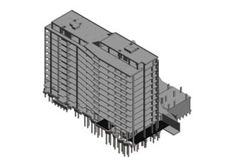
- 8. BLOCK D BLOCK F BLOCK H BLOCK E BLOCK B BLOCK C BLOCK A HOTEL TERMINAL BLOCK G ENDERBY HSE KEY PLAN DPDLDJ DNDK DMDHDC DDDBDA DE DF DG TOU +42.720 m SSL +42.320 m +8.120 m LB1 L00 L01 L02 L03 L04 L05 L06 L07 L08 L09 L10 L11 LRF +42.320 m +39.120 m +35.920 m +32.720 m +29.720 m +26.720 m +23.720 m +20.720 m +17.720 m +14.720 m +11.720 m +8.720 m +5.720 m +2.520 m D8 D9D7D2 D12D11 D5 D4 D6 D1 D10D3 SSL +2.520 m SSL +11.720 m SSL +39.120 m SSL +40.260 m TOU +36.360 m +2.520 m LB1 +5.720 m L00 +8.720 m L01 +11.720 m L02 +14.720 m L03 +17.720 m L04 +20.720 m L05 +23.720 m L06 L07 +26.720 m +29.720 m L08 +32.720 m L09 +35.920 m L10 +39.120 m L11 +42.320 m LRF D8 D9D7 D12D11 D5 D6 D10 SSL +39.120 m SSL +42.320 m SSL +43.460 m TOU +39.520 m TOU +36.360 m +2.660 m +42.720 m +2.520 m LB1 +5.720 m L00 +8.720 m L01 +11.720 m L02 +14.720 m L03 +17.720 m L04 +20.720 m L05 +23.720 m L06 L07 +26.720 m +29.720 m L08 +32.720 m L09 +35.920 m L10 +39.120 m L11 +42.320 m LRF NORTH STAIRS Revision Details By Check Date Suffix Purpose of issue Client Project Title In addition to the hazard/risks normally associated with the types of work detailed on this drawing take note of above. It is assumed that all works on this drawing will be carried out by a competent contractor working, where appropriate, to an appropriate method statement. SAFETY, HEALTH AND ENVIRONMENTAL INFORMATION BOX CONSTRUCTION RISKS MAINTENANCE / CLEANING RISK DEMOLITION RISKS Drawing Title Drawn Checked Approved Date URS Internal Project No. Suitability. Scale @ A1 Zone / Mileage This document has been prepared in accordance with the scope of URS' appointment with its client and is subject to the terms of that appointment. URS accepts no liability for any use of this document other than by its client and only for the purposes for which it was prepared and provided. Only written dimensions shall be used. © URS Infrastructure & Environment UK Limited URS Infrastructure & Environment UK Limited www.ursglobal.com Drawing Number. Rev NOTES St George's House, 5 St George's Road Wimbledon, London SW19 4DR Tel +44 (0)20 8944 3300 Fax +44 (0)20 8944 3301 Designed As indicated 12/01/201606:39:36 ENDERBY WHARF LLP SECTIONS & DETAILS SKD OS PW NOV 2013 47068268 PRELIMINARY ENDERBY WHARF, GREENWICH BLOCK D URS-D-XX-SX-05-0001 AA This drawing is for preliminary purposes only and is subject to amendment during design development. UNDER NO CIRCUMSTANCES MUST THIS DRAWING BE USED FOR CONSTRUCTION PURPOSES 1 : 200 05-0001 - SECTION 1-1 1 : 200 05-0001 - SECTION 2-2 1 : 200 05-0001 - SECTION 3-3 ISOMETRIC VIEW