SlideShare ist ein Scribd-Unternehmen logo
1 von 11
Downloaden Sie, um offline zu lesen
Chapter 2
VLC Technology for Indoor LTE Planning
Spiros Louvros and David Fuschelberger
Abstract Long-term evolution (LTE) indoor coverage, owing to its importance, is
becoming very important for cellular operators lately. In international literature, there
is a lot of research regarding visible light communication (VLC), especially indoor,
to improve the expected throughput. To meet user expectations on operator’s indoor
high-quality services and to provide adequate capacity availability, special issues
have to be studied. Indoor users expect faster Internet with less interference and
healthy environment.
2.1 Introduction
Optical communications have been used in various forms for thousands of years.
Since ancient years to Bell’s Photophone introduced in 1880, people were using
methods such as smoke or light signals in order to optically communicate over long
distances. Finally, a long time later, after the invention of light amplification by
stimulated emission of radiation (LASER) sources and light-emitting diodes (LEDs)
in the 1960s, optical communications quickly revolutionized and spread around the
world.
Today’s optical communication technologies may be categorized into two groups:
fiber optics and free space optics (FSO). The main difference between these two
categories of optical communication technologies is the medium that each of them
uses in order to propagate the data. Fiber optics is based on the optical fiber cable,
which it uses as a medium, whereas FSO achieves the transmission over the air.
They both use either lasers or LEDs as their sources, usually at wavelengths such
as infrared (IR), visible, or ultraviolet (UV). Both technologies have advantages
and disadvantages. Fiber optics, for instance, can achieve much higher data rates
than FSO, whereas FSO on the other hand is capable of achieving data transmission
S. Louvros ( ) · D. Fuschelberger
Department of Telecommunication Systems and Networks (TESYD),
Technological Educational Institute of Messolonghi, Messolonghi, Greece
e-mail: splouvros@gmail.com
D. Fuschelberger
e-mail: d.fuschelberger@gmail.com
N. Sklavos et al. (eds.), System-Level Design Methodologies for Telecommunication, 21
DOI 10.1007/978-3-319-00663-5_2, © Springer International Publishing Switzerland 2014
22 S. Louvros and D. Fuschelberger
to places where either physical connection would be impossible to be deployed
or absence of electromagnetic (EM) radiation is important or requested. Engineers
around the world dealing with FSO fortunately tried to use LEDs at the visible
spectrum as information sources anyway.
Since physics provided us with the information that common incandescent light
bulbs or even the more efficient fluorescent lamps would hardly be appropriate for
that purpose, because of the poor data transmission characteristics of the photons
creating their illumination, the only way of using them as a source for FSO was to
force them to blink, in order to decode every instance of changing light condition
as a bit of information. Apparently, these kind of regular light bulbs could not be
turned on and off more than a few times per second and no longer than a few seconds
before they burned out. Therefore, this method would have had huge disadvantages,
mainly because of data rate limitation and, furthermore, because of the fact that a
blinking light bulb would have been a bad solution for communication in the first
place. Fortunately, engineers focused on visible spectrum LEDs, whose light could
be on–off modulated and used as a data source. One of the main restrictions in on–
off modulation is the incapability of fast switching of solid-state devices, such as
PN LEDs, owing to the rising time limitation. This limitation goes far inside the
operating principles of LED and, to be more precise, back into quantum physics,
where electrons experience a certain reaction time offset (inertia characteristics) in
the presence of alternative voltages. Thus, although LED could be switched on/off
several thousand times per second, this switching time is not enough to achieve thou-
sands of megabits per second bit rate. To overcome such problems, engineers have
proposed implementation of more than one communication channel at the same time.
This solution could be implemented either on the optical domain or on the electrical
driving circuit. On the optical domain, the solution is using different colors, since
one channel’s wavelength would never interfere with the wavelengths of the others.
On the electrical driving circuit, this could be achieved by using either spread spec-
trum techniques (optical code division multiple access (OCDMA)) or multicarrier
(orthogonal frequency-division multiplexing (OFDM)). Nevertheless, still the prob-
lem was the limitation in high data rates or the rise of implementation budget, in
contrast to the high rates of IR sources, which were already achievable. Nowadays,
LED industry has taken huge steps in developing more powerful and qualitative LED
chips. Nowadays, white-colored high-power LED modules, blue LED chips com-
bined with a yellow phosphor, are being used for indoor and outdoor illumination.
Their characteristics regarding power consumption and lifetime are by far better than
those of commonly known incandescent light bulbs or even fluorescent lamps. The
only disadvantage of such LED modules still lies in their price and general imple-
mentation costs, but this fact is believed to rapidly change in the next few years since
the market already shows a tremendous interest in using them for various purposes
(e.g., TVs and displays).
This was the breaking point where a new subcategory of FSO, besides the already
existing IR technology, was born: visible light communication (VLC) or also well
known as wireless light communication (Wi-Li). VLC refers to data communication
over a specific range of the EM spectrum, which is visible to humans. This range
2 VLC Technology for Indoor LTE Planning 23
is measured to be approximately from 400 to 700 nm of wavelength, also known
as “visible spectrum.” The term “VLC” first appeared in 2003, when a small group
of people at Keio University in Japan (Nakagawa Laboratory) started to experiment
with LEDs and photodiodes in order to achieve communication via visible light.
The Nakagawa Lab then, together with some of Japan’s biggest technology firms
(NEC Corp., Panasonic, and Toshiba), formed the so-called Visible Light Commu-
nication Consortium (VLCC). Later, VLCC joined forces with the corresponding
IR Consortium, the Infrared Data Association (IrDA). Since then, a lot of research
activities regarding VLC have been carried out around the world, with the European
Framework Programme (FP) 7 OMEGA project and work done at the University
of Oxford, England, being the most notable among them. Furthermore, the Insti-
tute of Electrical and Electronics Engineers (IEEE) Wireless Personal Area Network
(WPAN) working group (802.15) is already working on the standardization of VLC.
What is the VLC’s ultimate goal? Is it the combination of illuminating an area
and providing data communication at the same time via the same technology? Fur-
thermore, as VLC is referring to visible light, specific health-related issues have
arisen against communication technologies that use radio frequency (RF), such as
the broadly known and used IEEE 802.11x standards.
2.2 History of Visible Communications
One of the first implemented FSO systems was used by the French Military: Chappe’s
Telegraph system (semaphore) consisted of wooden structures mounted 5 m high ev-
ery 11 km, each featuring three movable arms to create 196 different signs with word
and sentence meanings as well as telescopes to observe the signs from neighboring
stations in both directions. In 1 min, a single sign crossed a distance of 135 km.
Lamps attached to the movable arms allowed night-time signaling.
The first experiment of VLC was exhibited by Graham Bell whose system was
called Photophone. A brief description of its operation states that “Bell’s Photophone
made sound waves vibrate a beam of reflected sunlight.” This may nowadays be
understood as a simple kind of modulation. As a matter of fact, this experiment
actually transmitted voice over the air long before the first radio transmission ever
occurred!
During World War II, both Axis and Allies used FSO technology for certain
communication, such as the German Lichtsprechgerät 80 and the American Infrared
Telephony device. In 1955, Zenith introduced the first wireless TV remote control
Flash-Matic Tuning, seen in Fig. 1.4. This system used photoelectric cells in the
four corners of the screen in order to control on/off, mute, and channel selection.
Although, 1 year later, ultrasound technology replaced the light system, IR remote
control is still common ever since. RONJA is a user-controlled technology project of
an optical point-to-point (or point-to-multipoint) data link first deployed in Prague,
Czech Republic, in 2001. The link has a 1.4 km range and a stable 10 Mbps full-
duplex data rate.You can mount RONJA on your house and connect your PC or any
other networking device to it. All documents for a do-it-yourself project are available
for free under the GNU license.
24 S. Louvros and D. Fuschelberger
As a conclusion of this small reference to some particular points in the history of
VLC and FSO in general, one could say that this category of communication mediums
has always been popular or at least considered in any way, and may be useful in many
different applications in the future. Furthermore, by considering its advantages over
other currently common wireless communication technologies, VLC seems to be
here to stay.
2.3 Visible Light Communications: General Review
Wireless optical communication networks, when appropriately studied, developed,
and optimized, could provide a reliable, high-security, interference-insensitive,
and especially for elders and health-sensitive people, biologically friendly indoor
communication and monitoring network. This network would allow the creation
and expansion of seamless computing applications, telemetry, and medical sensor
monitoring using large bandwidth high-frequency pulsed light instead of RFs and mi-
crowaves. VLC technology uses modulated light, emitted and received by LEDs for
downlink and IR LEDs for uplink path. Both uplink and downlink could be provided
sufficiently. IEEE has been working on standardization of VLC since 2009 in the
context of WPANs (802.15) and recently provided a draft standard for short-range
wireless optical communication using visible light, including full medium access
control (MAC) and physical (PHY) layer protocols.
2.3.1 VLC: Advantages and Disadvantages
VLC is not, however, the unique existing technology for wireless optical communica-
tions. Other existing and well-appreciated radio technologies are ZigBee, Bluetooth,
and WiFi. Although, nowadays radio technologies are the most dominant owing
to their market penetration, especially for indoor applications, solid-state illumina-
tion technology with intensive LEDs (power LEDs) has been developed and found
increasing market growth, because it reduces significant power consumption to-
gether with expanding architectural capabilities. It is profound that LED provides
a good performance of cost versus brightness against other illumination devices
[1]. LED usage (actually the whole wireless optical solution) may help in provid-
ing many services—indoor residence illumination, indoor and outdoor line-of-sight
communications, area security functions, telemetry applications, and remote med-
ical monitoring. It is well known that WiFi technology is the most dominant and
worldwide respected and accepted technology among all other radio technologies
[2]. In most criteria, VLC and WiFi are complementary on performance and in some
aspects (power availability, Tx/Rx power, security, and data density) VLC is even
superior. WiFi could be superior on range and non-line-of-sight (NLOS) radio link
environments. Indeed, VLC suffers from shadowing and atmospheric absorption,
2 VLC Technology for Indoor LTE Planning 25
Fig. 2.1 Comparison among LTE and other existing optical wireless technologies
thus restricting its high data rate applications to short-distance communication links
[1]. However, by providing appropriate indoor illumination planning and number of
LED lamps in the indoor design, range will always be sufficiently small to provide
enough signal strength on receiver and NLOS will never be the case. Moreover, for
sufficient ranges and after proper illumination design and multiple LED arrays in the
building ceiling, data rate performance is comparable to all radio technologies since
distance will be eliminated owing to LED array reuse factor. To test the performance
of VLC technology in several ranges, a simple PHY layer VLC prototype has been
implemented, as part of undergraduate student thesis, in the Telecom Laboratories
of the Department of Telecommunication Systems and Networks of Technological
Educational Institute of Messolonghi. This prototype was only a simple implementa-
tion, meaning that it was not protected against visible light interference. Furthermore,
neither preample electrical filter nor channel equalizer to fight back intersymbol in-
terference (ISI) and multipath channel fadings was implemented. Under several test
measurements, bit rates of 1 Mbps have been demonstrated [3]. Concluding about
data rates and ranges, VLC, under appropriate illumination design and LED array
distance reuse, provides superior performances over short-range radio technology
competitors such as ZigBee and Bluetooth (Fig. 2.1).
The raising issue of interference of background light sources could be easily
eliminated by using appropriate optical filters, a well-known technique proposed in
several applications, like OMEGA FP7 project [4]. Available bandwidth, interfer-
ence, and security are other issues in which VLC is considered to be superior as it
can provide both partial and full solutions to a number of wireless radio environment
technological problems. Such solutions include the increasingly limited availability
of conventional RF bandwidths for electronic equipment, the possible communi-
cations interference with sensitive electrical equipment, and the door-to-door data
security [1].
26 S. Louvros and D. Fuschelberger
The perceived negative health consequences of existing radio technologies [1], as
indicated in Fig. 2.5, when exposed to high RF and microwave levels—especially
for health-sensitive human groups or buildings (schools, hospitals)—is a severe is-
sue. From health perspective, all such applications and solutions might relax indoor
space from radio emissions of contemporary telecommunication systems (WiFi,
WiMax, Bluetooth, and UWB), which in certain cases are prohibitive (e.g., hospi-
tals, airplanes, and areas inhabited by elderly people) or nondesirable (e.g., schools,
university class rooms). Consequently, by replacing existing microwave-based and
radio-based wireless networks, a next-generation green wireless communication net-
work that will transform our everyday experiences and contribute to the idea of cyber
green communication networks is obtained.
Moreover, in addition to all previously mentioned metrics, there is also one major
advantage of optical VLC technology compared to any radio competitor. This ad-
vantage is the OFDM compatibility and superiority over VLC [5]. Indeed, OFDM
enables very high data rate transmission with low computational complexity at the
receiver since it is robust to multipath propagation. OFDM entirely eliminates the
need for complex algorithms to cope with ISI, which typically gets worse with higher
data rates. However, a standard OFDM transmitter produces a complex-valued sig-
nal. Through a simple mathematical “trick,” this signal can be converted into a
real-valued signal whose amplitude greatly varies in time. As a consequence, the
peak-to-average-ratio (PAR) is high. This causes concerns in RF communications
because of the detrimental impact on system performance due to power amplifier
nonlinearities. For optical wireless communications, this effect, however, can be
turned into an advantage as the high PAR signal can be exploited for intensity mod-
ulation [6]. Given that the minimum illumination for reading purposes is 400 lx,
and that this already translates into a signal-to-noise ratio (SNR) greater than 30
dB, OFDM combined with higher-order modulation techniques, such as M-level
quadrature amplitude modulation (QAM), results in a powerful transmission tech-
nology for incoherent visible light sources. D-Light team, University of Edinburgh,
has demonstrated real-time data transmission using off-the-shelf LEDs of 130 Mbps.
Finally, one last advantage ofVLC compared to any other available radio technology
competitor is the interference issue. Using VLC over OFDM results in high link-
level data rates, making VLC a very good candidate over OFDM for indoor LTE
implementation.
There is, however, one good question to be answered; what happens if multiple
transmitters are deployed which together form an optical cellular network? In a recent
publication [7], the area spectral efficiency (ASE) of future interference-limited
wireless systems has been determined. The ASE is a measure of the maximum data
rate per unit and per hertz bandwidth. It assumes a wireless network that is composed
of multiple randomly deployed access points where each access point uses the same
transmission resource/bandwidth. Basically, many access points means a high reuse
of the same transmission resource and thus high data rate per unit area, but at a
certain point this gain is outweighed by increased interference, which results in a
drop in ASE. On the other hand, if there are only a few access points, this means a
low resource reuse and, hence, low data rate per unit area, but also low interference.
2 VLC Technology for Indoor LTE Planning 27
Table 2.1 Advantages and disadvantages of VLC technology
Advantages Disadvantages
Harmless for the human body Atmospheric absorption
Data transmission by sockets of existing light
fixtures
Shadowing/signal deterioration
Alleviation of problems associated with radio
frequency (RF) communication systems
Beam dispersion
Far less energy consumption Interference from background light sources
Increased security
Compact integration on sensors through small
dimensions
No communication if no “line of sight”
Huge number of channels available without
interfering with other sources
Only discrete spectrum available as light source
and sensor
Simple electronics as drive for the LEDs Noise from interference of other sources has to
be filtered
No influence to other sensitive equipment
through radio waves
Therefore, there is an optimum point for the ASE. This optimum ASE for an indoor
environment is found to be 4 × 10⁻⁴
bits/s/Hz/m2
.
Implementing cellular networks and presumably LTE over VLC technology has,
among other aforementioned advantages, the benefit of security and privacy. In-
deed, using VLC technology, there will be no interference for indoor applications
among rooms as rooms are typically separated by walls and light does not prop-
agate through walls; an option, which does not hold in case of RF signals. If we
assume a typical room of the size 4 m × 4 m = 16 m2
, and a VLC transmitter that is
capable of delivering 130 Mbps with an off-the-shelf LED lamp of 20 MHz band-
width, as demonstrated by the D-Light team, this would result inASE of: 130 × 106
[bits/s]/(20 × 106
[Hz] × 16 m2
) = 0.41 bits/s/Hz/m2
.
Comparing this result to the maximum 0.0004 bits/s/Hz/m2
for state-of-the-art
wireless systems, we can observe a 1,025 times higher ASE. This essentially means
thatVLC technology has the potential to provide wireless Gbps indoor services (over,
of course, short ranges of 1–10 m) using standard off-the-shelf LEDs. This results
in a massive RF spectrum relief, which frees up RF resources for the provision of
better services in areas where VLC technology is difficult to use such as in remote
areas. Taking this idea further and exploiting particular LED light radiation charac-
teristics from different light sources in a room coexistence scenario, the expected
ASE improvement could reach well beyond the factor of 2,000 and more.
Concluding, VLC seems to be complementary and in some aspects superior to
radio technologies. WiFi might be used for wide-area coverage within a building and
ZigBee for short-range communications. However, interference, unlimited band-
width, health issues, OFDM, and security support the VLC application and data
rates could be in adequate level using many VLC LED arrays for short- to medium-
range indoor communications. Table 2.1 presents the major pros and cons of the
VLC technology.
28 S. Louvros and D. Fuschelberger
2.3.2 VLC: Innovation and Standards
Although VLC concept has its origin back to year 1880 and Alexander Graham Bell
[8], the first steps of a communication system using visible light while serving il-
lumination requirements of indoor spaces were made at the end of last century [9].
Since then, several research groups have shown great interest in modeling, analyzing,
and developing prototypes in order to assess the feasibility and the performance of a
VLC system. In this context, the work of Nakagawa Laboratory of Keio University
was pioneering and boosted the interest in VLC [10–14]. This work led to the es-
tablishment of the VLCC Japan in 2003, which provided the first standards (JEITA
CP-1221 and CP-1222) for VLC systems in 2007.
The key component of VLC systems is an LED radiating visible light, which is
properly modulated for transmission information, while retaining its illumination
capability. White-light LEDs are the most promising ones from illumination and
communication point of view. Most research work and experiments are based on
phosphorescent white LED, which consists of a blue LED chip covered with a layer
of yellow phosphor. These chips are of low cost and have simpler driving, but they
present a low modulation bandwidth (2–3 MHz). Proper blue-filtering before the
detector allows only blue component of white light, thus increasing the bandwidth
to the order of 20 MHz [15, 16] with a total achievable bit rate of 100 Mbps using
discrete multitone transmission (DMT). Channel equalization techniques have also
been proposed [17, 18] for further bandwidth enhancement. A good achievement
of 500 Mbps over a 5 m distance has been announced in 2010 from Heinrich Hertz
Institute and Siemens [19].
Since 2010,VLC has been standardized by IEEE in the context ofWPAN (802.15)
[20] for short-range wireless optical communication using visible light, including
full MAC and PHY layer protocols. IEEE specifies three PHY layer modes: PHY I
for outdoor usage, low data rate applications, on–off keying (OOK) with Manchester
line coding and variable pulse position modulation (VPPM) with 4B6B line coding,
data rates in the tens to hundreds of kbps, and RS outer coding; PHY II for indoor
usage, moderate data rate applications, OOK with 8B10B line coding andVPPM with
4B6B line coding, data rates varying from 1.25 to 96 Mbps, and RS coding; PHY III
for indoor high rate applications using color shift keying (CSK) with multiple light
sources and detectors, supported data rates up to 96 Mbps, using RS coding.
Important work has also been performed by the hOME GigabitAccess (OMEGA)
project [4], funded by the European Union within FP7. The project ended by March
2011 with the development of a fullVLC prototype for video broadcasting and a gen-
eral MAC protocol for home environments for IR, VLC, power line communications
(PLC), and RF PHY layers interoperability.
2.4 LTE Implementation Over VLC: Technical Review
Regarding the general concept of VLC, as already mentioned, a primary future
vision of successful implementation and usage would be the combination of LED
illumination along with data access. This is what makes VLC more promising with
2 VLC Technology for Indoor LTE Planning 29
Fig. 2.2 VLC indoor LTE coverage implementation proposal
regard to its family FSO: the fact that the medium itself may be used for additional
purposes in parallel.
Figure 2.2 presents the LTE indoor coverage over LTE technology proposal. VLC
advantages and standards have already been presented. In such an implementation,
indoor planners could make use of several existing technologies for advanced ap-
plications and purposes [21]. From outdoor cellular operator network to the indoor
coverage glass, single-mode (SM) optical fibers should be used and appropriate
capacity planning should be performed to provide appropriate bandwidth for opti-
cal Ethernet transmission. Inside buildings, polymer optical fibers could be used as
a cheaper solution for the optical signal distribution. Optical distributors/splitters
should be provided to distribute optical signal throughout building floors and rooms.
Finally, LEDs with appropriate driving circuit and optical to electrical converters
should also be used as the indoor distribution and illumination system.
2.4.1 Glass Optical Fiber
According to standards, LTE ideally needs Ethernet links over fiber optics. Opti-
cal fiber planning includes several stages. A wide variety of specifications shall be
used at an early stage. Regarding the physical medium, system topology should be
considered including cable location and/or cable routes. Existing cable protection
should be carefully examined (none, building ducts, or underground ducts). Cable
specifications should follow standards (fiber, moisture ingression) and number of
fibers per cable shall be considered and defined. Regarding network issues, network
applications and proposed topology shall be finalized together with transmission
standards (SDH, SONET), available Ethernet bit rates, coding, and multiplexing.
30 S. Louvros and D. Fuschelberger
Fig. 2.3 Power budget calculation including margins and losses
Specifically for the fiber itself, several parameters and characteristics have to be de-
cided. First of all, it has to be decided whether multimode (MM) or SM shall be used,
also the core size and fiber numerical aperture (NA), appropriate fiber attenuation
for the link have to be determined, and budget calculations have to be done. Also,
based on Ethernet-supported bit rate, fiber dispersion, including all tolerances, shall
be considered. Mostly, on metropolitan networks, connectors and splitters are used
quite often. For this reason, considerations on connector types, connector losses and
reflections, available tolerances, mechanical or fusion splices, loss and tolerances
and termination enclosures, and patch panel losses have to be calculated on link
budget.
When planning is performed, always the worst case is considered, calculating
also tolerances. As an example, assume the worst case transmitter output power is
− 12 dBm and the worst case receiver input power needed is − 30 dBm. Then, power
budget = − 12 dBm − (− 30 dBm) = 18 dB of attenuation is possible over the link
before failure (nonavailability) occurs. To find maximum available fiber attenuation,
we substitute from available 18 dB budget the expected loss due to connectors (con-
nector attenuations 1 dB per connector) and splices (splice attenuation 1.5 dB per
splicing) and we are left with total allowed fiber attenuation of 12.8 dB. However,
this is not always enough. Indeed, we shall also add expected margins due to fiber
aging (the typical operating lifetime of a communication transmission system may be
as high as 20–30 years), extra future splices, extra fiber length in future operator, and
maintenance repairing and extra upgrades in the bit rate or advances in multiplexing.
Figure 2.3 presents an example of power budget calculation including all losses and
expected margins.
In order to get a more sophisticated optical fiber planning, power penalties should
be included in the analysis. Power penalty is indeed the initial calculated power
increment in order to eliminate any undesired effects from expected system noise
or system distortion. Most common penalties are calculated owing to fiber disper-
sion effects and fiber attenuation. There are two dominant fiber dispersions, time
http://www.springer.com/978-3-319-00662-8

Weitere ähnliche Inhalte

Was ist angesagt?

VISIBLELIGHT COMMUNICATION AND LI-FI
VISIBLELIGHT COMMUNICATION AND LI-FIVISIBLELIGHT COMMUNICATION AND LI-FI
VISIBLELIGHT COMMUNICATION AND LI-FImes college
 
Thesis presentation on Visible light communication
Thesis presentation on Visible light communicationThesis presentation on Visible light communication
Thesis presentation on Visible light communicationশুভরাজ পাল
 
Woban Prototype Ieee Network
Woban Prototype Ieee NetworkWoban Prototype Ieee Network
Woban Prototype Ieee NetworkShahab Shahid
 
Visible Light Communication
Visible Light CommunicationVisible Light Communication
Visible Light CommunicationIJERD Editor
 
Optical wireless communication
Optical wireless communicationOptical wireless communication
Optical wireless communicationVishak V Thampy
 
Visible Light Communication
Visible Light CommunicationVisible Light Communication
Visible Light CommunicationAshwin Shenoy M
 
Seminar on vlc / visible light communication
Seminar on vlc / visible light communicationSeminar on vlc / visible light communication
Seminar on vlc / visible light communicationSAMBIT SWAIN
 
Visible Light communication
Visible Light communicationVisible Light communication
Visible Light communicationJay Lohokare
 
Optical Wireless Communications - from the space to the chip.
Optical Wireless Communications - from the space to the chip.Optical Wireless Communications - from the space to the chip.
Optical Wireless Communications - from the space to the chip.Joaquin Perez
 
wireless optical communication
wireless optical communicationwireless optical communication
wireless optical communicationGNS Manikanta
 
Practical Fibre Optics and Interfacing Techniques to Industrial Ethernet and ...
Practical Fibre Optics and Interfacing Techniques to Industrial Ethernet and ...Practical Fibre Optics and Interfacing Techniques to Industrial Ethernet and ...
Practical Fibre Optics and Interfacing Techniques to Industrial Ethernet and ...Living Online
 
transmission media in computer network
transmission media in computer networktransmission media in computer network
transmission media in computer networkAnsh Aggarwal
 
Visible light communication
Visible light communicationVisible light communication
Visible light communicationParth Saxena
 

Was ist angesagt? (19)

VISIBLELIGHT COMMUNICATION AND LI-FI
VISIBLELIGHT COMMUNICATION AND LI-FIVISIBLELIGHT COMMUNICATION AND LI-FI
VISIBLELIGHT COMMUNICATION AND LI-FI
 
Thesis presentation on Visible light communication
Thesis presentation on Visible light communicationThesis presentation on Visible light communication
Thesis presentation on Visible light communication
 
Woban Prototype Ieee Network
Woban Prototype Ieee NetworkWoban Prototype Ieee Network
Woban Prototype Ieee Network
 
Visible Light Communication
Visible Light CommunicationVisible Light Communication
Visible Light Communication
 
Optical wireless communication
Optical wireless communicationOptical wireless communication
Optical wireless communication
 
Visible Light Communication
Visible Light CommunicationVisible Light Communication
Visible Light Communication
 
Seminar on vlc / visible light communication
Seminar on vlc / visible light communicationSeminar on vlc / visible light communication
Seminar on vlc / visible light communication
 
Visible Light communication
Visible Light communicationVisible Light communication
Visible Light communication
 
Freespaceoptics
FreespaceopticsFreespaceoptics
Freespaceoptics
 
Suman Jlt
Suman JltSuman Jlt
Suman Jlt
 
Vlc term paper
Vlc term paperVlc term paper
Vlc term paper
 
Optical Wireless Communications - from the space to the chip.
Optical Wireless Communications - from the space to the chip.Optical Wireless Communications - from the space to the chip.
Optical Wireless Communications - from the space to the chip.
 
wireless optical communication
wireless optical communicationwireless optical communication
wireless optical communication
 
Practical Fibre Optics and Interfacing Techniques to Industrial Ethernet and ...
Practical Fibre Optics and Interfacing Techniques to Industrial Ethernet and ...Practical Fibre Optics and Interfacing Techniques to Industrial Ethernet and ...
Practical Fibre Optics and Interfacing Techniques to Industrial Ethernet and ...
 
transmission media in computer network
transmission media in computer networktransmission media in computer network
transmission media in computer network
 
Visible light communication
Visible light communicationVisible light communication
Visible light communication
 
Optical communication
Optical communicationOptical communication
Optical communication
 
Report
ReportReport
Report
 
33
3333
33
 

Andere mochten auch

Ficha funções blog revisões para o teste maio
Ficha  funções blog revisões para o teste maioFicha  funções blog revisões para o teste maio
Ficha funções blog revisões para o teste maioDocas Vivas
 
Ficha de trabalho 3
Ficha de trabalho 3Ficha de trabalho 3
Ficha de trabalho 3Ana Madeira
 
Setor sucroenergético perde um grande mestre
Setor sucroenergético perde um grande mestreSetor sucroenergético perde um grande mestre
Setor sucroenergético perde um grande mestreAgricultura Sao Paulo
 
Circular 01 1415
Circular 01 1415Circular 01 1415
Circular 01 1415agr740
 
हिरोशिमा
हिरोशिमाहिरोशिमा
हिरोशिमाathiraamal
 
Circular 02 1415
Circular 02 1415Circular 02 1415
Circular 02 1415agr740
 
Escuta holística
Escuta holísticaEscuta holística
Escuta holísticaCleoalvares
 
Makalah pengertian pendidikan dan tujuannya
Makalah pengertian pendidikan dan tujuannyaMakalah pengertian pendidikan dan tujuannya
Makalah pengertian pendidikan dan tujuannyaMara Sutan Siregar
 

Andere mochten auch (12)

Ficha funções blog revisões para o teste maio
Ficha  funções blog revisões para o teste maioFicha  funções blog revisões para o teste maio
Ficha funções blog revisões para o teste maio
 
Portadores de texto e atividades
Portadores de texto e atividadesPortadores de texto e atividades
Portadores de texto e atividades
 
Ficha de trabalho 3
Ficha de trabalho 3Ficha de trabalho 3
Ficha de trabalho 3
 
Setor sucroenergético perde um grande mestre
Setor sucroenergético perde um grande mestreSetor sucroenergético perde um grande mestre
Setor sucroenergético perde um grande mestre
 
Circular 01 1415
Circular 01 1415Circular 01 1415
Circular 01 1415
 
Eventos
EventosEventos
Eventos
 
हिरोशिमा
हिरोशिमाहिरोशिमा
हिरोशिमा
 
Eventos
EventosEventos
Eventos
 
Circular 02 1415
Circular 02 1415Circular 02 1415
Circular 02 1415
 
Escuta holística
Escuta holísticaEscuta holística
Escuta holística
 
Makalah pengertian pendidikan dan tujuannya
Makalah pengertian pendidikan dan tujuannyaMakalah pengertian pendidikan dan tujuannya
Makalah pengertian pendidikan dan tujuannya
 
imoveis de Luxo Goiania
imoveis de Luxo Goianiaimoveis de Luxo Goiania
imoveis de Luxo Goiania
 

Ähnlich wie VLC Tech for Indoor LTE Planning

7 Visible Light Communication
7 Visible Light Communication7 Visible Light Communication
7 Visible Light CommunicationAnita Miller
 
01-Overview of Optical Fiber Communication.pptx
01-Overview of Optical Fiber Communication.pptx01-Overview of Optical Fiber Communication.pptx
01-Overview of Optical Fiber Communication.pptxAkliluAyele3
 
Li Fi seminar report
Li Fi seminar reportLi Fi seminar report
Li Fi seminar reportvishalhasnani
 
Implementation of li_fi_using_arduino
Implementation of li_fi_using_arduinoImplementation of li_fi_using_arduino
Implementation of li_fi_using_arduinoVivek Bakul Maru
 
Engineering Project Intern Report Format
Engineering Project Intern Report FormatEngineering Project Intern Report Format
Engineering Project Intern Report FormatChin2uuu
 
Mitigating effect of flickering and dimming in visible light communication us...
Mitigating effect of flickering and dimming in visible light communication us...Mitigating effect of flickering and dimming in visible light communication us...
Mitigating effect of flickering and dimming in visible light communication us...IISRT
 
Iisrt 2-mitigating effect of flickering and dimming in visible light communic...
Iisrt 2-mitigating effect of flickering and dimming in visible light communic...Iisrt 2-mitigating effect of flickering and dimming in visible light communic...
Iisrt 2-mitigating effect of flickering and dimming in visible light communic...IISRTJournals
 
Mitigating effect of flickering and dimming in visible light communication us...
Mitigating effect of flickering and dimming in visible light communication us...Mitigating effect of flickering and dimming in visible light communication us...
Mitigating effect of flickering and dimming in visible light communication us...Ramesh Patriotic
 
A Master of ScienceProject Report Optical cmms-oaa516
A Master of ScienceProject Report Optical cmms-oaa516A Master of ScienceProject Report Optical cmms-oaa516
A Master of ScienceProject Report Optical cmms-oaa516Olufisayo Adekile
 
Practical Fibre Optics for Engineers and Technicians
Practical Fibre Optics for Engineers and TechniciansPractical Fibre Optics for Engineers and Technicians
Practical Fibre Optics for Engineers and TechniciansLiving Online
 
Practical fibre Optics for Engineers and Technicians
Practical fibre Optics for Engineers and TechniciansPractical fibre Optics for Engineers and Technicians
Practical fibre Optics for Engineers and TechniciansLiving Online
 
Practical Fibre Optics for Engineers and Technicians
Practical Fibre Optics for Engineers and TechniciansPractical Fibre Optics for Engineers and Technicians
Practical Fibre Optics for Engineers and TechniciansLiving Online
 
Exploring Fiber Optic Cable: Structure, Functionality and Applications | GQ R...
Exploring Fiber Optic Cable: Structure, Functionality and Applications | GQ R...Exploring Fiber Optic Cable: Structure, Functionality and Applications | GQ R...
Exploring Fiber Optic Cable: Structure, Functionality and Applications | GQ R...GQ Research
 
OPTICAL COMMUNICATION SYSTEM
OPTICAL COMMUNICATION SYSTEMOPTICAL COMMUNICATION SYSTEM
OPTICAL COMMUNICATION SYSTEMAarthiAarthi22
 
Practical Fibre Optics & Interfacing Techniques to Industrial Ethernet and Wi...
Practical Fibre Optics & Interfacing Techniques to Industrial Ethernet and Wi...Practical Fibre Optics & Interfacing Techniques to Industrial Ethernet and Wi...
Practical Fibre Optics & Interfacing Techniques to Industrial Ethernet and Wi...Living Online
 

Ähnlich wie VLC Tech for Indoor LTE Planning (20)

Lifi report
Lifi reportLifi report
Lifi report
 
7 Visible Light Communication
7 Visible Light Communication7 Visible Light Communication
7 Visible Light Communication
 
01-Overview of Optical Fiber Communication.pptx
01-Overview of Optical Fiber Communication.pptx01-Overview of Optical Fiber Communication.pptx
01-Overview of Optical Fiber Communication.pptx
 
Li Fi seminar report
Li Fi seminar reportLi Fi seminar report
Li Fi seminar report
 
free space optics
 free space optics free space optics
free space optics
 
Fso
FsoFso
Fso
 
Implementation of li_fi_using_arduino
Implementation of li_fi_using_arduinoImplementation of li_fi_using_arduino
Implementation of li_fi_using_arduino
 
OPTICAL COMMUNICATION
OPTICAL COMMUNICATIONOPTICAL COMMUNICATION
OPTICAL COMMUNICATION
 
Engineering Project Intern Report Format
Engineering Project Intern Report FormatEngineering Project Intern Report Format
Engineering Project Intern Report Format
 
Mitigating effect of flickering and dimming in visible light communication us...
Mitigating effect of flickering and dimming in visible light communication us...Mitigating effect of flickering and dimming in visible light communication us...
Mitigating effect of flickering and dimming in visible light communication us...
 
Iisrt 2-mitigating effect of flickering and dimming in visible light communic...
Iisrt 2-mitigating effect of flickering and dimming in visible light communic...Iisrt 2-mitigating effect of flickering and dimming in visible light communic...
Iisrt 2-mitigating effect of flickering and dimming in visible light communic...
 
Mitigating effect of flickering and dimming in visible light communication us...
Mitigating effect of flickering and dimming in visible light communication us...Mitigating effect of flickering and dimming in visible light communication us...
Mitigating effect of flickering and dimming in visible light communication us...
 
A Master of ScienceProject Report Optical cmms-oaa516
A Master of ScienceProject Report Optical cmms-oaa516A Master of ScienceProject Report Optical cmms-oaa516
A Master of ScienceProject Report Optical cmms-oaa516
 
Practical Fibre Optics for Engineers and Technicians
Practical Fibre Optics for Engineers and TechniciansPractical Fibre Optics for Engineers and Technicians
Practical Fibre Optics for Engineers and Technicians
 
Practical fibre Optics for Engineers and Technicians
Practical fibre Optics for Engineers and TechniciansPractical fibre Optics for Engineers and Technicians
Practical fibre Optics for Engineers and Technicians
 
Practical Fibre Optics for Engineers and Technicians
Practical Fibre Optics for Engineers and TechniciansPractical Fibre Optics for Engineers and Technicians
Practical Fibre Optics for Engineers and Technicians
 
Exploring Fiber Optic Cable: Structure, Functionality and Applications | GQ R...
Exploring Fiber Optic Cable: Structure, Functionality and Applications | GQ R...Exploring Fiber Optic Cable: Structure, Functionality and Applications | GQ R...
Exploring Fiber Optic Cable: Structure, Functionality and Applications | GQ R...
 
OPTICAL COMMUNICATION SYSTEM
OPTICAL COMMUNICATION SYSTEMOPTICAL COMMUNICATION SYSTEM
OPTICAL COMMUNICATION SYSTEM
 
Practical Fibre Optics & Interfacing Techniques to Industrial Ethernet and Wi...
Practical Fibre Optics & Interfacing Techniques to Industrial Ethernet and Wi...Practical Fibre Optics & Interfacing Techniques to Industrial Ethernet and Wi...
Practical Fibre Optics & Interfacing Techniques to Industrial Ethernet and Wi...
 
Blackbook LIFI final
Blackbook LIFI finalBlackbook LIFI final
Blackbook LIFI final
 

Mehr von Spiros Louvros

Selected papers-2014 Topology Conference
Selected papers-2014 Topology ConferenceSelected papers-2014 Topology Conference
Selected papers-2014 Topology ConferenceSpiros Louvros
 
Analytical average throughput and delay estimations for LTE
Analytical average throughput and delay estimations for LTEAnalytical average throughput and delay estimations for LTE
Analytical average throughput and delay estimations for LTESpiros Louvros
 
IEEE CAMAD 2014_LTE Uplink Delay Constraints for Smart Grid Applications
IEEE CAMAD 2014_LTE Uplink Delay Constraints for Smart Grid ApplicationsIEEE CAMAD 2014_LTE Uplink Delay Constraints for Smart Grid Applications
IEEE CAMAD 2014_LTE Uplink Delay Constraints for Smart Grid ApplicationsSpiros Louvros
 
IoT M2M case study analysis
IoT M2M case study analysisIoT M2M case study analysis
IoT M2M case study analysisSpiros Louvros
 
IEEE ομιλία_τελικό
IEEE ομιλία_τελικόIEEE ομιλία_τελικό
IEEE ομιλία_τελικόSpiros Louvros
 

Mehr von Spiros Louvros (10)

Selected papers-2014 Topology Conference
Selected papers-2014 Topology ConferenceSelected papers-2014 Topology Conference
Selected papers-2014 Topology Conference
 
Analytical average throughput and delay estimations for LTE
Analytical average throughput and delay estimations for LTEAnalytical average throughput and delay estimations for LTE
Analytical average throughput and delay estimations for LTE
 
IEEE CAMAD 2014
IEEE CAMAD 2014IEEE CAMAD 2014
IEEE CAMAD 2014
 
IEEE CAMAD 2014_LTE Uplink Delay Constraints for Smart Grid Applications
IEEE CAMAD 2014_LTE Uplink Delay Constraints for Smart Grid ApplicationsIEEE CAMAD 2014_LTE Uplink Delay Constraints for Smart Grid Applications
IEEE CAMAD 2014_LTE Uplink Delay Constraints for Smart Grid Applications
 
LTE Air Interface
LTE Air InterfaceLTE Air Interface
LTE Air Interface
 
9783319006628-c1
9783319006628-c19783319006628-c1
9783319006628-c1
 
IoT M2M case study analysis
IoT M2M case study analysisIoT M2M case study analysis
IoT M2M case study analysis
 
IEEE ομιλία_τελικό
IEEE ομιλία_τελικόIEEE ομιλία_τελικό
IEEE ομιλία_τελικό
 
Radio Link budget
Radio Link budgetRadio Link budget
Radio Link budget
 
Kaufman roberts paper
Kaufman roberts paperKaufman roberts paper
Kaufman roberts paper
 

VLC Tech for Indoor LTE Planning

  • 1. Chapter 2 VLC Technology for Indoor LTE Planning Spiros Louvros and David Fuschelberger Abstract Long-term evolution (LTE) indoor coverage, owing to its importance, is becoming very important for cellular operators lately. In international literature, there is a lot of research regarding visible light communication (VLC), especially indoor, to improve the expected throughput. To meet user expectations on operator’s indoor high-quality services and to provide adequate capacity availability, special issues have to be studied. Indoor users expect faster Internet with less interference and healthy environment. 2.1 Introduction Optical communications have been used in various forms for thousands of years. Since ancient years to Bell’s Photophone introduced in 1880, people were using methods such as smoke or light signals in order to optically communicate over long distances. Finally, a long time later, after the invention of light amplification by stimulated emission of radiation (LASER) sources and light-emitting diodes (LEDs) in the 1960s, optical communications quickly revolutionized and spread around the world. Today’s optical communication technologies may be categorized into two groups: fiber optics and free space optics (FSO). The main difference between these two categories of optical communication technologies is the medium that each of them uses in order to propagate the data. Fiber optics is based on the optical fiber cable, which it uses as a medium, whereas FSO achieves the transmission over the air. They both use either lasers or LEDs as their sources, usually at wavelengths such as infrared (IR), visible, or ultraviolet (UV). Both technologies have advantages and disadvantages. Fiber optics, for instance, can achieve much higher data rates than FSO, whereas FSO on the other hand is capable of achieving data transmission S. Louvros ( ) · D. Fuschelberger Department of Telecommunication Systems and Networks (TESYD), Technological Educational Institute of Messolonghi, Messolonghi, Greece e-mail: splouvros@gmail.com D. Fuschelberger e-mail: d.fuschelberger@gmail.com N. Sklavos et al. (eds.), System-Level Design Methodologies for Telecommunication, 21 DOI 10.1007/978-3-319-00663-5_2, © Springer International Publishing Switzerland 2014
  • 2. 22 S. Louvros and D. Fuschelberger to places where either physical connection would be impossible to be deployed or absence of electromagnetic (EM) radiation is important or requested. Engineers around the world dealing with FSO fortunately tried to use LEDs at the visible spectrum as information sources anyway. Since physics provided us with the information that common incandescent light bulbs or even the more efficient fluorescent lamps would hardly be appropriate for that purpose, because of the poor data transmission characteristics of the photons creating their illumination, the only way of using them as a source for FSO was to force them to blink, in order to decode every instance of changing light condition as a bit of information. Apparently, these kind of regular light bulbs could not be turned on and off more than a few times per second and no longer than a few seconds before they burned out. Therefore, this method would have had huge disadvantages, mainly because of data rate limitation and, furthermore, because of the fact that a blinking light bulb would have been a bad solution for communication in the first place. Fortunately, engineers focused on visible spectrum LEDs, whose light could be on–off modulated and used as a data source. One of the main restrictions in on– off modulation is the incapability of fast switching of solid-state devices, such as PN LEDs, owing to the rising time limitation. This limitation goes far inside the operating principles of LED and, to be more precise, back into quantum physics, where electrons experience a certain reaction time offset (inertia characteristics) in the presence of alternative voltages. Thus, although LED could be switched on/off several thousand times per second, this switching time is not enough to achieve thou- sands of megabits per second bit rate. To overcome such problems, engineers have proposed implementation of more than one communication channel at the same time. This solution could be implemented either on the optical domain or on the electrical driving circuit. On the optical domain, the solution is using different colors, since one channel’s wavelength would never interfere with the wavelengths of the others. On the electrical driving circuit, this could be achieved by using either spread spec- trum techniques (optical code division multiple access (OCDMA)) or multicarrier (orthogonal frequency-division multiplexing (OFDM)). Nevertheless, still the prob- lem was the limitation in high data rates or the rise of implementation budget, in contrast to the high rates of IR sources, which were already achievable. Nowadays, LED industry has taken huge steps in developing more powerful and qualitative LED chips. Nowadays, white-colored high-power LED modules, blue LED chips com- bined with a yellow phosphor, are being used for indoor and outdoor illumination. Their characteristics regarding power consumption and lifetime are by far better than those of commonly known incandescent light bulbs or even fluorescent lamps. The only disadvantage of such LED modules still lies in their price and general imple- mentation costs, but this fact is believed to rapidly change in the next few years since the market already shows a tremendous interest in using them for various purposes (e.g., TVs and displays). This was the breaking point where a new subcategory of FSO, besides the already existing IR technology, was born: visible light communication (VLC) or also well known as wireless light communication (Wi-Li). VLC refers to data communication over a specific range of the EM spectrum, which is visible to humans. This range
  • 3. 2 VLC Technology for Indoor LTE Planning 23 is measured to be approximately from 400 to 700 nm of wavelength, also known as “visible spectrum.” The term “VLC” first appeared in 2003, when a small group of people at Keio University in Japan (Nakagawa Laboratory) started to experiment with LEDs and photodiodes in order to achieve communication via visible light. The Nakagawa Lab then, together with some of Japan’s biggest technology firms (NEC Corp., Panasonic, and Toshiba), formed the so-called Visible Light Commu- nication Consortium (VLCC). Later, VLCC joined forces with the corresponding IR Consortium, the Infrared Data Association (IrDA). Since then, a lot of research activities regarding VLC have been carried out around the world, with the European Framework Programme (FP) 7 OMEGA project and work done at the University of Oxford, England, being the most notable among them. Furthermore, the Insti- tute of Electrical and Electronics Engineers (IEEE) Wireless Personal Area Network (WPAN) working group (802.15) is already working on the standardization of VLC. What is the VLC’s ultimate goal? Is it the combination of illuminating an area and providing data communication at the same time via the same technology? Fur- thermore, as VLC is referring to visible light, specific health-related issues have arisen against communication technologies that use radio frequency (RF), such as the broadly known and used IEEE 802.11x standards. 2.2 History of Visible Communications One of the first implemented FSO systems was used by the French Military: Chappe’s Telegraph system (semaphore) consisted of wooden structures mounted 5 m high ev- ery 11 km, each featuring three movable arms to create 196 different signs with word and sentence meanings as well as telescopes to observe the signs from neighboring stations in both directions. In 1 min, a single sign crossed a distance of 135 km. Lamps attached to the movable arms allowed night-time signaling. The first experiment of VLC was exhibited by Graham Bell whose system was called Photophone. A brief description of its operation states that “Bell’s Photophone made sound waves vibrate a beam of reflected sunlight.” This may nowadays be understood as a simple kind of modulation. As a matter of fact, this experiment actually transmitted voice over the air long before the first radio transmission ever occurred! During World War II, both Axis and Allies used FSO technology for certain communication, such as the German Lichtsprechgerät 80 and the American Infrared Telephony device. In 1955, Zenith introduced the first wireless TV remote control Flash-Matic Tuning, seen in Fig. 1.4. This system used photoelectric cells in the four corners of the screen in order to control on/off, mute, and channel selection. Although, 1 year later, ultrasound technology replaced the light system, IR remote control is still common ever since. RONJA is a user-controlled technology project of an optical point-to-point (or point-to-multipoint) data link first deployed in Prague, Czech Republic, in 2001. The link has a 1.4 km range and a stable 10 Mbps full- duplex data rate.You can mount RONJA on your house and connect your PC or any other networking device to it. All documents for a do-it-yourself project are available for free under the GNU license.
  • 4. 24 S. Louvros and D. Fuschelberger As a conclusion of this small reference to some particular points in the history of VLC and FSO in general, one could say that this category of communication mediums has always been popular or at least considered in any way, and may be useful in many different applications in the future. Furthermore, by considering its advantages over other currently common wireless communication technologies, VLC seems to be here to stay. 2.3 Visible Light Communications: General Review Wireless optical communication networks, when appropriately studied, developed, and optimized, could provide a reliable, high-security, interference-insensitive, and especially for elders and health-sensitive people, biologically friendly indoor communication and monitoring network. This network would allow the creation and expansion of seamless computing applications, telemetry, and medical sensor monitoring using large bandwidth high-frequency pulsed light instead of RFs and mi- crowaves. VLC technology uses modulated light, emitted and received by LEDs for downlink and IR LEDs for uplink path. Both uplink and downlink could be provided sufficiently. IEEE has been working on standardization of VLC since 2009 in the context of WPANs (802.15) and recently provided a draft standard for short-range wireless optical communication using visible light, including full medium access control (MAC) and physical (PHY) layer protocols. 2.3.1 VLC: Advantages and Disadvantages VLC is not, however, the unique existing technology for wireless optical communica- tions. Other existing and well-appreciated radio technologies are ZigBee, Bluetooth, and WiFi. Although, nowadays radio technologies are the most dominant owing to their market penetration, especially for indoor applications, solid-state illumina- tion technology with intensive LEDs (power LEDs) has been developed and found increasing market growth, because it reduces significant power consumption to- gether with expanding architectural capabilities. It is profound that LED provides a good performance of cost versus brightness against other illumination devices [1]. LED usage (actually the whole wireless optical solution) may help in provid- ing many services—indoor residence illumination, indoor and outdoor line-of-sight communications, area security functions, telemetry applications, and remote med- ical monitoring. It is well known that WiFi technology is the most dominant and worldwide respected and accepted technology among all other radio technologies [2]. In most criteria, VLC and WiFi are complementary on performance and in some aspects (power availability, Tx/Rx power, security, and data density) VLC is even superior. WiFi could be superior on range and non-line-of-sight (NLOS) radio link environments. Indeed, VLC suffers from shadowing and atmospheric absorption,
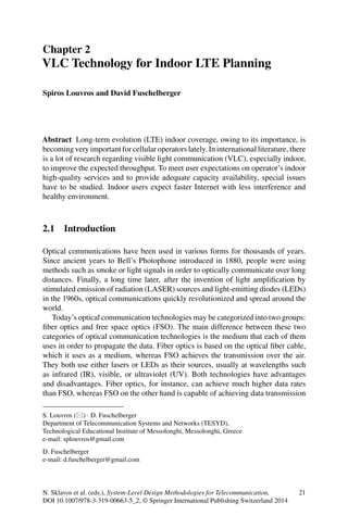
  • 5. 2 VLC Technology for Indoor LTE Planning 25 Fig. 2.1 Comparison among LTE and other existing optical wireless technologies thus restricting its high data rate applications to short-distance communication links [1]. However, by providing appropriate indoor illumination planning and number of LED lamps in the indoor design, range will always be sufficiently small to provide enough signal strength on receiver and NLOS will never be the case. Moreover, for sufficient ranges and after proper illumination design and multiple LED arrays in the building ceiling, data rate performance is comparable to all radio technologies since distance will be eliminated owing to LED array reuse factor. To test the performance of VLC technology in several ranges, a simple PHY layer VLC prototype has been implemented, as part of undergraduate student thesis, in the Telecom Laboratories of the Department of Telecommunication Systems and Networks of Technological Educational Institute of Messolonghi. This prototype was only a simple implementa- tion, meaning that it was not protected against visible light interference. Furthermore, neither preample electrical filter nor channel equalizer to fight back intersymbol in- terference (ISI) and multipath channel fadings was implemented. Under several test measurements, bit rates of 1 Mbps have been demonstrated [3]. Concluding about data rates and ranges, VLC, under appropriate illumination design and LED array distance reuse, provides superior performances over short-range radio technology competitors such as ZigBee and Bluetooth (Fig. 2.1). The raising issue of interference of background light sources could be easily eliminated by using appropriate optical filters, a well-known technique proposed in several applications, like OMEGA FP7 project [4]. Available bandwidth, interfer- ence, and security are other issues in which VLC is considered to be superior as it can provide both partial and full solutions to a number of wireless radio environment technological problems. Such solutions include the increasingly limited availability of conventional RF bandwidths for electronic equipment, the possible communi- cations interference with sensitive electrical equipment, and the door-to-door data security [1].
  • 6. 26 S. Louvros and D. Fuschelberger The perceived negative health consequences of existing radio technologies [1], as indicated in Fig. 2.5, when exposed to high RF and microwave levels—especially for health-sensitive human groups or buildings (schools, hospitals)—is a severe is- sue. From health perspective, all such applications and solutions might relax indoor space from radio emissions of contemporary telecommunication systems (WiFi, WiMax, Bluetooth, and UWB), which in certain cases are prohibitive (e.g., hospi- tals, airplanes, and areas inhabited by elderly people) or nondesirable (e.g., schools, university class rooms). Consequently, by replacing existing microwave-based and radio-based wireless networks, a next-generation green wireless communication net- work that will transform our everyday experiences and contribute to the idea of cyber green communication networks is obtained. Moreover, in addition to all previously mentioned metrics, there is also one major advantage of optical VLC technology compared to any radio competitor. This ad- vantage is the OFDM compatibility and superiority over VLC [5]. Indeed, OFDM enables very high data rate transmission with low computational complexity at the receiver since it is robust to multipath propagation. OFDM entirely eliminates the need for complex algorithms to cope with ISI, which typically gets worse with higher data rates. However, a standard OFDM transmitter produces a complex-valued sig- nal. Through a simple mathematical “trick,” this signal can be converted into a real-valued signal whose amplitude greatly varies in time. As a consequence, the peak-to-average-ratio (PAR) is high. This causes concerns in RF communications because of the detrimental impact on system performance due to power amplifier nonlinearities. For optical wireless communications, this effect, however, can be turned into an advantage as the high PAR signal can be exploited for intensity mod- ulation [6]. Given that the minimum illumination for reading purposes is 400 lx, and that this already translates into a signal-to-noise ratio (SNR) greater than 30 dB, OFDM combined with higher-order modulation techniques, such as M-level quadrature amplitude modulation (QAM), results in a powerful transmission tech- nology for incoherent visible light sources. D-Light team, University of Edinburgh, has demonstrated real-time data transmission using off-the-shelf LEDs of 130 Mbps. Finally, one last advantage ofVLC compared to any other available radio technology competitor is the interference issue. Using VLC over OFDM results in high link- level data rates, making VLC a very good candidate over OFDM for indoor LTE implementation. There is, however, one good question to be answered; what happens if multiple transmitters are deployed which together form an optical cellular network? In a recent publication [7], the area spectral efficiency (ASE) of future interference-limited wireless systems has been determined. The ASE is a measure of the maximum data rate per unit and per hertz bandwidth. It assumes a wireless network that is composed of multiple randomly deployed access points where each access point uses the same transmission resource/bandwidth. Basically, many access points means a high reuse of the same transmission resource and thus high data rate per unit area, but at a certain point this gain is outweighed by increased interference, which results in a drop in ASE. On the other hand, if there are only a few access points, this means a low resource reuse and, hence, low data rate per unit area, but also low interference.
  • 7. 2 VLC Technology for Indoor LTE Planning 27 Table 2.1 Advantages and disadvantages of VLC technology Advantages Disadvantages Harmless for the human body Atmospheric absorption Data transmission by sockets of existing light fixtures Shadowing/signal deterioration Alleviation of problems associated with radio frequency (RF) communication systems Beam dispersion Far less energy consumption Interference from background light sources Increased security Compact integration on sensors through small dimensions No communication if no “line of sight” Huge number of channels available without interfering with other sources Only discrete spectrum available as light source and sensor Simple electronics as drive for the LEDs Noise from interference of other sources has to be filtered No influence to other sensitive equipment through radio waves Therefore, there is an optimum point for the ASE. This optimum ASE for an indoor environment is found to be 4 × 10−4 bits/s/Hz/m2 . Implementing cellular networks and presumably LTE over VLC technology has, among other aforementioned advantages, the benefit of security and privacy. In- deed, using VLC technology, there will be no interference for indoor applications among rooms as rooms are typically separated by walls and light does not prop- agate through walls; an option, which does not hold in case of RF signals. If we assume a typical room of the size 4 m × 4 m = 16 m2 , and a VLC transmitter that is capable of delivering 130 Mbps with an off-the-shelf LED lamp of 20 MHz band- width, as demonstrated by the D-Light team, this would result inASE of: 130 × 106 [bits/s]/(20 × 106 [Hz] × 16 m2 ) = 0.41 bits/s/Hz/m2 . Comparing this result to the maximum 0.0004 bits/s/Hz/m2 for state-of-the-art wireless systems, we can observe a 1,025 times higher ASE. This essentially means thatVLC technology has the potential to provide wireless Gbps indoor services (over, of course, short ranges of 1–10 m) using standard off-the-shelf LEDs. This results in a massive RF spectrum relief, which frees up RF resources for the provision of better services in areas where VLC technology is difficult to use such as in remote areas. Taking this idea further and exploiting particular LED light radiation charac- teristics from different light sources in a room coexistence scenario, the expected ASE improvement could reach well beyond the factor of 2,000 and more. Concluding, VLC seems to be complementary and in some aspects superior to radio technologies. WiFi might be used for wide-area coverage within a building and ZigBee for short-range communications. However, interference, unlimited band- width, health issues, OFDM, and security support the VLC application and data rates could be in adequate level using many VLC LED arrays for short- to medium- range indoor communications. Table 2.1 presents the major pros and cons of the VLC technology.
  • 8. 28 S. Louvros and D. Fuschelberger 2.3.2 VLC: Innovation and Standards Although VLC concept has its origin back to year 1880 and Alexander Graham Bell [8], the first steps of a communication system using visible light while serving il- lumination requirements of indoor spaces were made at the end of last century [9]. Since then, several research groups have shown great interest in modeling, analyzing, and developing prototypes in order to assess the feasibility and the performance of a VLC system. In this context, the work of Nakagawa Laboratory of Keio University was pioneering and boosted the interest in VLC [10–14]. This work led to the es- tablishment of the VLCC Japan in 2003, which provided the first standards (JEITA CP-1221 and CP-1222) for VLC systems in 2007. The key component of VLC systems is an LED radiating visible light, which is properly modulated for transmission information, while retaining its illumination capability. White-light LEDs are the most promising ones from illumination and communication point of view. Most research work and experiments are based on phosphorescent white LED, which consists of a blue LED chip covered with a layer of yellow phosphor. These chips are of low cost and have simpler driving, but they present a low modulation bandwidth (2–3 MHz). Proper blue-filtering before the detector allows only blue component of white light, thus increasing the bandwidth to the order of 20 MHz [15, 16] with a total achievable bit rate of 100 Mbps using discrete multitone transmission (DMT). Channel equalization techniques have also been proposed [17, 18] for further bandwidth enhancement. A good achievement of 500 Mbps over a 5 m distance has been announced in 2010 from Heinrich Hertz Institute and Siemens [19]. Since 2010,VLC has been standardized by IEEE in the context ofWPAN (802.15) [20] for short-range wireless optical communication using visible light, including full MAC and PHY layer protocols. IEEE specifies three PHY layer modes: PHY I for outdoor usage, low data rate applications, on–off keying (OOK) with Manchester line coding and variable pulse position modulation (VPPM) with 4B6B line coding, data rates in the tens to hundreds of kbps, and RS outer coding; PHY II for indoor usage, moderate data rate applications, OOK with 8B10B line coding andVPPM with 4B6B line coding, data rates varying from 1.25 to 96 Mbps, and RS coding; PHY III for indoor high rate applications using color shift keying (CSK) with multiple light sources and detectors, supported data rates up to 96 Mbps, using RS coding. Important work has also been performed by the hOME GigabitAccess (OMEGA) project [4], funded by the European Union within FP7. The project ended by March 2011 with the development of a fullVLC prototype for video broadcasting and a gen- eral MAC protocol for home environments for IR, VLC, power line communications (PLC), and RF PHY layers interoperability. 2.4 LTE Implementation Over VLC: Technical Review Regarding the general concept of VLC, as already mentioned, a primary future vision of successful implementation and usage would be the combination of LED illumination along with data access. This is what makes VLC more promising with
  • 9. 2 VLC Technology for Indoor LTE Planning 29 Fig. 2.2 VLC indoor LTE coverage implementation proposal regard to its family FSO: the fact that the medium itself may be used for additional purposes in parallel. Figure 2.2 presents the LTE indoor coverage over LTE technology proposal. VLC advantages and standards have already been presented. In such an implementation, indoor planners could make use of several existing technologies for advanced ap- plications and purposes [21]. From outdoor cellular operator network to the indoor coverage glass, single-mode (SM) optical fibers should be used and appropriate capacity planning should be performed to provide appropriate bandwidth for opti- cal Ethernet transmission. Inside buildings, polymer optical fibers could be used as a cheaper solution for the optical signal distribution. Optical distributors/splitters should be provided to distribute optical signal throughout building floors and rooms. Finally, LEDs with appropriate driving circuit and optical to electrical converters should also be used as the indoor distribution and illumination system. 2.4.1 Glass Optical Fiber According to standards, LTE ideally needs Ethernet links over fiber optics. Opti- cal fiber planning includes several stages. A wide variety of specifications shall be used at an early stage. Regarding the physical medium, system topology should be considered including cable location and/or cable routes. Existing cable protection should be carefully examined (none, building ducts, or underground ducts). Cable specifications should follow standards (fiber, moisture ingression) and number of fibers per cable shall be considered and defined. Regarding network issues, network applications and proposed topology shall be finalized together with transmission standards (SDH, SONET), available Ethernet bit rates, coding, and multiplexing.
  • 10. 30 S. Louvros and D. Fuschelberger Fig. 2.3 Power budget calculation including margins and losses Specifically for the fiber itself, several parameters and characteristics have to be de- cided. First of all, it has to be decided whether multimode (MM) or SM shall be used, also the core size and fiber numerical aperture (NA), appropriate fiber attenuation for the link have to be determined, and budget calculations have to be done. Also, based on Ethernet-supported bit rate, fiber dispersion, including all tolerances, shall be considered. Mostly, on metropolitan networks, connectors and splitters are used quite often. For this reason, considerations on connector types, connector losses and reflections, available tolerances, mechanical or fusion splices, loss and tolerances and termination enclosures, and patch panel losses have to be calculated on link budget. When planning is performed, always the worst case is considered, calculating also tolerances. As an example, assume the worst case transmitter output power is − 12 dBm and the worst case receiver input power needed is − 30 dBm. Then, power budget = − 12 dBm − (− 30 dBm) = 18 dB of attenuation is possible over the link before failure (nonavailability) occurs. To find maximum available fiber attenuation, we substitute from available 18 dB budget the expected loss due to connectors (con- nector attenuations 1 dB per connector) and splices (splice attenuation 1.5 dB per splicing) and we are left with total allowed fiber attenuation of 12.8 dB. However, this is not always enough. Indeed, we shall also add expected margins due to fiber aging (the typical operating lifetime of a communication transmission system may be as high as 20–30 years), extra future splices, extra fiber length in future operator, and maintenance repairing and extra upgrades in the bit rate or advances in multiplexing. Figure 2.3 presents an example of power budget calculation including all losses and expected margins. In order to get a more sophisticated optical fiber planning, power penalties should be included in the analysis. Power penalty is indeed the initial calculated power increment in order to eliminate any undesired effects from expected system noise or system distortion. Most common penalties are calculated owing to fiber disper- sion effects and fiber attenuation. There are two dominant fiber dispersions, time