
Empfohlen
Weitere ähnliche Inhalte
Ähnlich wie ECE131_UNIT1_Part1.ppt
Ähnlich wie ECE131_UNIT1_Part1.ppt (20)
Kürzlich hochgeladen
Kürzlich hochgeladen (20)
ECE131_UNIT1_Part1.ppt
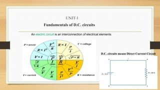
- 1. UNIT-1 Fundamentals of D.C. circuits An electric circuit is an interconnection of electrical elements D.C. circuits means Direct Current Circuit
- 2. Ohm’s Law Given by Georg Simon Ohm (1787–1854), a German physicist finding the relationship between current and voltage for a resistor. This relationship is known as Ohm’s law. • Statement: Ohm’s law states that the voltage v across a resistor is directly proportional to the current i flowing through the resistor. • Mathematically, This is the mathematical form of Ohm’s law
- 3. • R is measured in the unit of ohms • V is the Potential Difference between two ends of the conductor (in Volts) • I=Current flowing through the conductor (in Ampere) • The resistance R of an element denotes its ability to resist the flow of electric current; it is measured in ohms ( ) • 1 = 1 V/1A
- 5. Applications of Ohm’s Law • 1. To find unknown Voltage (V) • 2. To Find unknown Resistance (R) • 3. To Find unknown Current (I) • 4. Can be used to find Unknown Conductance (G)=1/R • 5. Can be used to find unknown Power (P)=VI • 6. Can be used to find unknown conductivity or Resistivity
- 6. For Example • Q.1 An electric iron draws 2 A at 120 V. Find its resistance. • Solution: • Q.2 The essential component of a toaster is an electrical element (a resistor) that converts electrical energy to heat energy. How much current is drawn by a toaster with resistance 15 ohm at 110 V? Solution: I=V/R=110/15=7.333A
- 7. Some other Problems on Ohm’s Law • Q.3 In the circuit shown in Fig., calculate the current i, the conductance G, and the power p. • Solution:
- 8. Q.4 For the circuit shown in Fig., calculate the voltage v, the conductance G, and the power p. • Solution: • Q.5 A voltage source of is connected across a 5-k resistor. Find the current through the resistor and the power dissipated. • Solution:
- 10. DISADVANTAGES • Ohm’s law by itself is not sufficient to analyze circuits. • Unable to solve typical Numerical problems
- 11. Nodes, Branches, and Loops • BRANCH: A branch represents a single element such as a voltage source or a resistor. • NODE: A node is the point of connection between two or more branches. • LOOP: A loop is any closed path in a circuit. A network with b branches, n nodes, and l independent loops will satisfy the fundamental theorem of network topology:
- 12. Kirchhoff’s Laws • First introduced in 1847 by the German physicist Gustav Robert Kirchhoff
- 13. Kirchhoff’s Current Law (KCL) • Kirchhoff’s current law (KCL) states that the algebraic sum of currents entering a node (or a closed boundary) is zero. Mathematically, KCL implies that
- 14. Sign Convention for KCL: Entering Current: Taken as +ve Leaving Current: Taken as -ve The sum of the currents entering a node is equal to the sum of the currents leaving the node.
- 15. Example for KCL
- 16. Kirchhoff’s Voltage Law (KVL) • Kirchhoff’s voltage law (KVL) states that the algebraic sum of all voltages around a closed path (or loop) is zero. • mathematically, KVL states that
- 17. Sign Convention for KVL • KVL can be applied in two ways: • 1. By taking either a clockwise or a counterclockwise trip around the loop. • 2. By the algebraic sum of voltages around the loop is zero.
- 18. Sign Convention of KVL for R, L and C
- 20. Example-2 for KVL Sum of voltage rises=Sum of voltage drops Equivalent Circuit
- 21. Example-3 for KVL For the circuit in Fig.1(a), find voltages v1 and v2.
- 23. Example-5 for Ohm’s Law and KVL
- 24. Practice Problem for KCL and KVL
- 28. Note: This rule can be generalized for any number of resistors in series
- 30. Example for Voltage Division Rule
- 32. Numerical Problem for Current Division Rule
- 33. Example-2 for Current Division Rule
- 35. SERIES CONNECTIONS • SERIES CONNECTION: Two or more elements are in series if they exclusively share a single node and consequently carry the same current.
- 36. Point to Remember for Series Circuits
- 37. PARELLEL CONNECTION • PARALLEL CONNECTION: Two or more elements are in parallel if they are connected to the same two nodes and consequently have the same voltage across them
- 38. BATTERY VOLTAGE IN SERIES AND PARALLEL
- 40. Note: Resistors in series behave as a single resistor whose resistance is equal to the sum of the resistances of the individual resistors.
- 41. Resistors in Parallel The equivalent resistance of two parallel resistors is equal to the product of their resistances divided by their sum.
- 42. How to find Equivalent Resistance for Series-Parallel Combinations
- 43. Example: To find Req
- 44. Practice Problem to find Equivalent Resistance
- 45. SOURCES OF ELECTRICAL ENERGY • A Source is a device which converts mechanical, chemical, thermal or some other form of energy into electrical energy. In other words, the source is an active network element meant for generating electrical energy. • The various types of sources available in the electrical network are voltage source and current sources. • Voltage Source and Current Source • A voltage source has a forcing function of emf, whereas the current source has a forcing function of current.
- 49. Ideal and non ideal (Practical) energy sources
- 51. Independent Dependent Voltage and Current Source • The source which supplies the active power to the network is known as the electrical source. • The electrical source is of two types namely independent source and dependent source. • The Independent and Dependent source means, whether the voltage or current sources are either depending upon some other source, or they are acting independently.
- 52. Independent and Dependent Sources Independent Voltage and Current Source • Independent sources are that which does not depend on any other quantity in the circuit. They are two terminal devices and has a constant value, i.e. the voltage across the two terminals remains constant irrespective of all circuit conditions. • The strength of voltage or current is not changed by any variation in the connected network the source is said to be either independent voltage or independent current source. In this, the value of voltage or current is fixed and is not adjustable Dependent Voltage and Current Source • The sources whose output voltage or current is not fixed but depends on the voltage or current in another part of the circuit is called Dependent or Controlled source. They are four terminal devices. When the strength of voltage or current changes in the source for any change in the connected network, they are called dependent sources. The dependent sources are represented by a diamond shape.
- 53. DEPENDENT OR CONTROLLED SOURCES
- 55. IDEAL AND PRACTICAL VOLTAGE SOURCE
- 58. Voltage Controlled Voltage Source (VCVS) • In voltage controlled voltage source the voltage source is dependent on any element of the circuit.
- 62. SOURCE TRANSFORMATION A source transformation is the process of replacing a voltage source V in series with a resistor R by a current source is in parallel with a resistor R, or vice versa.
- 64. SOURCE TRANSFORMATION FOR INDEPENDENT SOURCES SOURCE TRANSFORMATION FOR DEPENDENT SOURCES Note: Source transformation also applies to dependent sources, provided, we need to carefully handle the dependent variable
- 66. Example for Source Transformation
- 69. Example: Delta to Star
- 70. Example: Star to Delta
- 72. Nodal Analysis or Nodal Method • Nodal analysis provides a general procedure for analyzing circuits using node voltages as the circuit variables. • Choosing node voltages instead of element voltages as circuit variables is convenient and reduces the number of equations one must solve simultaneously. • Applicable to Nodes only. • It is used to find the unknown node voltages. • This Method is Application of KCL+Ohm’s Law Only
- 73. Steps to Determine Node Voltages • 1. Select one nodes out of ‘n’ node as the reference node. Assign voltages to the remaining nodes. The voltages are referenced with respect to the reference node. • 2. Apply KCL to each of the non-reference nodes. Use Ohm’s law to express the branch currents in terms of node voltages. • 3. Solve the resulting simultaneous equations to obtain the unknown node voltages.
- 74. • selecting a node as the reference or datum node. The reference node is commonly called as ground. • The number of non-reference nodes is equal to the number of independent equations that we have to derive. Current flows from a higher potential to a lower potential in a resistor.
- 75. Example for Nodal Analysis Solving these two equations, you can find unknown node voltages
- 76. Practice Problem for Nodal Analysis