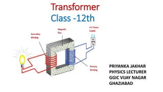
SlideShare ist ein Scribd-Unternehmen logo
1 von 14
Transformer
Class -12th
PRIYANKA JAKHAR
PHYSICS LECTURER
GGIC VIJAY NAGAR
GHAZIABAD
Transformer:
Transformer is a device which converts lower
alternating voltage at higher current into higher
alternating voltage at lower current.
S Load
P
•Transformer does not operate on direct current. It
operates only on alternating voltages at input as
well as at output.
•Transformer does not amplify power as vacuum
tube.
•Transformer, a device based on mutual induction
converts magnetic energy into electrical energy.
The transformer is a device used for converting a low alternating voltage to a high alternating
voltage or vice-versa.
A Transformer based on the Principle of mutual induction according to this principle, the
amount of magnetic flux linked with a coil changing, an e.m.f is induced in the neighboring
coil.
A transformer is an electrical device which is used for changing the A.C. voltages. A
transformer is most widely used device in both low and high current circuit. As such
transformers are built in an amazing strength of sizes. In electronic, measurement and control
circuits, transformer size may be so small that it weight only a few tens of grams where as in
high voltage power circuits, it may weight hundred of tones.
In a transformer, the electrical energy transfer from one circuit to another circuit takes place
without the use of moving parts.
Transformer is, therefore, an essential piece of apparatus both for high and low current
circuits.
APPARATUS REQUIRED
IRON ROD
COPPER WIRE
VOLTMETRE
AMMETRE
WORKING PRINCIPLE
The transformer works in the principle of mutual induction .
“The principle of mutual induction states that when the two coils are inductively coupled
and if the current in coil change uniformly then the e.m.f. induced in the other coils. This e.m.f
can drive a current when a closed path is provide to it.”
When the alternating current flows in the primary coils, a changing magnetic flux is generated
around the primary coil.
The changing magnetic flux is transferred to the secondary coil through the iron core .
The changing magnetic flux is cut by the secondary coil, hence induces an e.m.f in the
secondary coil.
Now if load is connected to a secondary winding, this e.m.f drives a current through it .
The magnitude of the output voltage can be controlled by the ratio of the no. of primary coil
and secondary coil .
The frequency of mutually induced e.m.f as same that of the alternating source which
supplying to the primary winding .
STRUCTURE OF TRANSFORMER
# The transformer two inductive coils ,these are electrical separated but linked
through a common magnetic current circuit .
# These two coils have a high mutual induction.
# One of the two coils is connected of alternating voltage .this coil in which
electrical energy is fed with the help of source called primary winding (P) .
# The other winding is connected to a load the electrical energy is transformed to
this winding drawn out to the load .this winding is called secondary winding(S) .
# The primary and secondary coil wound on a ferromagnetic metal core .
# The function of the core is to transfer the changing magnetic flux from the
primary coil to the secondary coil .
# The primary has N1 no of turns and the secondary has N2 no of turns the of
turns plays major important role in the function of transformer.
EP = - NP dΦ / dt ES = - NS dΦ / dt
ES / EP = NS / NP = K
(where K is called Transformation Ratio or Turns Ratio)
For an ideal transformer,
Output Power = Input Power
ESIS = EPIP
ES / EP = IP / IS
ES / EP = IP / IS = NS / NP
Efficiency (η):
η = ESIS /EPIP
For an ideal transformer η is 100%
Type of transformer
Step - up Transformer Step-down transformer
Transformer
It is a device which can change a low voltage of high current into a high voltage
of low current and vice-versa.
Its working is based on mutual induction.
There is no electrical contact between them .
The desire change in voltage or current without any change in frequency.
There are two types of transformers.
(i) Step-up Transformers It converts a low voltage of high current into a high
current.
A transformer which increases the voltages is called a step- up transformer.
Step - up Transformer:
Load
P
S NS > NP i.e. K > 1
ES > EP & IS < IP
(ii) Step-down Transformer It converts a high voltage of low current into a low voltage of high
current. Step - down
Transformer:
P S
Load
NS < NP i.e. K < 1
ES < EP & IS > IP
Energy Losses in a Transformer:
1. Copper Loss: Heat is produced due to the resistance of the copper windings of Primary and
Secondary coils when current flows through them.
This can be avoided by using thick wires for winding.
2. Flux Loss: In actual transformer coupling between Primary and Secondary coil is not perfect.
So, a certain amount of magnetic flux is wasted.
Linking can be maximised by winding the coils over one another.
3. Iron Losses:
a)Eddy Currents Losses:
When a changing magnetic flux is linked with the iron core, eddy currents are set up which in turn
produce heat and energy is wasted.
Eddy currents are reduced by using laminated core instead of a solid iron block because in
laminated core the eddy currents are confined with in the lamination and they do not get added
up to produce larger current.
In other words their paths are broken instead of continuous ones.
Solid Core
Laminated Core
b) Hysteresis Loss:
When alternating current is passed, the iron core is magnetised and demagnetised repeatedly
over the cycles and some energy is being lost in the process.
This can be minimised by using suitable material with thin hysteresis loop.
4. Losses due to vibration of core: Some electrical energy is lost in the form of mechanical
energy due to vibration of the core and humming noise due to magnetostriction effect.
USES OF TRANSFORMERS
1. In voltage regulator for T.V., refrigerator, computer, air conditioner, etc.
2. A step down transformer is used for welding purposes.
3. A step down transformer is used for obtaining large current.
4. A step up transformer is used for the production of X- Rays and NEON advertisement.
5. Transformers are used in voltage regulators and stabilized power supplies.
6. Transformers are used in the transmissions of a.c. over long distances.
7. Small transformers are used in Radio sets, telephones, loud speakers and electric bells etc
IDEAL V/S PRACTICAL TRANSFORMER
A transformer is said to be ideal if it satisfies the following properties, but no
transformer is ideal in practice.
It has no losses .
Windings resistance are zero .
There is no flux leakage .
Small current is required to produce the magnetic field While the practical
transformer has windings resistance , some leakage flux and has lit bit losses .

Weitere ähnliche Inhalte

Was ist angesagt?

Semiconductor Devices Class 12 Part-2
Semiconductor Devices Class 12 Part-2Semiconductor Devices Class 12 Part-2
Semiconductor Devices Class 12 Part-2
Self-employed
 
L11 magnetic circuits
L11   magnetic circuitsL11   magnetic circuits
L11 magnetic circuits
Satyakam
 
Current Electricity Class 12 Part-2
Current Electricity Class 12 Part-2Current Electricity Class 12 Part-2
Current Electricity Class 12 Part-2
Self-employed
 
Alternating Currents Class 12
Alternating Currents Class 12Alternating Currents Class 12
Alternating Currents Class 12
Self-employed
 
Current Electricity Class 12 Part-1
Current Electricity Class 12 Part-1Current Electricity Class 12 Part-1
Current Electricity Class 12 Part-1
Self-employed
 

Was ist angesagt? (20)

physics investigatory on Electromagnetic induction
physics investigatory on Electromagnetic inductionphysics investigatory on Electromagnetic induction
physics investigatory on Electromagnetic induction
 
Physics project abhishek
Physics project abhishekPhysics project abhishek
Physics project abhishek
 
Mutual induction
Mutual inductionMutual induction
Mutual induction
 
Magnetic field lines
Magnetic field linesMagnetic field lines
Magnetic field lines
 
electromagnetic induction
electromagnetic inductionelectromagnetic induction
electromagnetic induction
 
Semiconductor Devices Class 12 Part-2
Semiconductor Devices Class 12 Part-2Semiconductor Devices Class 12 Part-2
Semiconductor Devices Class 12 Part-2
 
Sanjay
SanjaySanjay
Sanjay
 
Inductance
InductanceInductance
Inductance
 
Physics project class 12
Physics project class 12Physics project class 12
Physics project class 12
 
Hall Effect
Hall EffectHall Effect
Hall Effect
 
L11 magnetic circuits
L11   magnetic circuitsL11   magnetic circuits
L11 magnetic circuits
 
XII INVESTIGATORY PHYSICS PROJECT
XII INVESTIGATORY PHYSICS PROJECTXII INVESTIGATORY PHYSICS PROJECT
XII INVESTIGATORY PHYSICS PROJECT
 
self inductance
self inductanceself inductance
self inductance
 
Current Electricity Class 12 Part-2
Current Electricity Class 12 Part-2Current Electricity Class 12 Part-2
Current Electricity Class 12 Part-2
 
Physics Project for class 12 isc Junction and diode
Physics Project for class 12 isc Junction and diodePhysics Project for class 12 isc Junction and diode
Physics Project for class 12 isc Junction and diode
 
Alternating Currents Class 12
Alternating Currents Class 12Alternating Currents Class 12
Alternating Currents Class 12
 
Alternating Current
Alternating CurrentAlternating Current
Alternating Current
 
Electromagnetic induction
Electromagnetic induction Electromagnetic induction
Electromagnetic induction
 
Physics investigatory project
Physics investigatory projectPhysics investigatory project
Physics investigatory project
 
Current Electricity Class 12 Part-1
Current Electricity Class 12 Part-1Current Electricity Class 12 Part-1
Current Electricity Class 12 Part-1
 

Ähnlich wie Transformer

kupdf.net_physics-project-on-quottransformersquot - Copy.pdf
kupdf.net_physics-project-on-quottransformersquot - Copy.pdfkupdf.net_physics-project-on-quottransformersquot - Copy.pdf
kupdf.net_physics-project-on-quottransformersquot - Copy.pdf
PatelRushabh9
 
rushabh project physics 1.docx
rushabh project physics 1.docxrushabh project physics 1.docx
rushabh project physics 1.docx
PatelRushabh9
 
transformers electronic notes pptx in depth
transformers electronic notes pptx in depthtransformers electronic notes pptx in depth
transformers electronic notes pptx in depth
Anderson939966
 
TRANSFORMER WORKING MANUFACTURINIG
 TRANSFORMER WORKING MANUFACTURINIG TRANSFORMER WORKING MANUFACTURINIG
TRANSFORMER WORKING MANUFACTURINIG
Sumit Saini
 
Physics investigatory project
Physics investigatory projectPhysics investigatory project
Physics investigatory project
Mahima Kriplani
 

Ähnlich wie Transformer (20)

Transformer
TransformerTransformer
Transformer
 
Transformer
TransformerTransformer
Transformer
 
Full transformer
Full transformerFull transformer
Full transformer
 
Transformer construction,types and working
Transformer construction,types and workingTransformer construction,types and working
Transformer construction,types and working
 
Step-down transformer Physics project Class 12 CBSE Final
Step-down transformer Physics project Class 12 CBSE FinalStep-down transformer Physics project Class 12 CBSE Final
Step-down transformer Physics project Class 12 CBSE Final
 
Transformer
TransformerTransformer
Transformer
 
Tansformer @dheeraj upadhyay
Tansformer @dheeraj upadhyayTansformer @dheeraj upadhyay
Tansformer @dheeraj upadhyay
 
Transformer by Hemant
Transformer by HemantTransformer by Hemant
Transformer by Hemant
 
Transformer
TransformerTransformer
Transformer
 
Transformers
TransformersTransformers
Transformers
 
transformer slide prsentation
transformer slide prsentation transformer slide prsentation
transformer slide prsentation
 
kupdf.net_physics-project-on-quottransformersquot - Copy.pdf
kupdf.net_physics-project-on-quottransformersquot - Copy.pdfkupdf.net_physics-project-on-quottransformersquot - Copy.pdf
kupdf.net_physics-project-on-quottransformersquot - Copy.pdf
 
rushabh project physics 1.docx
rushabh project physics 1.docxrushabh project physics 1.docx
rushabh project physics 1.docx
 
Transformer.pptx
Transformer.pptxTransformer.pptx
Transformer.pptx
 
Transformer
TransformerTransformer
Transformer
 
Transformer
TransformerTransformer
Transformer
 
transformers electronic notes pptx in depth
transformers electronic notes pptx in depthtransformers electronic notes pptx in depth
transformers electronic notes pptx in depth
 
Transfomer
TransfomerTransfomer
Transfomer
 
TRANSFORMER WORKING MANUFACTURINIG
 TRANSFORMER WORKING MANUFACTURINIG TRANSFORMER WORKING MANUFACTURINIG
TRANSFORMER WORKING MANUFACTURINIG
 
Physics investigatory project
Physics investigatory projectPhysics investigatory project
Physics investigatory project
 

Mehr von Priyanka Jakhar

Mehr von Priyanka Jakhar (20)

PHYSICAL WORLD part 2
PHYSICAL WORLD part 2PHYSICAL WORLD part 2
PHYSICAL WORLD part 2
 
Capacitor
Capacitor Capacitor
Capacitor
 
Physical world part 1
Physical world part 1Physical world part 1
Physical world part 1
 
PHYSICAL WORLD part 1
PHYSICAL WORLD part 1PHYSICAL WORLD part 1
PHYSICAL WORLD part 1
 
Mutual induction
Mutual induction    Mutual induction
Mutual induction
 
Eddy current
Eddy currentEddy current
Eddy current
 
Ultasonic sensor
Ultasonic sensorUltasonic sensor
Ultasonic sensor
 
electromagnetic induction ( part 1 )
electromagnetic induction ( part 1 )electromagnetic induction ( part 1 )
electromagnetic induction ( part 1 )
 
Breadboard
BreadboardBreadboard
Breadboard
 
Jumper wires
Jumper wiresJumper wires
Jumper wires
 
Earths magnetism part 1
Earths magnetism part 1Earths magnetism part 1
Earths magnetism part 1
 
Earths magnetism
Earths magnetismEarths magnetism
Earths magnetism
 
Superconductor
SuperconductorSuperconductor
Superconductor
 
VandE GRAFF generator
VandE GRAFF generatorVandE GRAFF generator
VandE GRAFF generator
 
Class 12 th semiconductor part 4
Class 12 th semiconductor part 4Class 12 th semiconductor part 4
Class 12 th semiconductor part 4
 
Class 12 th semiconductor part 3
Class 12 th semiconductor part 3Class 12 th semiconductor part 3
Class 12 th semiconductor part 3
 
Class 12 th semiconductor part 2
Class 12 th semiconductor part 2Class 12 th semiconductor part 2
Class 12 th semiconductor part 2
 
Class 12 th semiconductor part 1
Class 12 th semiconductor part 1Class 12 th semiconductor part 1
Class 12 th semiconductor part 1
 
Class 12 th semiconductor part 1
Class 12 th semiconductor part 1Class 12 th semiconductor part 1
Class 12 th semiconductor part 1
 
1 Conversion of Galvanometer into Ammeter and Voltmeter 2 Differences between...
1 Conversion of Galvanometer into Ammeter and Voltmeter 2 Differences between...1 Conversion of Galvanometer into Ammeter and Voltmeter 2 Differences between...
1 Conversion of Galvanometer into Ammeter and Voltmeter 2 Differences between...
 

Kürzlich hochgeladen

Russian Escort Service in Delhi 11k Hotel Foreigner Russian Call Girls in Delhi
Russian Escort Service in Delhi 11k Hotel Foreigner Russian Call Girls in DelhiRussian Escort Service in Delhi 11k Hotel Foreigner Russian Call Girls in Delhi
Russian Escort Service in Delhi 11k Hotel Foreigner Russian Call Girls in Delhi
kauryashika82
 
Gardella_Mateo_IntellectualProperty.pdf.
Gardella_Mateo_IntellectualProperty.pdf.Gardella_Mateo_IntellectualProperty.pdf.
Gardella_Mateo_IntellectualProperty.pdf.
MateoGardella
 
Making and Justifying Mathematical Decisions.pdf
Making and Justifying Mathematical Decisions.pdfMaking and Justifying Mathematical Decisions.pdf
Making and Justifying Mathematical Decisions.pdf
Chris Hunter
 
Beyond the EU: DORA and NIS 2 Directive's Global Impact
Beyond the EU: DORA and NIS 2 Directive's Global ImpactBeyond the EU: DORA and NIS 2 Directive's Global Impact
Beyond the EU: DORA and NIS 2 Directive's Global Impact
PECB
 

Kürzlich hochgeladen (20)

Mattingly "AI & Prompt Design: The Basics of Prompt Design"
Mattingly "AI & Prompt Design: The Basics of Prompt Design"Mattingly "AI & Prompt Design: The Basics of Prompt Design"
Mattingly "AI & Prompt Design: The Basics of Prompt Design"
 
Unit-IV- Pharma. Marketing Channels.pptx
Unit-IV- Pharma. Marketing Channels.pptxUnit-IV- Pharma. Marketing Channels.pptx
Unit-IV- Pharma. Marketing Channels.pptx
 
Paris 2024 Olympic Geographies - an activity
Paris 2024 Olympic Geographies - an activityParis 2024 Olympic Geographies - an activity
Paris 2024 Olympic Geographies - an activity
 
Russian Escort Service in Delhi 11k Hotel Foreigner Russian Call Girls in Delhi
Russian Escort Service in Delhi 11k Hotel Foreigner Russian Call Girls in DelhiRussian Escort Service in Delhi 11k Hotel Foreigner Russian Call Girls in Delhi
Russian Escort Service in Delhi 11k Hotel Foreigner Russian Call Girls in Delhi
 
Gardella_Mateo_IntellectualProperty.pdf.
Gardella_Mateo_IntellectualProperty.pdf.Gardella_Mateo_IntellectualProperty.pdf.
Gardella_Mateo_IntellectualProperty.pdf.
 
microwave assisted reaction. General introduction
microwave assisted reaction. General introductionmicrowave assisted reaction. General introduction
microwave assisted reaction. General introduction
 
Class 11th Physics NEET formula sheet pdf
Class 11th Physics NEET formula sheet pdfClass 11th Physics NEET formula sheet pdf
Class 11th Physics NEET formula sheet pdf
 
Unit-V; Pricing (Pharma Marketing Management).pptx
Unit-V; Pricing (Pharma Marketing Management).pptxUnit-V; Pricing (Pharma Marketing Management).pptx
Unit-V; Pricing (Pharma Marketing Management).pptx
 
APM Welcome, APM North West Network Conference, Synergies Across Sectors
APM Welcome, APM North West Network Conference, Synergies Across SectorsAPM Welcome, APM North West Network Conference, Synergies Across Sectors
APM Welcome, APM North West Network Conference, Synergies Across Sectors
 
Presentation by Andreas Schleicher Tackling the School Absenteeism Crisis 30 ...
Presentation by Andreas Schleicher Tackling the School Absenteeism Crisis 30 ...Presentation by Andreas Schleicher Tackling the School Absenteeism Crisis 30 ...
Presentation by Andreas Schleicher Tackling the School Absenteeism Crisis 30 ...
 
Making and Justifying Mathematical Decisions.pdf
Making and Justifying Mathematical Decisions.pdfMaking and Justifying Mathematical Decisions.pdf
Making and Justifying Mathematical Decisions.pdf
 
Nutritional Needs Presentation - HLTH 104
Nutritional Needs Presentation - HLTH 104Nutritional Needs Presentation - HLTH 104
Nutritional Needs Presentation - HLTH 104
 
Holdier Curriculum Vitae (April 2024).pdf
Holdier Curriculum Vitae (April 2024).pdfHoldier Curriculum Vitae (April 2024).pdf
Holdier Curriculum Vitae (April 2024).pdf
 
Mattingly "AI & Prompt Design: Structured Data, Assistants, & RAG"
Mattingly "AI & Prompt Design: Structured Data, Assistants, & RAG"Mattingly "AI & Prompt Design: Structured Data, Assistants, & RAG"
Mattingly "AI & Prompt Design: Structured Data, Assistants, & RAG"
 
ICT Role in 21st Century Education & its Challenges.pptx
ICT Role in 21st Century Education & its Challenges.pptxICT Role in 21st Century Education & its Challenges.pptx
ICT Role in 21st Century Education & its Challenges.pptx
 
SECOND SEMESTER TOPIC COVERAGE SY 2023-2024 Trends, Networks, and Critical Th...
SECOND SEMESTER TOPIC COVERAGE SY 2023-2024 Trends, Networks, and Critical Th...SECOND SEMESTER TOPIC COVERAGE SY 2023-2024 Trends, Networks, and Critical Th...
SECOND SEMESTER TOPIC COVERAGE SY 2023-2024 Trends, Networks, and Critical Th...
 
SOCIAL AND HISTORICAL CONTEXT - LFTVD.pptx
SOCIAL AND HISTORICAL CONTEXT - LFTVD.pptxSOCIAL AND HISTORICAL CONTEXT - LFTVD.pptx
SOCIAL AND HISTORICAL CONTEXT - LFTVD.pptx
 
Advanced Views - Calendar View in Odoo 17
Advanced Views - Calendar View in Odoo 17Advanced Views - Calendar View in Odoo 17
Advanced Views - Calendar View in Odoo 17
 
Unit-IV; Professional Sales Representative (PSR).pptx
Unit-IV; Professional Sales Representative (PSR).pptxUnit-IV; Professional Sales Representative (PSR).pptx
Unit-IV; Professional Sales Representative (PSR).pptx
 
Beyond the EU: DORA and NIS 2 Directive's Global Impact
Beyond the EU: DORA and NIS 2 Directive's Global ImpactBeyond the EU: DORA and NIS 2 Directive's Global Impact
Beyond the EU: DORA and NIS 2 Directive's Global Impact
 

Transformer

  • 1. Transformer Class -12th PRIYANKA JAKHAR PHYSICS LECTURER GGIC VIJAY NAGAR GHAZIABAD
  • 2. Transformer: Transformer is a device which converts lower alternating voltage at higher current into higher alternating voltage at lower current. S Load P •Transformer does not operate on direct current. It operates only on alternating voltages at input as well as at output. •Transformer does not amplify power as vacuum tube. •Transformer, a device based on mutual induction converts magnetic energy into electrical energy.
  • 3. The transformer is a device used for converting a low alternating voltage to a high alternating voltage or vice-versa. A Transformer based on the Principle of mutual induction according to this principle, the amount of magnetic flux linked with a coil changing, an e.m.f is induced in the neighboring coil. A transformer is an electrical device which is used for changing the A.C. voltages. A transformer is most widely used device in both low and high current circuit. As such transformers are built in an amazing strength of sizes. In electronic, measurement and control circuits, transformer size may be so small that it weight only a few tens of grams where as in high voltage power circuits, it may weight hundred of tones. In a transformer, the electrical energy transfer from one circuit to another circuit takes place without the use of moving parts. Transformer is, therefore, an essential piece of apparatus both for high and low current circuits.
  • 4. APPARATUS REQUIRED IRON ROD COPPER WIRE VOLTMETRE AMMETRE
  • 5. WORKING PRINCIPLE The transformer works in the principle of mutual induction . “The principle of mutual induction states that when the two coils are inductively coupled and if the current in coil change uniformly then the e.m.f. induced in the other coils. This e.m.f can drive a current when a closed path is provide to it.” When the alternating current flows in the primary coils, a changing magnetic flux is generated around the primary coil. The changing magnetic flux is transferred to the secondary coil through the iron core . The changing magnetic flux is cut by the secondary coil, hence induces an e.m.f in the secondary coil. Now if load is connected to a secondary winding, this e.m.f drives a current through it . The magnitude of the output voltage can be controlled by the ratio of the no. of primary coil and secondary coil . The frequency of mutually induced e.m.f as same that of the alternating source which supplying to the primary winding .
  • 6. STRUCTURE OF TRANSFORMER # The transformer two inductive coils ,these are electrical separated but linked through a common magnetic current circuit . # These two coils have a high mutual induction. # One of the two coils is connected of alternating voltage .this coil in which electrical energy is fed with the help of source called primary winding (P) . # The other winding is connected to a load the electrical energy is transformed to this winding drawn out to the load .this winding is called secondary winding(S) . # The primary and secondary coil wound on a ferromagnetic metal core . # The function of the core is to transfer the changing magnetic flux from the primary coil to the secondary coil . # The primary has N1 no of turns and the secondary has N2 no of turns the of turns plays major important role in the function of transformer.
  • 7. EP = - NP dΦ / dt ES = - NS dΦ / dt ES / EP = NS / NP = K (where K is called Transformation Ratio or Turns Ratio) For an ideal transformer, Output Power = Input Power ESIS = EPIP ES / EP = IP / IS ES / EP = IP / IS = NS / NP Efficiency (η): η = ESIS /EPIP For an ideal transformer η is 100%
  • 8. Type of transformer Step - up Transformer Step-down transformer Transformer It is a device which can change a low voltage of high current into a high voltage of low current and vice-versa. Its working is based on mutual induction. There is no electrical contact between them . The desire change in voltage or current without any change in frequency.
  • 9. There are two types of transformers. (i) Step-up Transformers It converts a low voltage of high current into a high current. A transformer which increases the voltages is called a step- up transformer. Step - up Transformer: Load P S NS > NP i.e. K > 1 ES > EP & IS < IP
  • 10. (ii) Step-down Transformer It converts a high voltage of low current into a low voltage of high current. Step - down Transformer: P S Load NS < NP i.e. K < 1 ES < EP & IS > IP
  • 11. Energy Losses in a Transformer: 1. Copper Loss: Heat is produced due to the resistance of the copper windings of Primary and Secondary coils when current flows through them. This can be avoided by using thick wires for winding. 2. Flux Loss: In actual transformer coupling between Primary and Secondary coil is not perfect. So, a certain amount of magnetic flux is wasted. Linking can be maximised by winding the coils over one another. 3. Iron Losses: a)Eddy Currents Losses: When a changing magnetic flux is linked with the iron core, eddy currents are set up which in turn produce heat and energy is wasted. Eddy currents are reduced by using laminated core instead of a solid iron block because in laminated core the eddy currents are confined with in the lamination and they do not get added up to produce larger current. In other words their paths are broken instead of continuous ones.
  • 12. Solid Core Laminated Core b) Hysteresis Loss: When alternating current is passed, the iron core is magnetised and demagnetised repeatedly over the cycles and some energy is being lost in the process. This can be minimised by using suitable material with thin hysteresis loop. 4. Losses due to vibration of core: Some electrical energy is lost in the form of mechanical energy due to vibration of the core and humming noise due to magnetostriction effect.
  • 13. USES OF TRANSFORMERS 1. In voltage regulator for T.V., refrigerator, computer, air conditioner, etc. 2. A step down transformer is used for welding purposes. 3. A step down transformer is used for obtaining large current. 4. A step up transformer is used for the production of X- Rays and NEON advertisement. 5. Transformers are used in voltage regulators and stabilized power supplies. 6. Transformers are used in the transmissions of a.c. over long distances. 7. Small transformers are used in Radio sets, telephones, loud speakers and electric bells etc
  • 14. IDEAL V/S PRACTICAL TRANSFORMER A transformer is said to be ideal if it satisfies the following properties, but no transformer is ideal in practice. It has no losses . Windings resistance are zero . There is no flux leakage . Small current is required to produce the magnetic field While the practical transformer has windings resistance , some leakage flux and has lit bit losses .