
Empfohlen
Weitere ähnliche Inhalte
Was ist angesagt?
Was ist angesagt? (20)
Ähnlich wie Carbon Nanotube
Ähnlich wie Carbon Nanotube (20)
Mehr von Shahriar Shovon
Mehr von Shahriar Shovon (20)
Kürzlich hochgeladen
Kürzlich hochgeladen (20)
Carbon Nanotube
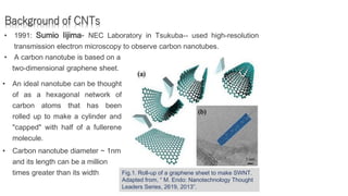
- 1. Background of CNTs • 1991: Sumio Iijima- NEC Laboratory in Tsukuba-- used high-resolution transmission electron microscopy to observe carbon nanotubes. • A carbon nanotube is based on a two-dimensional graphene sheet. • An ideal nanotube can be thought of as a hexagonal network of carbon atoms that has been rolled up to make a cylinder and "capped" with half of a fullerene molecule. • Carbon nanotube diameter ~ 1nm and its length can be a million times greater than its width Fig.1. Roll-up of a graphene sheet to make SWNT. Adapted from, “ M. Endo: Nanotechnology Thought Leaders Series, 2619, 2013”.
- 2. Structure of CNTs • Nanotubes can be single-walled (d = 1-2 nm), or multi-walled (d = 5- 80 nm) or double walled. • Multi-walled carbon nanotubes consists of several different single-walled carbon nanotubes concentrically encapsulated within one another. • Double-walled carbon nanotubes (DWNTs) are the manifestation of multi-walled carbon nanotubes (MWNTs) and its physical properties are similar to SWNTs.
- 3. Structure of CNTs A CNT is characterized by its Chiral Vector: Ch = n â1 + m â2, → Chiral Angle between the chiral vector and one of the basis vector. Armchair (n,m) = (5,5) = (n, n) where, n = m, & = 30 Zig Zag (n,m) = (9,0) = (n, 0) Where m = 0, n > 0 & = 0 Chiral (n,m) = (10,5) Where, n m, & 0 < < 30
- 4. Applications of CNTs Structural- a. proposed as clothes b. combat jackets c. space elevators, etc Electrical - a. electronic device b. nanotube-polymer composites. c. electromagnetic shield d. ultracapacitors e. chemical gas sensor Paper batteries - storage devices Solar cells- a. developed at the New Jersey Institute of Technology use a carbon nanotube complex. Medical- a. cancer treatment ( pancreatic, breast, etc) b. Biosensor
- 5. Different routes for CNT production B. Chemical Process 1. Chemical vapor deposition (CVD) 2. High pressure carbon monoxide (HiPco) A.Physical Process 1.Arc discharge 2. Laser ablation A. miscellaneous Process 1.Arc discharge 2. Laser ablation
- 6. Arc discharge Electrical breakdown of gas between the electrodes passing electric current through it where one electrode act as a cathode and other as an anode. 1991: Sumio Iijima- for the first time used this technique to produce carbon nanotubes. Id = 50 – 100 A Vd = 10 – 30 V P (He or Ar) = 40 – 90 kPa Fig : Schematic of the carbon arc discharge method. C/M electrode – SWNTs C electrode - MWNTs
- 7. DC Arc Discharge Fig: Schematic of the DC arc discharge experimental setup.
- 8. Unipolar Pulsed Arc Discharge Fig: Schematic of the Unipolar pulsed arc discharge experimental setup.
- 9. AC Arc Discharge Fig: Schematic of the AC arc discharge experimental setup.
- 10. (a) DC arc discharge (b) AC arc discharge (c) Pulsed arc discharge Different types of arc discharge Fig.3. Schematic of production SWNTs in different arc discharge methods. (d) Bipolar pulsed arc discharge
- 11. ● Simple operation and produce less defect SWNTs ● Continuous diffusion of electrons and ions occur in the plasma between the electrodes in both positive and negative part of the input current ● Both electrode take part in sublimation ● Deposition occurs in the reactor chamber walls ● No cathode deposition in the electrode and easy discharge control ● Higher sublimation rate is obtained than other arc discharge method Bipolar pulsed arc discharge
- 12. Experimental setup and method Fig: Schematic of the bipolar pulsed arc discharge experimental setup.
- 13. TEM Photograph of the Soot
- 15. Raman analysis of the soot
- 16. Chemical Vapor Deposition (CVD) Chemical vapor deposition (CVD) is one of the facile and effective methods for preparing carbon nanotubes, specially MWNTs. Generally, this method involves the heating of catalyst materials to high temperature (600-1100 0C) in the presence of hydrocarbon gaseous over a period of time. Transition metal such as Fe, Co, Ni and Y are usually used as catalyst precursors. This is a low temperature method for the synthesis of CNTs compared to arc discharge and laser Fig: Chemical vapor deposition methods. In this technique, catalyst particle is initially deposited on a substrate. Then hydrocarbon gaseous such as acetylene, ethylene or methane is introduced into the reaction chamber. Due to the decomposition of the hydrocarbon nanotubes are formed on the substrate.
- 17. Laser Ablation The laser ablation method is widely used for the production of SWNTs with the highest purity and quality .This method of nanotube production was first introduced in 1995 by Smalley’s group In this technique, graphite target is vaporized in a controlled environment oven containing inert gas (helium or argon) and maintained temperature approximately 1200 0C as shown in the Fig . The nanotubes are collected at the cooled target. The graphite target is allowed to vaporize and sublimate by continuous bombardment of the laser beam on its surface. The carbon species are carried away by the carrier gas to the cooler target where they condensed into nanotubes and Fig: Schematic of laser ablation method for production of CNT.
- 18. Laser Ablation other carbonaceous materials. In the absence of metal catalyst in the graphite target, the soot collected mainly consists of MWNTs having length up to 300 nm. SWNTs were formed when small quantities of catalyst are incorporated in the graphite target. The produced SWNTs are self-organized, have uniformly distributed diameter and length of few hundreds of microns. The quality of the produced nanotube depends on the oven temperature which in turn depends on the laser power. The bottleneck of this method is that it requires an expensive laser. Fig: Schematic of laser ablation method for production of CNT.