SlideShare ist ein Scribd-Unternehmen logo
1 von 47
PNEUMATICS COMPONENTS
During the few decades various
automation techniques has been
introduced in the field of
manufacturing in order to enhance
the overall industrial productivity.
Among the various technologies that are
playing important role in rapid growth
of Indian industries, fluid power is
unique.
During past decade number of
applications have been
developed based on
Pneumatics.
C O M P R E S S E D A I R G E N E R A T I O N &
C O N TA M I N AT I O N C O N T R O L
AIR GENERATION AND DISTRIBUTION
• The generation of
compressed air starts with
compression.
• The compressed air flows
through an entire series of
components before
reaching the consuming
device.
• The equipment to be
considered in the
generation and preparation
of air include :
– Inlet filter
– Air compressor
– Air reservoir
– Air dryer
– Air filter with water
separator
– Pressure regulator
– Air lubricator as required
– Drainage points
INTAKE FILTER
• It is used to clean & filter the air used for systems.
• Before the surrounding air enters the compressor, it must pass
through a filter to remove most of the dirt & other solid
contaminants.
• These filters can be of dry or wet type depending on the
compressor manufacturer & the application.
AIR COMPRESSORS
• A compressor is the most common industrial energy supply unit that
convert mechanical energy into fluid energy.
• It is design to take in air at atmospheric pressure and deliver the
received air to a closed system with a certain volumetric flow rate, at
a higher pressure.
RECIPROCATING PISTON COMPRESSORS
• A piston compresses the air drawn in via an inlet valve. The air is
passed on via an outlet valve.
• Reciprocating compressors are very common and provide a
wide range of pressures and delivery rates.
• For higher pressures multistage compression is used with inter-
cooling between each stage of compression.
RECIPROCATING PISTON COMPRESSORS
• A reciprocating compressor
consist of the crankshaft by
a connecting rod.
• Crankshaft is externally
rotate by a electric motor.
• Crankshaft & connecting
rod convert rotary motion
into reciprocating motion.
FLOW COMPRESSOR
• These are particularly suitable
for large delivery quantities.
• Flow compressors are made
in axial or radial form. The air
is made to flow by means of
one or several turbine wheels.
• The kinetic energy is
converted into pressure
energy.
• In the case of an axial
compressor, the air is
accelerated in the axial
direction of flow by means of
blades.
RESERVOIRS
• A reservoir is configured
downstream of a compressor to
stabilise compressed air.
• A reservoir compensates the
pressure fluctuations when the
compressed air is taken from the
system.
• If the pressure in the reservoir
drops below a certain value, the
compressor will compensate until
the set higher value is reached
again.
• This has the advantage that the
compressor does not need to
operate continuously.
RESERVOIRS
AIR DRYERS
• The most common type of dryer
today is the refrigeration dryer.
• With refrigerated drying, the
compressed air is passed
through a heat exchanger
system through which a
refrigerant flows.
• The aim is to reduce the
temperature of the air to a dew
point which ensures that the
water in the air condenses and
drops out in the quantity
required.
COMPRESSED AIR FILTER
• The selection of the correct filter
plays an important role in
determining the quality and
performance of the working system
which is to be supplied with
compressed air.
• One characteristic of compressed-
air filters is the pore size.
• The pore size of the filter
element indicates the minimum
particle size which can be
filtered out of the compressed
air.
LUBRICATOR
• Lubrication of the
compressed air should
therefore always be limited
to the plant sections which
require lubrication.
• For this purpose, lubricators are
fitted to feed the compressed
air with specially selected oils.
• Oils which are introduced
into the air from the
compressor are suitable for
the lubrication of control
system components.
SERVICE UNIT
• The individual functions of
compressed air preparation, i.e.
filtering, lubricating and
regulating , can be fulfilled by
individual components.
• These functions have often been
combined into one unit, i.e. the
service unit or FLR.
• Service units are connected upstream
of all pneumatic systems.
ACTUATORS AND OUTPUT DEVICES
• An actuator is an output device for the conversion of supply
energy into useful work.
• The output signal is controlled by the control system, and the
actuator responds to the control signals via the control element.
• Other types of output devices are used to indicate the status of the
control system or actuators, e.g. a pneumatically actuated visual
display.
• The pneumatic actuator can be described under two groups, linear
and rotary :
• Linear motion
– Single-acting cylinders
– Double-acting cylinders
• Rotary motion
– Air motor
– Semi-Rotary actuator
SINGLE-ACTING CYLINDERS
• With single-acting cylinders compressed air is applied on only one
side of the piston face. The other side is open to atmosphere.
• The cylinder can produce work in only one direction. The return
movement of the piston is effected by a built-in spring or by the
application of an external force.
• The spring force of the built-in spring is designed to return the piston
to its start position with a reasonably high speed under no load
conditions.
DOUBLE-ACTING CYLINDERS
• The construction principle of a double-acting cylinder is similar to that
of the single-acting cylinder.
• But no return spring, and the two ports are used alternatively as supply
and exhaust ports.
• The double-acting cylinder has the advantage that the cylinder is able
to carry out work in both directions of motion.
• The force transferred by the piston rod is somewhat greater for the
forward stroke than for the return stroke as the effective piston surface
is reduced on the piston rod side by the cross- sectional area of the
piston rod.
DOUBLE-ACTING CYLINDER WITH CUSHIONING
• If large masses are moved by a cylinder, cushioning is used in the end
positions to prevent sudden damaging impacts. Before reaching the end
position, a cushioning piston interrupts the direct flow path of the air to
the outside.
• Instead a very small and often adjustable exhaust aperture is open.
• For the last part of the stroke the cylinder speed is progressively reduced.
If the passage adjustment is too small, the cylinder may not reach the
end position due to the blockage of air.
TANDEM DOUBLE-ACTING CYLINDER
• The tandem cylinder incorporates the features of two double- acting
cylinders which have been joined to form a single unit. By this
arrangement and with the simultaneous loading of both pistons, the
force on the piston rod is almost doubled.
• This design is suitable for such applications where a large force is
required but the cylinder diameter is restricted.
MULTI-POSITION CYLINDERS
• The multi-position cylinder consists of two or several double- acting
cylinders, which are interconnected.
• The individual cylinders advance when pressure is applied. In the case of
two cylinders with different stroke lengths, four positions are obtained.
ROTARY CYLINDERS
• With this design of double-acting cylinder, the piston rod has a geartooth
profile.
• The piston rod drives a gear wheel, and a rotary movement
results from a linear movement.
• The range of rotation varies from 45o, 90o, 180o, 270oto 360o.
• The torque is dependent on pressure, piston surface and gear ratio;
values of roughly up to 150 Nm are possible.
DIAPHRAGM CYLINDER
• This is the simplest form of single acting cylinder. In diaphragm cylinder , piston is replaced
by a diaphragm is replaced by a diaphragm of hard rubber, plastic or metal clamped
between the two halves of a metal casing expanded to form a wide, flat enclosure.
• The operating stem which takes place of the piston rod in diaphragm cylinder can also be
designed as a surface element so as to act directly as a clamping surface for example.
• Only short operating strokes can be executed by a diaphragm cylinder, up to a maximum of
50 mm. This makes the diaphragm type of cylinder particularly adaptable to clamping
operations.
• Return stroke is accomplished by a spring built into the assembly or by the tension of
diaphragm itself in the case of very short stroke.
• Diaphragm cylinders are used for short stoke application like clamping, riveting, lifting,
embossing and riveting
AIR MOTORS
• Devices which transform pneumatic energy into mechanical rotary
movement with the possibility of continuous motion are known as
pneumatic motors.
• The pneumatic motor with unlimited angle of rotation has become
one of the most widely used working elements operating on
compressed air.
• Pneumatic motors are categorised according to design:
– Piston motors
– Sliding-vane motors
– Gear motors
– Turbines (high flow)
PNEUMATIC GRIPPERS
• Pneumatic grippers
– a) Radial grippers
– b) Parallel grippers
– c) 3-point grippers
– d) Angle grippers
VACUUM GENERATORS
• Handling with suction cups is generally a simple, low-cost and
reliable solution.
• Suction cups allow the handling of different workpieces with
weights ranging from a few grammas right up to several
hundred kilo grammas.
• They come in a wide variety of different shapes, such as
universal, flat or bellows suction cups, for example.
4/1/2016 Sanjay Humania [M.Tech - Mechatronics] 29
PNEUMATIC VALVES
• Valve is a device which is used to control out put of the circuit.
• The main purpose of a valve in pneumatics or hydraulic circuit is to
control Final output.
• Valves are divided into number of groups according to what
they control.
• Function
– Example: DCV, FCV, PCV.
• Design
– Example: Spool valve, poppet valve.
• Method of actuation
– Manual, mechanical, pneumatic, electric.
• Mounting angle
– Manifold, in line, sub plate.
• Application
– Speed control, signal processing, proportional valve.
GRAPHICAL REPRESENTATION
• PORT & POSITIONS TABLE:
Port Alphabetic system No. sys. Comment
Pressure port P 1 Supply port
Working port A 2 3/2 DC valve
Working ports A, B 4, 2 4/2 or 5/2 DC valve
Exhaust port R 3 3/2 DC valve
Exhaust ports R, E,S 3, 5 3/2 DC valve
Pilot port Z or Y 12 Pilot line (1 2)
Pilot port Z 14 Pilot line (1 4)
Pilot port Z or Y 10 Pilot line (flow closed)
Internal pilot port Pz, Py 81, 91 Auxiliary pilot air
PORTS AND POSITIONS (WAYS)
2/2 WAY VALVE
• 2/2 way Normally closed valve
• Initially no flow from1 to 2, switched to flow from 1 to 2. figure
indicates 2/2 way valve normally closed and that when activated
connects pressure port (1) to the output port (2) and therefore
it is used for ON/OFF switch.
1 (P)
2 (A)
3/2 WAY VALVE
• 3/2 way normally closed valve
• Initially no flow from 1to 2 but flow
from 2 to 3 switched to flow from 1 to 2
and 3 closed.
• Figure shows 3/2 way valve normally
closed in which pressure port 1 is off
and output port (2)
exhausting via exhaust port (3). when it
is activated the pressure is applied to
the output port directly and the exhaust
port will be closed.
2
1 3
4/2 WAY VALVE
• 4/2 way valve
• Initially flow from 1 to 2 and 4 to 3.switched to flow or from 1 to
4 and from 2 to 3. A 4/2 way valve is shown in figure in which
pressure is applied to the output port while the output port
exhaust through the exhaust port. When activated the pressure
port (1) is connected to the output port (4) while output port (2)
exhaust through the exhaust port (3).
4 2
1 3
5/2 WAY VALVE
• 5/2 way valve
• Initially flow from 1 to 2 and flow 4
to 5, 3 closed. Switched to flow
from 1 to 4 and from 2 to 3, 5
closed. Figure indicates 5/2 way
valve in which pressure is applied
to the output port while output
port exhaust through the exhaust
port. When activated pressure (1)
is connected to the output port (4)
exhaust through exhaust port (5) 3
will be closed.
4 2
1
5 3
METHODS OF ACTUATION
SHUTOFF VALVES
NON RETURN VALVE
PILOT OPERATED CHECK
VALVE
TWO PRESSURE VALVE
SHUTTLE VALVE
FLOW CONTROL VALVES
LOGICS
4/1/2016 Sanjay Humania [M.Tech - Mechatronics] 45
• AND logic
• OR logic
• NOT logic
• NAND logic
• NOR logic
• EX-OR logic
PNEUMATIC PRESET COUNTER
The pneumatic preset counter counts
pneumatic signals, decrementing
from a preset number. When zero is
reached, the counter emits a
pneumatic output signal.
It has 4 ports
1 (P) – pressure port / input
port
2 (A) – output port
12 (Z) – pulse counting port 10 (Y)
– Reset port
ADJUSTABLE PRESSURE SEQUENCE VALVE

Weitere ähnliche Inhalte

Was ist angesagt?

Introduction to Gears
Introduction to GearsIntroduction to Gears
Introduction to Gears
NISHAL Kadli
 

Was ist angesagt? (20)

BASIC MECHANICAL ENGINEERING
BASIC MECHANICAL ENGINEERINGBASIC MECHANICAL ENGINEERING
BASIC MECHANICAL ENGINEERING
 
Compressors and its applications
Compressors and its applicationsCompressors and its applications
Compressors and its applications
 
Location and locating devices used in jigs and fixtures
Location and locating devices used in jigs and fixturesLocation and locating devices used in jigs and fixtures
Location and locating devices used in jigs and fixtures
 
Jet Propulsion: Oil and Lubrication
Jet Propulsion: Oil and Lubrication Jet Propulsion: Oil and Lubrication
Jet Propulsion: Oil and Lubrication
 
25 best mechanical engineering interview questions and answers pdf free download
25 best mechanical engineering interview questions and answers pdf free download25 best mechanical engineering interview questions and answers pdf free download
25 best mechanical engineering interview questions and answers pdf free download
 
ME 6021 - HYDRAULICS AND PNEUMATICS / UNIT II - HYDRAULIC SYSTEM AND COMPONENTS
ME 6021 - HYDRAULICS AND PNEUMATICS / UNIT II - HYDRAULIC SYSTEM AND COMPONENTSME 6021 - HYDRAULICS AND PNEUMATICS / UNIT II - HYDRAULIC SYSTEM AND COMPONENTS
ME 6021 - HYDRAULICS AND PNEUMATICS / UNIT II - HYDRAULIC SYSTEM AND COMPONENTS
 
Seminar Report On Clutch Plate
Seminar Report On Clutch PlateSeminar Report On Clutch Plate
Seminar Report On Clutch Plate
 
Types of dies
Types of diesTypes of dies
Types of dies
 
Apt programming
Apt programmingApt programming
Apt programming
 
Belt drive. ppt
Belt drive. pptBelt drive. ppt
Belt drive. ppt
 
Introduction to Gears
Introduction to GearsIntroduction to Gears
Introduction to Gears
 
Gas turbine cycles
Gas turbine cyclesGas turbine cycles
Gas turbine cycles
 
Hidraulic Symbols
Hidraulic Symbols Hidraulic Symbols
Hidraulic Symbols
 
Kinemetic chains, Pairs, Joints, Four bar Mechanisms (KOM)
Kinemetic chains, Pairs, Joints, Four bar Mechanisms (KOM)Kinemetic chains, Pairs, Joints, Four bar Mechanisms (KOM)
Kinemetic chains, Pairs, Joints, Four bar Mechanisms (KOM)
 
Compressor
CompressorCompressor
Compressor
 
Troubleshooting and Applications
Troubleshooting and Applications Troubleshooting and Applications
Troubleshooting and Applications
 
Sliding contact bearing
Sliding contact bearing Sliding contact bearing
Sliding contact bearing
 
Fluid power
Fluid powerFluid power
Fluid power
 
Jig and fixture
Jig and fixtureJig and fixture
Jig and fixture
 
Design Consideration For Casting
Design Consideration For CastingDesign Consideration For Casting
Design Consideration For Casting
 

Ähnlich wie 1 b. pneumatic components

Seminor on air motors
Seminor on air motorsSeminor on air motors
Seminor on air motors
Sudhir Reddy
 
vinay kumar actuators report
vinay kumar   actuators reportvinay kumar   actuators report
vinay kumar actuators report
Akash Maurya
 

Ähnlich wie 1 b. pneumatic components (20)

Unit 6 mechanism and applications
Unit 6 mechanism and applicationsUnit 6 mechanism and applications
Unit 6 mechanism and applications
 
Compressors
CompressorsCompressors
Compressors
 
Refrigerant compressors
Refrigerant compressorsRefrigerant compressors
Refrigerant compressors
 
Seminor on air motors
Seminor on air motorsSeminor on air motors
Seminor on air motors
 
Compressors in Refrigeration
Compressors in Refrigeration Compressors in Refrigeration
Compressors in Refrigeration
 
3 fundamental kinds of air compressors
3 fundamental kinds of air compressors3 fundamental kinds of air compressors
3 fundamental kinds of air compressors
 
Scavenging supercharging.pdf
Scavenging supercharging.pdfScavenging supercharging.pdf
Scavenging supercharging.pdf
 
Ralson
RalsonRalson
Ralson
 
Types of compressor and application in oil and gas industry
Types of compressor and application in oil and gas industryTypes of compressor and application in oil and gas industry
Types of compressor and application in oil and gas industry
 
Compressors and working
Compressors and workingCompressors and working
Compressors and working
 
Explanation of how positive and dynamic displacement Air Compressor work
Explanation of how positive and dynamic displacement Air Compressor workExplanation of how positive and dynamic displacement Air Compressor work
Explanation of how positive and dynamic displacement Air Compressor work
 
Unit 2=actuators & cylinders
Unit 2=actuators & cylindersUnit 2=actuators & cylinders
Unit 2=actuators & cylinders
 
UNIT 2 PPT
UNIT 2 PPTUNIT 2 PPT
UNIT 2 PPT
 
Unit 2=actuators & cylinders
Unit 2=actuators & cylindersUnit 2=actuators & cylinders
Unit 2=actuators & cylinders
 
Compressed Air Network
Compressed Air NetworkCompressed Air Network
Compressed Air Network
 
Hydraulic actuators and motors
Hydraulic actuators and motors Hydraulic actuators and motors
Hydraulic actuators and motors
 
vinay kumar actuators report
vinay kumar   actuators reportvinay kumar   actuators report
vinay kumar actuators report
 
Module 5 hydraulics and pneumatics Actuation systems
Module 5 hydraulics and pneumatics Actuation systemsModule 5 hydraulics and pneumatics Actuation systems
Module 5 hydraulics and pneumatics Actuation systems
 
Axial flow compressor
Axial flow compressor Axial flow compressor
Axial flow compressor
 
Reciprocating Compressors.pdf
Reciprocating Compressors.pdfReciprocating Compressors.pdf
Reciprocating Compressors.pdf
 

Mehr von Dr.R. SELVAM

Mehr von Dr.R. SELVAM (20)

7 breakeven analysis
7 breakeven analysis7 breakeven analysis
7 breakeven analysis
 
6 fixed assets, current assets, depreciation methods
6 fixed assets, current assets, depreciation methods6 fixed assets, current assets, depreciation methods
6 fixed assets, current assets, depreciation methods
 
5 preparation and interpretation of balance sheets
5 preparation and interpretation of balance sheets5 preparation and interpretation of balance sheets
5 preparation and interpretation of balance sheets
 
4 acounting principle
4 acounting principle4 acounting principle
4 acounting principle
 
3 capital structure
3 capital structure3 capital structure
3 capital structure
 
1 sources of finance
1 sources of finance1 sources of finance
1 sources of finance
 
2 term loan
2 term loan2 term loan
2 term loan
 
4 b. capital budgeting and cost analysis performance evaluation
4 b. capital budgeting and cost analysis   performance evaluation4 b. capital budgeting and cost analysis   performance evaluation
4 b. capital budgeting and cost analysis performance evaluation
 
4 a. capital budgeting and cost analysis
4 a. capital budgeting and cost analysis4 a. capital budgeting and cost analysis
4 a. capital budgeting and cost analysis
 
3 capital budgeting
3 capital budgeting3 capital budgeting
3 capital budgeting
 
2 working capital
2 working capital2 working capital
2 working capital
 
1 current assement management
1 current assement management1 current assement management
1 current assement management
 
2 b. project termination
2 b. project termination2 b. project termination
2 b. project termination
 
2 a. project auditing
2 a. project auditing2 a. project auditing
2 a. project auditing
 
1 b, evaluation of project
1 b, evaluation of project1 b, evaluation of project
1 b, evaluation of project
 
1 a, monitoring and evaluation of PM
1 a, monitoring and evaluation of PM1 a, monitoring and evaluation of PM
1 a, monitoring and evaluation of PM
 
3 industrial hydraulic circuits shapping, milling, drilling
3 industrial hydraulic circuits   shapping, milling, drilling3 industrial hydraulic circuits   shapping, milling, drilling
3 industrial hydraulic circuits shapping, milling, drilling
 
2 maintenance of hydraulic systems
2 maintenance of hydraulic systems2 maintenance of hydraulic systems
2 maintenance of hydraulic systems
 
1 hydraulic troubleshooting
1 hydraulic troubleshooting1 hydraulic troubleshooting
1 hydraulic troubleshooting
 
3 c. industrial pneumatic circuit logic
3 c. industrial pneumatic circuit   logic3 c. industrial pneumatic circuit   logic
3 c. industrial pneumatic circuit logic
 

Kürzlich hochgeladen

Salient Features of India constitution especially power and functions
Salient Features of India constitution especially power and functionsSalient Features of India constitution especially power and functions
Salient Features of India constitution especially power and functions
KarakKing
 
Jual Obat Aborsi Hongkong ( Asli No.1 ) 085657271886 Obat Penggugur Kandungan...
Jual Obat Aborsi Hongkong ( Asli No.1 ) 085657271886 Obat Penggugur Kandungan...Jual Obat Aborsi Hongkong ( Asli No.1 ) 085657271886 Obat Penggugur Kandungan...
Jual Obat Aborsi Hongkong ( Asli No.1 ) 085657271886 Obat Penggugur Kandungan...
ZurliaSoop
 

Kürzlich hochgeladen (20)

Accessible Digital Futures project (20/03/2024)
Accessible Digital Futures project (20/03/2024)Accessible Digital Futures project (20/03/2024)
Accessible Digital Futures project (20/03/2024)
 
80 ĐỀ THI THỬ TUYỂN SINH TIẾNG ANH VÀO 10 SỞ GD – ĐT THÀNH PHỐ HỒ CHÍ MINH NĂ...
80 ĐỀ THI THỬ TUYỂN SINH TIẾNG ANH VÀO 10 SỞ GD – ĐT THÀNH PHỐ HỒ CHÍ MINH NĂ...80 ĐỀ THI THỬ TUYỂN SINH TIẾNG ANH VÀO 10 SỞ GD – ĐT THÀNH PHỐ HỒ CHÍ MINH NĂ...
80 ĐỀ THI THỬ TUYỂN SINH TIẾNG ANH VÀO 10 SỞ GD – ĐT THÀNH PHỐ HỒ CHÍ MINH NĂ...
 
How to Add New Custom Addons Path in Odoo 17
How to Add New Custom Addons Path in Odoo 17How to Add New Custom Addons Path in Odoo 17
How to Add New Custom Addons Path in Odoo 17
 
HMCS Max Bernays Pre-Deployment Brief (May 2024).pptx
HMCS Max Bernays Pre-Deployment Brief (May 2024).pptxHMCS Max Bernays Pre-Deployment Brief (May 2024).pptx
HMCS Max Bernays Pre-Deployment Brief (May 2024).pptx
 
Jamworks pilot and AI at Jisc (20/03/2024)
Jamworks pilot and AI at Jisc (20/03/2024)Jamworks pilot and AI at Jisc (20/03/2024)
Jamworks pilot and AI at Jisc (20/03/2024)
 
Salient Features of India constitution especially power and functions
Salient Features of India constitution especially power and functionsSalient Features of India constitution especially power and functions
Salient Features of India constitution especially power and functions
 
General Principles of Intellectual Property: Concepts of Intellectual Proper...
General Principles of Intellectual Property: Concepts of Intellectual  Proper...General Principles of Intellectual Property: Concepts of Intellectual  Proper...
General Principles of Intellectual Property: Concepts of Intellectual Proper...
 
Kodo Millet PPT made by Ghanshyam bairwa college of Agriculture kumher bhara...
Kodo Millet  PPT made by Ghanshyam bairwa college of Agriculture kumher bhara...Kodo Millet  PPT made by Ghanshyam bairwa college of Agriculture kumher bhara...
Kodo Millet PPT made by Ghanshyam bairwa college of Agriculture kumher bhara...
 
REMIFENTANIL: An Ultra short acting opioid.pptx
REMIFENTANIL: An Ultra short acting opioid.pptxREMIFENTANIL: An Ultra short acting opioid.pptx
REMIFENTANIL: An Ultra short acting opioid.pptx
 
ICT Role in 21st Century Education & its Challenges.pptx
ICT Role in 21st Century Education & its Challenges.pptxICT Role in 21st Century Education & its Challenges.pptx
ICT Role in 21st Century Education & its Challenges.pptx
 
Interdisciplinary_Insights_Data_Collection_Methods.pptx
Interdisciplinary_Insights_Data_Collection_Methods.pptxInterdisciplinary_Insights_Data_Collection_Methods.pptx
Interdisciplinary_Insights_Data_Collection_Methods.pptx
 
Food safety_Challenges food safety laboratories_.pdf
Food safety_Challenges food safety laboratories_.pdfFood safety_Challenges food safety laboratories_.pdf
Food safety_Challenges food safety laboratories_.pdf
 
How to Create and Manage Wizard in Odoo 17
How to Create and Manage Wizard in Odoo 17How to Create and Manage Wizard in Odoo 17
How to Create and Manage Wizard in Odoo 17
 
How to setup Pycharm environment for Odoo 17.pptx
How to setup Pycharm environment for Odoo 17.pptxHow to setup Pycharm environment for Odoo 17.pptx
How to setup Pycharm environment for Odoo 17.pptx
 
On_Translating_a_Tamil_Poem_by_A_K_Ramanujan.pptx
On_Translating_a_Tamil_Poem_by_A_K_Ramanujan.pptxOn_Translating_a_Tamil_Poem_by_A_K_Ramanujan.pptx
On_Translating_a_Tamil_Poem_by_A_K_Ramanujan.pptx
 
Jual Obat Aborsi Hongkong ( Asli No.1 ) 085657271886 Obat Penggugur Kandungan...
Jual Obat Aborsi Hongkong ( Asli No.1 ) 085657271886 Obat Penggugur Kandungan...Jual Obat Aborsi Hongkong ( Asli No.1 ) 085657271886 Obat Penggugur Kandungan...
Jual Obat Aborsi Hongkong ( Asli No.1 ) 085657271886 Obat Penggugur Kandungan...
 
Plant propagation: Sexual and Asexual propapagation.pptx
Plant propagation: Sexual and Asexual propapagation.pptxPlant propagation: Sexual and Asexual propapagation.pptx
Plant propagation: Sexual and Asexual propapagation.pptx
 
Graduate Outcomes Presentation Slides - English
Graduate Outcomes Presentation Slides - EnglishGraduate Outcomes Presentation Slides - English
Graduate Outcomes Presentation Slides - English
 
Wellbeing inclusion and digital dystopias.pptx
Wellbeing inclusion and digital dystopias.pptxWellbeing inclusion and digital dystopias.pptx
Wellbeing inclusion and digital dystopias.pptx
 
Sociology 101 Demonstration of Learning Exhibit
Sociology 101 Demonstration of Learning ExhibitSociology 101 Demonstration of Learning Exhibit
Sociology 101 Demonstration of Learning Exhibit
 

1 b. pneumatic components

  • 2. PNEUMATICS COMPONENTS During the few decades various automation techniques has been introduced in the field of manufacturing in order to enhance the overall industrial productivity. Among the various technologies that are playing important role in rapid growth of Indian industries, fluid power is unique. During past decade number of applications have been developed based on Pneumatics.
  • 3. C O M P R E S S E D A I R G E N E R A T I O N & C O N TA M I N AT I O N C O N T R O L
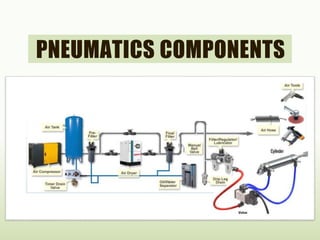
  • 4. AIR GENERATION AND DISTRIBUTION • The generation of compressed air starts with compression. • The compressed air flows through an entire series of components before reaching the consuming device. • The equipment to be considered in the generation and preparation of air include : – Inlet filter – Air compressor – Air reservoir – Air dryer – Air filter with water separator – Pressure regulator – Air lubricator as required – Drainage points
  • 5. INTAKE FILTER • It is used to clean & filter the air used for systems. • Before the surrounding air enters the compressor, it must pass through a filter to remove most of the dirt & other solid contaminants. • These filters can be of dry or wet type depending on the compressor manufacturer & the application.
  • 6. AIR COMPRESSORS • A compressor is the most common industrial energy supply unit that convert mechanical energy into fluid energy. • It is design to take in air at atmospheric pressure and deliver the received air to a closed system with a certain volumetric flow rate, at a higher pressure.
  • 7. RECIPROCATING PISTON COMPRESSORS • A piston compresses the air drawn in via an inlet valve. The air is passed on via an outlet valve. • Reciprocating compressors are very common and provide a wide range of pressures and delivery rates. • For higher pressures multistage compression is used with inter- cooling between each stage of compression.
  • 8. RECIPROCATING PISTON COMPRESSORS • A reciprocating compressor consist of the crankshaft by a connecting rod. • Crankshaft is externally rotate by a electric motor. • Crankshaft & connecting rod convert rotary motion into reciprocating motion.
  • 9. FLOW COMPRESSOR • These are particularly suitable for large delivery quantities. • Flow compressors are made in axial or radial form. The air is made to flow by means of one or several turbine wheels. • The kinetic energy is converted into pressure energy. • In the case of an axial compressor, the air is accelerated in the axial direction of flow by means of blades.
  • 10. RESERVOIRS • A reservoir is configured downstream of a compressor to stabilise compressed air. • A reservoir compensates the pressure fluctuations when the compressed air is taken from the system. • If the pressure in the reservoir drops below a certain value, the compressor will compensate until the set higher value is reached again. • This has the advantage that the compressor does not need to operate continuously.
  • 12. AIR DRYERS • The most common type of dryer today is the refrigeration dryer. • With refrigerated drying, the compressed air is passed through a heat exchanger system through which a refrigerant flows. • The aim is to reduce the temperature of the air to a dew point which ensures that the water in the air condenses and drops out in the quantity required.
  • 13. COMPRESSED AIR FILTER • The selection of the correct filter plays an important role in determining the quality and performance of the working system which is to be supplied with compressed air. • One characteristic of compressed- air filters is the pore size. • The pore size of the filter element indicates the minimum particle size which can be filtered out of the compressed air.
  • 14. LUBRICATOR • Lubrication of the compressed air should therefore always be limited to the plant sections which require lubrication. • For this purpose, lubricators are fitted to feed the compressed air with specially selected oils. • Oils which are introduced into the air from the compressor are suitable for the lubrication of control system components.
  • 15. SERVICE UNIT • The individual functions of compressed air preparation, i.e. filtering, lubricating and regulating , can be fulfilled by individual components. • These functions have often been combined into one unit, i.e. the service unit or FLR. • Service units are connected upstream of all pneumatic systems.
  • 16.
  • 17. ACTUATORS AND OUTPUT DEVICES • An actuator is an output device for the conversion of supply energy into useful work. • The output signal is controlled by the control system, and the actuator responds to the control signals via the control element. • Other types of output devices are used to indicate the status of the control system or actuators, e.g. a pneumatically actuated visual display. • The pneumatic actuator can be described under two groups, linear and rotary : • Linear motion – Single-acting cylinders – Double-acting cylinders • Rotary motion – Air motor – Semi-Rotary actuator
  • 18. SINGLE-ACTING CYLINDERS • With single-acting cylinders compressed air is applied on only one side of the piston face. The other side is open to atmosphere. • The cylinder can produce work in only one direction. The return movement of the piston is effected by a built-in spring or by the application of an external force. • The spring force of the built-in spring is designed to return the piston to its start position with a reasonably high speed under no load conditions.
  • 19. DOUBLE-ACTING CYLINDERS • The construction principle of a double-acting cylinder is similar to that of the single-acting cylinder. • But no return spring, and the two ports are used alternatively as supply and exhaust ports. • The double-acting cylinder has the advantage that the cylinder is able to carry out work in both directions of motion. • The force transferred by the piston rod is somewhat greater for the forward stroke than for the return stroke as the effective piston surface is reduced on the piston rod side by the cross- sectional area of the piston rod.
  • 20. DOUBLE-ACTING CYLINDER WITH CUSHIONING • If large masses are moved by a cylinder, cushioning is used in the end positions to prevent sudden damaging impacts. Before reaching the end position, a cushioning piston interrupts the direct flow path of the air to the outside. • Instead a very small and often adjustable exhaust aperture is open. • For the last part of the stroke the cylinder speed is progressively reduced. If the passage adjustment is too small, the cylinder may not reach the end position due to the blockage of air.
  • 21. TANDEM DOUBLE-ACTING CYLINDER • The tandem cylinder incorporates the features of two double- acting cylinders which have been joined to form a single unit. By this arrangement and with the simultaneous loading of both pistons, the force on the piston rod is almost doubled. • This design is suitable for such applications where a large force is required but the cylinder diameter is restricted.
  • 22. MULTI-POSITION CYLINDERS • The multi-position cylinder consists of two or several double- acting cylinders, which are interconnected. • The individual cylinders advance when pressure is applied. In the case of two cylinders with different stroke lengths, four positions are obtained.
  • 23. ROTARY CYLINDERS • With this design of double-acting cylinder, the piston rod has a geartooth profile. • The piston rod drives a gear wheel, and a rotary movement results from a linear movement. • The range of rotation varies from 45o, 90o, 180o, 270oto 360o. • The torque is dependent on pressure, piston surface and gear ratio; values of roughly up to 150 Nm are possible.
  • 24. DIAPHRAGM CYLINDER • This is the simplest form of single acting cylinder. In diaphragm cylinder , piston is replaced by a diaphragm is replaced by a diaphragm of hard rubber, plastic or metal clamped between the two halves of a metal casing expanded to form a wide, flat enclosure. • The operating stem which takes place of the piston rod in diaphragm cylinder can also be designed as a surface element so as to act directly as a clamping surface for example. • Only short operating strokes can be executed by a diaphragm cylinder, up to a maximum of 50 mm. This makes the diaphragm type of cylinder particularly adaptable to clamping operations. • Return stroke is accomplished by a spring built into the assembly or by the tension of diaphragm itself in the case of very short stroke. • Diaphragm cylinders are used for short stoke application like clamping, riveting, lifting, embossing and riveting
  • 25. AIR MOTORS • Devices which transform pneumatic energy into mechanical rotary movement with the possibility of continuous motion are known as pneumatic motors. • The pneumatic motor with unlimited angle of rotation has become one of the most widely used working elements operating on compressed air. • Pneumatic motors are categorised according to design: – Piston motors – Sliding-vane motors – Gear motors – Turbines (high flow)
  • 26. PNEUMATIC GRIPPERS • Pneumatic grippers – a) Radial grippers – b) Parallel grippers – c) 3-point grippers – d) Angle grippers
  • 27. VACUUM GENERATORS • Handling with suction cups is generally a simple, low-cost and reliable solution. • Suction cups allow the handling of different workpieces with weights ranging from a few grammas right up to several hundred kilo grammas. • They come in a wide variety of different shapes, such as universal, flat or bellows suction cups, for example.
  • 28.
  • 29. 4/1/2016 Sanjay Humania [M.Tech - Mechatronics] 29
  • 30. PNEUMATIC VALVES • Valve is a device which is used to control out put of the circuit. • The main purpose of a valve in pneumatics or hydraulic circuit is to control Final output. • Valves are divided into number of groups according to what they control. • Function – Example: DCV, FCV, PCV. • Design – Example: Spool valve, poppet valve. • Method of actuation – Manual, mechanical, pneumatic, electric. • Mounting angle – Manifold, in line, sub plate. • Application – Speed control, signal processing, proportional valve.
  • 31. GRAPHICAL REPRESENTATION • PORT & POSITIONS TABLE: Port Alphabetic system No. sys. Comment Pressure port P 1 Supply port Working port A 2 3/2 DC valve Working ports A, B 4, 2 4/2 or 5/2 DC valve Exhaust port R 3 3/2 DC valve Exhaust ports R, E,S 3, 5 3/2 DC valve Pilot port Z or Y 12 Pilot line (1 2) Pilot port Z 14 Pilot line (1 4) Pilot port Z or Y 10 Pilot line (flow closed) Internal pilot port Pz, Py 81, 91 Auxiliary pilot air
  • 33. 2/2 WAY VALVE • 2/2 way Normally closed valve • Initially no flow from1 to 2, switched to flow from 1 to 2. figure indicates 2/2 way valve normally closed and that when activated connects pressure port (1) to the output port (2) and therefore it is used for ON/OFF switch. 1 (P) 2 (A)
  • 34. 3/2 WAY VALVE • 3/2 way normally closed valve • Initially no flow from 1to 2 but flow from 2 to 3 switched to flow from 1 to 2 and 3 closed. • Figure shows 3/2 way valve normally closed in which pressure port 1 is off and output port (2) exhausting via exhaust port (3). when it is activated the pressure is applied to the output port directly and the exhaust port will be closed. 2 1 3
  • 35. 4/2 WAY VALVE • 4/2 way valve • Initially flow from 1 to 2 and 4 to 3.switched to flow or from 1 to 4 and from 2 to 3. A 4/2 way valve is shown in figure in which pressure is applied to the output port while the output port exhaust through the exhaust port. When activated the pressure port (1) is connected to the output port (4) while output port (2) exhaust through the exhaust port (3). 4 2 1 3
  • 36. 5/2 WAY VALVE • 5/2 way valve • Initially flow from 1 to 2 and flow 4 to 5, 3 closed. Switched to flow from 1 to 4 and from 2 to 3, 5 closed. Figure indicates 5/2 way valve in which pressure is applied to the output port while output port exhaust through the exhaust port. When activated pressure (1) is connected to the output port (4) exhaust through exhaust port (5) 3 will be closed. 4 2 1 5 3
  • 45. LOGICS 4/1/2016 Sanjay Humania [M.Tech - Mechatronics] 45 • AND logic • OR logic • NOT logic • NAND logic • NOR logic • EX-OR logic
  • 46. PNEUMATIC PRESET COUNTER The pneumatic preset counter counts pneumatic signals, decrementing from a preset number. When zero is reached, the counter emits a pneumatic output signal. It has 4 ports 1 (P) – pressure port / input port 2 (A) – output port 12 (Z) – pulse counting port 10 (Y) – Reset port