
Empfohlen
Weitere ähnliche Inhalte
Empfohlen
Empfohlen (20)
Manuel kit robot
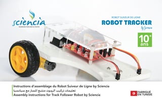
- 1. SCIENCES FOR KIDS & YOUTH FABRIQUÉ EN TUNISIE Instructions d’assemblage du Robot Suiveur de Ligne by Sciencia Assembly instructions for Track Follower Robot by Sciencia ﺳﻴﺎﻧﺴﻴﺎ ﻣﻊ ﺍﳌﺴﺎﺭ ﻣﺘﺘﺒﻊ ﺍﻟﺮﻭﺑﻮﺕ ﺗﺮﻛﻴﺐ ﺗﻌﻠﻴﻤﺎﺕ
- 2. SCIENCES FOR KIDS & YOUTH Notes Notesﻣﻼﺣﻅﺎﺕ
- 3. SCIENCES FOR KIDS & YOUTH Sommaire Contentﻓﻬﺭﺱ Module Electronique Prépara�on Comment Assembler Comment Braser Jeu de Lumière Control Moteur Module Mécanique Assemblage Moteurs Assemblage Roues Assemblage Pile Assemblage Carte Assemblage Capteurs Assemblage Cockpit Test & Circuit Electronics Module Prepara�on How to Assemble How to Solder Light Show Circuit Motor Control Circuit Mechanial Module Motors Assembly Wheels Assembly Ba�ery Asseembly PC Board Assembly Sensors Assembly Cockpit Assembly Test & Circuit 04 07 11 15 18 29 37 38 43 45 46 54 59 63 إﻟﻜﺘﺮوﻧﻴﺔ وﺣﺪة اﻟﺘﺤﻀﻴﺮ ﺗﺮﻛﻴﺐ ﻛﻴﻔﻴﺔ ﻟﺤﺎم ﻛﻴﻔﻴﺔ اﻟﻀﻮء ﻋﺮض داﺋﺮة اﻟﻤﺤﺮﻛﺎت ﻓﻲ اﻟﺘﺤﻜﻢ دارة ﻣﻴﻜﺎﻧﻴﻜﻴﺔ وﺣﺪة اﻟﻤﺤﺮﻛﺎت ﺗﺮﻛﻴﺐ اﻟﻌﺠﻼت ﺗﺮﻛﻴﺐ اﻟﺒﻄﺎرﻳﺔ ﺗﺮﻛﻴﺐ اﻻﻟﻜﺘﺮوﻧﻴﺔ اﻟﻠﻮﺣﺔ ﺗﺮﻛﻴﺐ اﻟﻤﺴﺘﺸﻌﺮ ﺗﺮﻛﻴﺐ اﻟﺠﺴﻢ ﺗﺮﻛﻴﺐ وداﺋﺮة اﺧﺘﺒﺎر ...................................................................................... ........................................... ........................................... ........................................... ........................................... ........................................... ........................................... ........................................... ........................................... ........................................... ........................................... ........................................... ..................................................... ..................................................................... .............................................................. ....................................... ................................................. ......................................................... ................................................................ ..................................... ............................................ ..................................................... ............................... ....................................... ...................................... ........................................ ......................................... .......................................... .......................................... ........................................ ........................................ .................................................. ......................................................
- 4. SCIENCES FOR KIDS & YOUTH Module Electronique - Sans Brasage Electronics Module - Solderless ﻟﺤﺎم ﺑﺪون - إﻟﻜﺘﺮوﻧﻴﺔ وﺣﺪة 04
- 5. SCIENCES FOR KIDS & YOUTH 05 Voici la face ‘supérieure’ de la carte imprimée, dite PCB (Printed Circuit Board). Les composants électroniques seront placés sur ce�e face, sur laquelle les noms (références) et les symboles des composants sont écrits pour faciliter l’assemblage. ﺍﻟﻣﻁﺑﻭﻋﺔ ﺍﻻﻟﻛﺗﺭﻭﻧﻳﺔ ﺍﻟﻠﻭﺣﺔ ﻣﻥ ""ﺍﻟﻌﻠﻭﻱ ﺍﻟﺟﺎﻧﺏ ﻫﻭ ﻫﺫﺍ .ﺍﻟﻭﺟﻪ ﻫﺫﺍ ﻋﻠﻰ ﺍﻻﻟﻛﺗﺭﻭﻧﻳﺔ ﺍﻟﻣﻛﻭﻧﺎﺕ ﺑﻭﺿﻊ ﻧﻘﻭﻡ .(PCB) ﺭﻣﻭﺯﻫﺎ ﻭﻛﺫﻟﻙ (ﺍﻟﻣﺭﺍﺟﻊ )ﺗﺳﻣﻰ ﺍﻟﻣﻛﻭﻧﺎﺕ ﺃﺳﻣﺎء ﺗﻭﺟﺩ ﻟﻬﺫﺍ .ﺍﻟﺗﺭﻛﻳﺏ ﻟﺗﺳﻬﻳﻝ ﺍﻟﻭﺟﻪ ﻫﺫﺍ ﻋﻠﻰ ﻣﻛﺗﻭﺑﺔ Voici la face ‘supérieure’ de la carte imprimée, dite PCB (Printed Circuit Board). Les composants électroniques seront placés sur ce�e face, sur laquelle les noms (références) et les symboles des composants sont écrits pour faciliter l’assemblage.
- 6. SCIENCES FOR KIDS & YOUTH 06 Voici la face ‘inférieure’ de la carte sur laquelle nous allons faire la brasure des composants. ﺳﻧﻘﻭﻡ ، ﺍﻟﻭﺟﻪ ﻫﺫﺍ ﻋﻠﻰ .ﺍﻟﻠﻭﺣﺔ ﻣﻥ ""ﺍﻟﺳﻔﻠﻲ ﺍﻟﺟﺎﻧﺏ ﻫﻭ ﻫﻧﺎ .ﺍﻟﻣﻛﻭﻧﺎﺕ ﻟﺣﺎﻡ ﺑﻌﻣﻠﻳﺔ Here is the “bo�om” side of the board. On this face, we will do the soldering of the components.
- 7. SCIENCES FOR KIDS & YOUTH 07 Préparons les composants avant de les assembler. Chaque composant est fragile. Essayons d’être délicat pour ne pas les endommager. Commençons par les Résistances ! Avec une pince ou juste avec les doigts, plions délicatement les deux broches des résistances juste au début comme dans l’image. .ﺗﺭﻛﻳﺑﻬﺎ ﻗﺑﻝ ﺍﻟﻣﻛﻭﻧﺎﺕ ﻟﻧﺣﺿﺭ ﺩﻗﻳﻘﻳﻥ ﻧﻛﻭﻥ ﺃﻥ ﺇﻟﻰ ﺑﺣﺎﺟﺔ ﻧﺣﻥ .ﺍﻟﺣﺫﺭ ﻳﻠﺯﻡ ﻭ ﺭﻗﻳﻘﺔ ﺍﻟﻣﻛﻭﻧﺎﺕ .ﺇﺗﻼﻓﻬﺎ ﻟﺗﺟﻧﺏ ﺑﺛﻧﻲ ﻗﻡ ، ﺑﺎﻷﺻﺎﺑﻊ ﺃﻭ ﻣﻠﻘﻁ ﺑﺎﺳﺗﻌﻣﺎﻝ ! ﺍﻟﻣﻘﺎﻭﻣﺎﺕ ﻣﻊ ﻟﻧﺑﺩﺃ ﺍﻟﺟﺳﻡ ﻣﻥ ﺑﺎﻟﻘﺭﺏ ﻗﺎﻋﺩﺗﻬﺎ ﻋﻠﻰ ﺑﻠﻁﻑ ()ﺍﻟﻭﺻﻼﺕ ﺍﻷﺭﺟﻝ .ﺍﻟﺭﺳﻡ ﻓﻲ ﻣﻭﺿﺢ ﻫﻭ ﻛﻣﺎ ﺍﻟﻣﺭﻛﺯﻱ Let’s prepare the components before assembling them. Every component is fragile. We need to be delicate to avoid damaging them. Let’s start with Resistors! With some pliers or just with our fingers, gently bend the legs (leads) on their base close to the central body as shown in the figure.
- 8. SCIENCES FOR KIDS & YOUTH 08 Assemblage des Résistances Le montage des résistances est très simple. Il n’y a pas d’orienta�on à respecter. Le rectangle indique le corps de la résistance. ‘R1’ indique le nom (référence). Il suffit d’introduire les broches de la résistance dans les emplacements de part et d’autre du rectangle de la référence souhaitée. ﺍﻟﻣﻘﺎﻭﻣﺎﺕ ﺗﺭﻛﻳﺏ .ﻟﻭﺿﻌﻪ ﻣﺣﺩﺩ ﺍﺗﺟﺎﻩ ﻳﻭﺟﺩ ﻻ .ﺟﺩﺍ ﺑﺳﻳﻁ ﺍﻟﻣﻘﺎﻭﻣﺔ ﺗﺭﻛﻳﺏ ﺍﻻﺳﻡ ﺇﻟﻰ ‘1R‘ﻳﺷﻳﺭ .ﺍﻟﻣﻘﺎﻭﻣﺔ ﺟﺳﻡ ﻣﻛﺎﻥ ﺇﻟﻰ ﻳﺷﻳﺭ ﺍﻟﻣﺳﺗﻁﻳﻝ .()ﺍﻟﻣﺭﺟﻊ ﻓﻲ ﺍﻟﻣﻭﺟﻭﺩﺓ ﺍﻟﻣﻘﺎﺑﺱ ﻓﻲ ﺍﻟﻭﺻﻼﺕ ﺿﻊ ، ﺍﻟﻣﻘﺎﻭﻣﺔ ﻟﺗﺭﻛﻳﺏ .ﺍﻟﻣﻁﻠﻭﺏ ﺍﻟﻣﺭﺟﻊ ﺍﻟﻣﺳﺗﻁﻳﻝ ﻣﻥ ﺟﺎﻧﺏ ﻛﻝ Resistors Assembly The assembly of the resistors is very simple. There is no specific orienta�on to place it. The rectangle indicates the resistor body place. ‘R1’ indicates the name (designator). To assemble the resistor, place the leads in the sockets on each side the rectangle of the desired designator..
- 9. SCIENCES FOR KIDS & YOUTH 09 Au tour des transistors. Maintenant, ça sera un peu plus délicat. Prenons chaque transistor. Ensuite, avec une pince fine, ou précisément avec nos doigts, plier la broche centrale en avant vers la par�e arrondie du transistor et ensuite la rendre ver�cale et parallèle aux autres broches. Les transistors devront ressembler à la figure. .ﺩﻗﺔ ﺃﻛﺛﺭ ﻳﺗﻁﻠﺑﻭﻥ ﺍﻟﻠﺫﻳﻥ ﺍﻟﺗﺭﺍﻧﺯﺳﺗﻭﺭﺍﺕ ﻭﻗﺕ ﺣﺎﻥ ﻗﻡ ، ﺑﺄﺻﺎﺑﻌﻧﺎ ﺃﻭ ﺍﻟﺩﻗﻳﻖ ﺍﻟﻣﻠﻘﺎﻁ ﺑﺎﺳﺗﺧﺩﺍﻡ ﻭ ﺍﻟﺗﺭﺍﻧﺯﺳﺗﻭﺭ ﻟﻧﺄﺧﺫ ﺍﻟﺟﺳﻡ ﻣﻥ ﺍﻟﻣﺳﺗﺩﻳﺭ ﺍﻟﺟﺯء ﻧﺣﻭ ﺍﻷﻣﺎﻡ ﺇﻟﻰ ﺍﻻﻭﺳﻁ ﺍﻟﻭﺻﻝ ﺑﺛﻧﻲ .ﺍﻷﺧﺭﻯ ﻟﻠﻭﺻﻼﺕ ﻣﻭﺍﺯﻳﺎ ﺿﻌﻪ ﺛﻡ .ﺍﻟﺻﻭﺭﺓ ﻣﺛﻝ ﺍﻟﺗﺭﺍﻧﺯﺳﺗﻭﺭﺍﺕ ﺗﻛﻭﻥ ﺃﻥ ﻳﺟﺏ And now, �me for the transistors. It’s going to be more delicate. Let’s take each transistor. Then, with fine pliers or precisely with our fingers, bend the central leg (lead) to the front towards the rounded part of the body and then place it ver�cally parallel to the other legs. The transistors should look like the picture.
- 10. SCIENCES FOR KIDS & YOUTH 10 Assemblage des Transistors Le transistor a 3 broches, et nous avons déjà plié celle du milieu lors de la prépara�on. Le transistor se monte en suivant les contours dessinés sur la carte : La face plate du transistor s’aligne avec la ligne droite sur la carte; La face arrondie du transistor s’aligne avec la ligne arrondie sur la carte. La broche du milieu se place du côté arrondi. ﺍﻟﺗﺭﺍﻧﺯﺳﺗﻭﺭﺍﺕ ﺗﺭﻛﻳﺏ ﺑﺗﻘﺩﻳﻡ ﻭﻗﻣﻧﺎ ﺳﺑﻖ ﻭﻗﺩ ﻭﺻﻼﺕ 3 ﻋﻠﻰ ﺍﻟﺗﺭﺍﻧﺯﺳﺗﻭﺭ ﻳﺣﺗﻭﻱ .ﺍﻟﺗﺣﺿﻳﺭ ﺃﺛﻧﺎء ﺍﻻﻭﺳﻁ ﺍﻟﻭﺻﻝ ﻋﻠﻰ ﺍﻟﻣﺭﺳﻭﻡ ﺍﻟﺗﻔﺻﻳﻠﻲ ﻟﻠﻣﺧﻁﻁ ﺗﺑﻌﺎ ﺍﻟﺗﺭﺍﻧﺯﺳﺗﻭﺭ ﻭﺿﻊ ﻳﺗﻡ ﺍﻟﻣﺳﺗﻘﻳﻡ ﺍﻟﺧﻁ ﻣﻊ ﻳﺗﻣﺎﺷﻰ ﻟﻠﺗﺭﺍﻧﺯﺳﺗﻭﺭ ﺍﻟﻣﺳﻁﺢ ﺍﻟﻭﺟﻪ :ﺍﻟﻠﻭﺣﺔ ﺍﻟﻣﺳﺗﺩﻳﺭ ﺍﻟﺧﻁ ﻣﻊ ﻟﻠﺗﺭﺍﻧﺯﺳﺗﻭﺭ ﺍﻟﻣﺳﺗﺩﻳﺭ ﺍﻟﻭﺟﻪ ؛ ﺍﻟﻠﻭﺣﺔ ﻋﻠﻰ .ﺍﻟﻠﻭﺣﺔ ﻋﻠﻰ ﺍﻟﺗﻔﺻﻳﻠﻲ .ﺍﻟﻠﻭﺣﺔ ﺍﻟﻣﺳﺗﺩﻳﺭﻋﻠﻰ ﺍﻟﺧﻁ ﻗﺭﺏ ﺍﻻﻭﺳﻁ ﺍﻟﻭﺻﻝ ﻭﺿﻊ ﻳﺗﻡ Transistors Assembly The transistor has 3 leads and we have already formed the central one during prepara�on. The transistor is placed following the outline drawn on the PCB : The flat face of the transistor goes with the straight line on the PCB; The rounded face of the transistor goes with the rounded outline on the PCB. The central lead is placed on the rounded outline.
- 11. SCIENCES FOR KIDS & YOUTH 11 Assemblage des Diodes DEL Les diodes électroluminescentes (DEL) ont une orienta�on spécifique de placement. La Cathode ou borne ‘-’ est indiquée sur la carte par le point et la droite. Ceci correspond à la par�e plate de la DEL. En plus, sur la DEL, la broche la plus longue est la borne ‘+’ ou Anode En regardant à l’intérieur de la DEL, la par�e métallique la plus grande correspond à la borne ‘-’ (Cathode), ﻟﻠﺿﻭء ﺍﻟﺑﺎﻋﺙ ﺍﻟﺻﻣﺎﻡ ﺗﺭﻛﻳﺏ .ﻣﺣﺩﺩ ﺍﺗﺟﺎﻩ ﺣﺳﺏ ﺗﻭﺿﻊ (LED) ﻟﻠﺿﻭء ﺍﻟﺑﺎﻋﺛﺔ ﺍﻟﺛﻧﺎﺋﻳﺎﺕ ﻭﺧﻁ ﺑﻧﻘﻁﺔ ﺍﻟﻠﻭﺣﺔ ﻋﻠﻰ ‘-’ ﺍﻟﺳﻠﺑﻲ ﺍﻟﻭﺻﻝ ﺃﻭ ﺍﻟﻛﺎﺛﻭﺩ ﺇﻟﻰ ﻳﺷﺎﺭ .ﺍﻟﺻﻣﺎﻡ ﻣﻥ ﺍﻟﻣﺳﻁﺢ ﺍﻟﺟﺎﻧﺏ ﻣﻊ ﻳﺗﻭﺍﻓﻖ ﻫﺫﺍ . ﻋﻣﻭﺩﻱ ﺍﻟﺟﺎﻧﺏ ﺍﻟﻰ ﻳﺷﻳﺭ ﺍﻷﻁﻭﻝ ﺍﻟﻭﺻﻝ ﻓﺈﻥ ، ﺫﻟﻙ ﺇﻟﻰ ﺑﺎﻹﺿﺎﻓﺔ .ﺍﻻﻧﻭﺩ ﺃﻭ ‘+’ ﺍﻻﺟﺎﺑﻲ ﻫﻭ ﺍﻷﻛﺑﺭ ﺍﻟﻣﻌﺩﻧﻲ ﺍﻟﺟﺯء ﻓﺈﻥ ، ﺍﻟﺻﻣﺎﻡ ﺩﺍﺧﻝ ﺇﻟﻰ ﻧﻅﺭﻧﺎ ﺇﺫﺍ .‘-’ ﺍﻟﺧﻳﻁ ﺃﻭ ﺍﻟﻛﺎﺛﻭﺩ LED Assembly The Light Emi�ng Diodes (LED) have a specific orienta�on for placement. The Cathode or ‘-’ lead is indicated on the PCB by a point and a line. This corresponds to the flat side of the LED. In addi�on, the longer lead of the LED is the ‘+’ or Anode lead. Looking inside the LED, the bigger metallic part is the Cathode or ‘-’ lead.
- 12. SCIENCES FOR KIDS & YOUTH 12 Assemblage des Condensateurs Certains condensateurs dits polarisés ont une orienta�on spécifique alors que d’autres n’ont en pas (non-polarisés). Dans le cas d’un condensateur polarisé, la polarisa�on est indiquée souvent par ‘-’ pour la borne néga�ve. Sur la carte, le signe ‘-’ correspond à la polarisa�on/borne néga�ve du condensateur. ﺍﻟﻣﻛﺛﻔﺎﺕ ﺗﺭﻛﻳﺏ ﻟﻠﺗﺭﻛﻳﺏ ﻣﺣﺩﺩ ﺍﺗﺟﺎﻩ ﻟﻬﺎ ، ﻗﻁﺑﻳﺔ ﺗﺳﻣﻰ ﺍﻟﺗﻲ ، ﺍﻟﻣﻛﺛﻔﺎﺕ ﺑﻌﺽ .(ﻣﺳﺗﻘﻁﺏ )ﻏﻳﺭ ﻣﻌﻳﻥ ﺍﺗﺟﺎﻩ ﻟﻪ ﻟﻳﺱ ﺍﻵﺧﺭ ﺍﻟﺑﻌﺽ ﺑﻳﻧﻣﺎ ، ﺑﻌﻼﻣﺔ ًﺎﺑﻏﺎﻟ ﺍﻻﺳﺗﻘﻁﺎﺏ ﺇﻟﻰ ُﺷﺎﺭﻳ ، ﺍﻟﻘﻁﺑﻲ ﺍﻟﻣﻛﺛﻑ ﺣﺎﻟﺔ ﻓﻲ .ﺍﻟﺳﻠﺑﻲ ﻟﻠﻭﺻﻝ ‘-’ ﺍﻟﺳﺎﻟﺑﻲ ﺍﻟﻭﺻﻝ / ﺍﻟﻘﻁﺏ ﺇﻟﻰ ﻟﻺﺷﺎﺭﺓ ‘-’ ﺍﻟﻌﻼﻣﺔ ﺍﻟﻠﻭﺣﺔ ﺗﺣﻣﻝ .ﻟﻠﻣﻛﺛﻑ Capacitors Assembly Some capacitors, called polarized, have a specific orienta�on for assembly, while other do not (non-polarized). In the case of a polarized capacitor, the polariza�on is o�en indicated with a ‘-’ for the nega�ve lead. The PCB will bear the mark ‘-’ to indicate the nega�ve polariza�on/lead of the capacitor.
- 13. SCIENCES FOR KIDS & YOUTH 13 Assemblage des Connecteurs Les connecteurs sont déjà brasés dans ce�e version. Les connecteurs n’ont pas d’orienta�on spécifique. Les broches sont rigides et ne doivent pas être pliées. ﺍﻟﺭﻭﺍﺑﻁ ﺗﺭﻛﻳﺏ ﻣﺳﺑﻘﺎ ﺍﻟﻭﺻﻼﺕ ﻟﺣﺎﻡ ,ﺗﻡ ﺍﻻﺻﺩﺍﺭ ﻫﺫﺍ ﻓﻲ ﻋﺩﻡ ﻭﻳﺟﺏ ﻟﻳﻧﺔ ﻟﻳﺳﺕ ﺍﻟﻭﺻﻼﺕ .ﺍﺗﺟﺎﻩ ﺃﻱ ﺍﻟﺭﻭﺍﺑﻁ ﺗﺗﻁﻠﺏ ﻻ .ﺛﻧﻳﻬﺎ Connectors Assembly The connectors are already soldered in this version. Connectors do not require any orienta�on. Leads are not so� and should not be bent.
- 14. SCIENCES FOR KIDS & YOUTH 14 Assemblage des interrupteurs L’interrupteur est déjà brasé dans ce�e version. L’interrupteur ne requiert aucune orienta�on puisqu’il s’agit d’un interrupteur à 2 posi�ons et à un seul circuit. ﺍﻟﻣﻘﻼﺩ ﺗﺭﻛﻳﺏ ﻣﺳﺑﻘﺎ ﺍﻟﻣﻘﻼﺩ ﻟﺣﺎﻡ ,ﺗﻡ ﺍﻻﺻﺩﺍﺭ ﻫﺫﺍ ﻓﻲ ﺍﻟﻔﺭﺩﻱ ﺍﻟﻘﻁﺏ ﺑﺳﻳﻁ ﻣﻘﻼﺩ ﻷﻧﻪ ﺍﺗﺟﺎﻩ ﺃﻱ ﻋﻠﻰ ﺍﻟﻣﻘﻼﺩ ﻳﺣﺗﻭﻱ ﻻ .ﻣﻭﺿﻌﻳﻥ ﺫﺍﺕ ﻭﺍﺣﺩﺓ ﺩﺍﺋﺭﺓ ﻳﻌﻧﻲ ﺍﻟﻣﺯﺩﻭﺟﺔ ﺍﻟﺭﻣﻳﺎﺕ - Switch Assembly The switch is already soldered in this version. The Switch does not have any orienta�on as it’s an SPDT (Single Pole – Dual Throws) meaning one circuit with 2 posi�ons.
- 15. SCIENCES FOR KIDS & YOUTH 15 Dans ce�e version sans brasage du kit, les instruc�ons suivantes sont décrites sans les connecteurs de composants, pour avoir une meilleure lecture de la carte. Les connecteurs de composants sont perme�ent un assemblage sans brasage. ﺍﻟﺗﺎﻟﻳﺔ ﺍﻹﺭﺷﺎﺩﺍﺕ ﻋﺭﺽ ﺳﻳﺗﻡ ،ﻟﺣﺎﻡ ﺑﺩﻭﻥ ﺍﻹﺻﺩﺍﺭ ﻫﺫﺍ ﻓﻲ ﻋﻣﻠﻳﺔ ﻟﺗﺳﻬﻳﻝ ﻟﻠﻣﻛﻭﻧﺎﺕ ﻻﻟﺣﺎﻣﻠﺔ ﻟﻠﻣﻛﻭﻧﺎﺕ ﺑﺎﻻﻋﺗﺑﺎﺭ ﺃﺧﺫ ﺑﺩﻭﻥ ﻓﻘﻁ ﺗﻣﻛﻥ ﺍﻟﻣﻛﻭﻧﺎﺕ ﻫﺫﻩ .ﺍﻻﺭﺷﺎﺩﺍﺕ ﺗﻭﺿﻳﺢ ﻭ ﺍﺍﺗﺭﻛﻳﺏ .ﻟﺣﺎﻡ ﺑﺩﻭﻥ ﺍﻟﺗﺟﻣﻳﻊ In this solderless version of the kit, the following instruc�ons will be shown without the sockets for components assembly for a be�er understanding of the procedure. The sockets enables only the assembly without soldering.
- 16. SCIENCES FOR KIDS & YOUTH 16 Commençons par le jeu de lumière. Ce circuit est simple avec quelques composants mais il donne un effet grandiose au robot. Iln’apasbesoindurestedurobotpourfonc�on- ner, donc, il est le meilleur départ pour apprendre. .ﺍﻟﺿﻭء ﻋﺭﺽ ﺑﺩﺍﺋﺭﺓ ﻟﻧﺑﺩﺃ ﺗﺑﺩﻭ ﻟﻛﻧﻬﺎ ﺍﻟﻣﻛﻭﻧﺎﺕ ﺑﻌﺽ ﺇﻻ ﺗﺳﺗﻠﺯﻡ ﻭﻻ ﺑﺳﻳﻁﺔ ﺍﻟﺩﺍﺋﺭﺓ ﻫﺫﻩ .ﺍﻟﺭﻭﺑﻭﺕ ﻋﻠﻰ ﺭﺍﺋﻌﺔ ﻧﻘﻁﺔ ﺃﻓﺿﻝ ﻓﻬﻲ ، ﻭﺑﺎﻟﺗﺎﻟﻲ .ﻟﻠﻌﻣﻝ ﺍﻟﺭﻭﺑﻭﺕ ﺑﻘﻳﺔ ﺗﺗﻁﻠﺏ ﻻ ﺃﻧﻬﺎ .ﻟﻠﺗﻌﻠﻡ ﺑﺩﺍﻳﺔ Let’s start with the light show circuit. This circuit is simple with few components but it looks fantas�c on the robot. It does not require the rest of the robot to func�on. Thus, it’s the best start point to learn.
- 17. SCIENCES FOR KIDS & YOUTH 17 Prenons deux Résistances (Marron-Noir-Rouge) et installons les en R1 et R2. Insérons chaque résistance au-dessus du rectangle avec les broches dans les trous autour du rectangle. R1 ﻓﻲ ﻧﺭﻛﺑﻬﺎ ﻭ ()ﺑﻧﻲ-ﺃﺳﻭﺩ-ﺃﺣﻣﺭ ﻣﻘﺎﻭﻣﺎﺕ 2 ﻧﺄﺧﺫ ﺩﻋﻧﺎ .R2 ﻭ ﺩﺍﺧﻝ ﺍﻟﻭﺻﻼﺕ ﺿﻊ ﺛﻡ ، ﺍﻟﻣﺳﺗﻁﻳﻝ ﺃﻋﻠﻰ ﻓﻲ ﻣﻘﺎﻭﻡ ﻛﻝ ﺃﺩﺧﻝ .ﺍﻟﻣﺳﺗﻁﻳﻝ ﺟﺎﻧﺑﻲ ﻋﻠﻰ ﺍﻟﻣﻭﺟﻭﺩﺓ ﺍﻟﺛﻘﺏ Let’s take 2 Resistors (Brown-Black-Red) and assemble them in R1 and R2. Insert each resistor on top of the rectangle and place the leads inside the holes on the sides of the rectangle.
- 18. SCIENCES FOR KIDS & YOUTH 18 Prenons deux Résistances (Marron-Noir- Orange) et installons les en R3 et R4. Insérons chaque résistance au-dessus du rectangle avec les broches dans les trous autour du rectangle. Let’s take 2 Resistors (Brown-Black-Orange) and assemble them in R3 and R4. Insert each resistor on top of the rectangle and place the leads inside the holes on the sides of the rectangle. ﻭ 3R ﻓﻲ ﻧﺭﻛﺑﻬﺎ ﻭ (ﻣﻘﺎﻭﻣﺎﺕ)ﺑﻧﻲ-ﺃﺳﻭﺩ-ﺑﺭﺗﻘﺎﻟﻲ 2 ﺑﺄﺧﺫ ﻗﻡ .4R ﺩﺍﺧﻝ ﺍﻟﻭﺻﻼﺕ ﺿﻊ ﺛﻡ ، ﺍﻟﻣﺳﺗﻁﻳﻝ ﺃﻋﻠﻰ ﻓﻲ ﻣﻘﺎﻭﻡ ﻛﻝ ﺃﺩﺧﻝ .ﺍﻟﻣﺳﺗﻁﻳﻝ ﺟﺎﻧﺑﻲ ﻋﻠﻰ ﺍﻟﻣﻭﺟﻭﺩﺓ ﺍﻟﺛﻘﺏ
- 19. SCIENCES FOR KIDS & YOUTH 19 Pour les DEL, tu peux choisir la configura�on de couleur que tu veux. Commençons par installer D3 et D4, qui sont les plus faciles, en respectant la polarisa�on, avec la par�e plate de la DEL posi�onnée avec la droite imprimée sur la carte. ﺗﺭﺗﻳﺏ ﺃﻱ ﺍﺧﺗﻳﺎﺭ ﻳﻣﻛﻧﻙ ،ﻟﻠﺿﻭء ﺍﻟﺑﺎﻋﺛﺔ ﻟﻠﺻﻣﺎﻣﺎﺕ ﺑﺎﻟﻧﺳﺑﺔ .ﺗﺭﻳﺩ ﺍﻟﺗﻲ ﻟﻸﻟﻭﺍﻥ ﺍﺳﺗﻘﻁﺎﺏ ﻣﺭﺍﻋﺎﺓ ﻣﻊ ، ﺍﻟﺗﺭﻛﻳﺏ ﻟﺳﻬﻭﻟﺔ D4ﻭ D3 ﻣﻊ ﻟﻧﺑﺩﺃ ﺍﻟﻣﺳﺗﻘﻳﻡ ﺍﻟﺧﻁ ﻋﻠﻰ ﻳﺿﻊ ﺍﻟﺻﻣﺎﻡ ﻣﻥ ﺍﻟﻣﺳﻁﺢ ﺍﻟﺟﺎﻧﺏ : ﺍﻟﺻﻣﺎﻡ .ﺍﻟﻠﻭﺣﺔ ﻋﻠﻰ ﺍﻟﻣﻁﺑﻭﻉ For the LED’s, you can choose any configura�on of the colors you want. Let’s start with D3 and D4 for ease of installa�on, respec�ng the polariza�on of the LED with the flat side of the LED placed on the line printed on the PCB.
- 20. SCIENCES FOR KIDS & YOUTH 20 Passons à D1 et D5. Nous pouvons aussi tester les différentes couleurs avant de décider et d’assembler les DEL. . 5Dﻭ 1D ﺩﻭﺭ ﺣﺎﻥ ﺍﻟﺷﻛﻝ ﺍﺧﺗﻳﺎﺭ ﻗﺑﻝ ﺍﻟﻣﺧﺗﻠﻔﺔ ﺍﻷﻟﻭﺍﻥ ﺗﺭﺗﻳﺑﺎﺕ ﺗﺟﺭﺑﺔ ًﺎﺿﺃﻳ ﻳﻣﻛﻧﻧﺎ .ﺍﻟﻧﻬﺎﺋﻲ Let’s move then to D1 and D5 We can also install the LED’s to test the different colour configura�ons before se�ling for one.
- 21. SCIENCES FOR KIDS & YOUTH 21 D2 et D6 devraient être les dernières à être installées. D1-D2-D3 vont s’allumer quand D4-D5-D6 vont s’éteindre et vice-versa. Ceci fonc�onnera bien tant que les 3 couleurs Rouge-Jaune-Verte des DEL sont u�lisées. U�liser uniquement des DEL blanches par exemple n’aura pas un résultat appréciable. .ﺗﺛﺑﻳﺗﻪ ﻳﺗﻡ ﻣﺎ ﺁﺧﺭ D6ﻭ D2 ﻳﻛﻭﻥ ﺃﻥ ﻳﺟﺏ ﻭﺍﻟﻌﻛﺱ D4-D5-D6 ﺗﻧﻁﻔﺄ ﻋﻧﺩﻣﺎ D1-D2-D3ﺗﺳﺗﺿﻳﺄ ﺍﻟﺛﻼﺛﺔ ﺍﻷﻟﻭﺍﻥ ﺍﺳﺗﺧﺩﺍﻡ ﻳﺗﻡ ﻁﺎﻟﻣﺎ ﺟﻳﺩﺓ ﺍﻟﻧﺗﻳﺟﺔ ﺳﺗﻛﻭﻥ .ﺑﺎﻟﻌﻛﺱ .ﻭﺍﻷﺻﻔﺭ ﻭﺍﻷﺧﺿﺭ ﺍﻷﺣﻣﺭ ﻟﻠﺻﻣﺎﻣﺎﺕ ﺍﻟﺣﺻﺭﻱ ﺍﻻﺳﺗﺧﺩﺍﻡ ﺗﻡ ﺇﺫﺍ ﻣﺭﺿﻳﺔ ﺗﻛﻭﻥ ﻟﻥ ﺍﻟﻧﺗﻳﺟﺔ .ﻣﺛﻼ ﺍﻟﺑﻳﺿﺎء D2 and D6 should be the last ones to be installed. D1-D2-D3 will turn on when D4-D5-D6 will turn off and vice-versa. It will work fine as long as the 3 colors Red-Green-Yellow are being used. Using exclusively white LED’s will have circuit which will not be working fine.
- 22. SCIENCES FOR KIDS & YOUTH 22 Con�nuer avec les capacitances C1 et C2. La polarisa�on des capacitances doit être respectée avec les signes ‘-’ sur les capacitances et sur la carte alignés. .2C ﻭ 1C ﺍﻟﻣﻛﺛﻔﺎﺕ ﺍﻟﻣﻛﺛﻔﺎﺕ ﻳﺧﺹ ﻓﻳﻣﺎ ﻣﻛﺛﻑ ﻛﻝ ﻋﻠﻰ "-" ﺍﻟﻌﻼﻣﺎﺕ ﺑﺎﺗﺑﺎﻉ ﺍﻻﺳﺗﻘﻁﺎﺏ ﺍﺣﺗﺭﺍﻡ ﻳﺟﺏ .ﺍﻟﻠﻭﺣﺔ ﻋﻠﻰ ﺍﻟﻌﻼﻣﺔ ﻧﻔﺱ ﻣﻊ ﺫﻟﻙ ﻭﻣﻁﺎﺑﻘﺔ Let’s move now to capacitors C1 and C2. The polariza�on of the capacitors should be respected following the signs ‘-’ on both the capacitor and the PCB matching.
- 23. SCIENCES FOR KIDS & YOUTH 23 Maintenant, nous avons le composant le plus complexe. Les transistors Q1 et Q2. Les transistors ont été préparés avec la broche du milieu avancée vers la par�e arrondie. Il suffit de placer le transistor en suivant les contours du transistor et les contours imprimés sur la carte. ﺍﻟﺗﺭﺍﻧﺯﺳﺗﻭﺭ :ًﺍﺩﺗﻌﻘﻳ ﺍﻷﻛﺛﺭ ﺍﻟﻣﻛﻭﻥ ﻟﺗﺛﺑﻳﺕ ﺍﻟﻭﻗﺕ ﺣﺎﻥ ، ﺍﻵﻥ .2Q ﻭ 1Q ﺑﺎﺗﺟﺎﻩ ﺍﻷﻭﺳﻁ ﺍﻟﻭﺻﻝ ﺑﺛﻧﻲ ﻣﺳﺑﻘﺎ ﺍﻟﺗﺭﺍﻧﺯﺳﺗﻭﺭﺍﺕ ﺇﻋﺩﺍﺩ ﺗﻡ ﻭﺍﻟﻣﺧﻁﻁ ﺷﻛﻠﻪ ﺑﺎﺗﺑﺎﻉ ﺍﻟﺗﺭﺍﻧﺯﺳﺗﻭﺭ ﻳﺿﻊ .ﺍﻟﻣﺳﺗﺩﻳﺭ ﺍﻟﺟﺎﻧﺏ .ﺍﻟﻠﻭﺣﺔ ﻋﻠﻰ ﺍﻟﻣﻁﺑﻭﻉ Now, it’s �me to install the most complex component : The transistor Q1 and Q2. The transistors have been prepared with the central lead bended toward the rounded side. Just place the transistor following the outline of the transistor and the outline printed on the PCB.
- 24. SCIENCES FOR KIDS & YOUTH 24 Bien joué ! Tu as fini ton premier circuit. Nous pouvons connecter la ba�erie, en respectant le ‘+’ et le ‘-’. Le fil rouge est associé au ‘+’. Le fil noir est associé au ‘-’. Tu peux maintenant avoir ton propre jeu de lumière. Vas sur www.sciencia.tech/701 pour découvrir ce que tu peux faire avec ce circuit. ﺍﻵﻥ ﺗﺷﻐﻳﻠﻪ ﻳﻣﻛﻧﻧﺎ .ﺍﻷﻭﻟﻰ ﺍﻟﺩﺍﺋﺭﺓ ﻣﻥ ﺍﻧﻬﻳﺕ ﻟﻘﺩ ! ﺃﺣﺳﻧﺕ .‘+’ ﻫﻭ ﺍﻷﺣﻣﺭ ﺍﻟﺳﻠﻙ . ‘-’ ﻭ ‘+’ ﻭﺍﺣﺗﺭﺍﻡ ، ﺍﻟﺑﻁﺎﺭﻳﺔ ﺑﺗﻭﺻﻳﻝ .‘-’ ﻫﻭ ﺍﻷﺳﻭﺩ ﺍﻟﺳﻠﻙ ﺍﻟﻰ ﺇﺗﺟﻪ .ﺑﻙ ﺍﻟﺧﺎﺹ ﺍﻟﺿﻭء ﻋﺭﺽ ﺍﻵﻥ ﻟﺩﻳﻙ www.sciencia.tech/701 .ﺍﻟﺩﺍﺋﺭﺓ ﺑﻬﺫﻩ ﺍﻟﻘﻳﺎﻡ ﻳﻣﻛﻧﻙ ﻣﺎ ﺣﻭﻝ ﺍﻟﻣﺯﻳﺩ ﻟﻣﻌﺭﻓﺔ Well Done ! You finished the first circuit. We can powered it now by connec�ng the ba�ery, respec�ng ‘+’ and ‘-’. The red wire is the ‘+’. The black wire is the ‘-’. You now have your own light show. Visit www.sciencia.tech/701 to learn more about what you can do with this circuit
- 25. SCIENCES FOR KIDS & YOUTH 25 Circuit de contrôle des moteurs: Passons au circuit de contrôle des moteurs. Ce circuit est composé de quelques composants mais il est très efficace pour le contrôle du robot. ﺍﻟﻣﺣﺭﻛﺎﺕ ﻓﻲ ﺍﻟﺗﺣﻛﻡ ﺩﺍﺭﺓ ﻓﻲ ﻟﻧﺳﺗﻣﺭ ﻓﻲ ﻟﻠﺗﺣﻛﻡ ﺟﺩﺍ ﻓﻌﺎﻟﺔ ﻟﻛﻧﻬﺎ ﻗﻠﻳﻠﺔ ﻣﻛﻭﻧﺎﺕ ﻋﻠﻰ ﺗﺣﺗﻭﻱ ﺍﻟﺩﺍﺭﺓ ﻫﺫﻩ .ﺍﻟﺭﻭﺑﻭﺕ Let’s con�nue with the motors control circuit. This circuit is made with few components but it’s really efficient for the control of the robot.
- 26. SCIENCES FOR KIDS & YOUTH 26 Prenons deux Résistances (Orange-Noir-Mar- ron) et installons les en R20 et R30. Insérer chaque résistance au-dessus du rectangle avec les broches dans les trous autour du rectangle. ﻓﻲ ﻧﺭﻛﺑﻬﺎ ﻭ ()ﺑﺭﺗﻘﺎﻟﻲ-ﺃﺳﻭﺩ-ﺃﺣﻣﺭ ﻣﻘﺎﻭﻣﺎﺕ 2 ﻧﺄﺧﺫ ﺩﻋﻧﺎ .30R ﻭ 20R ﺩﺍﺧﻝ ﺍﻟﻭﺻﻼﺕ ﺿﻊ ﺛﻡ ، ﺍﻟﻣﺳﺗﻁﻳﻝ ﺃﻋﻠﻰ ﻓﻲ ﻣﻘﺎﻭﻣﺔ ﻛﻝ ﺃﺩﺧﻝ .ﺍﻟﻣﺳﺗﻁﻳﻝ ﺟﺎﻧﺑﻲ ﻋﻠﻰ ﺍﻟﻣﻭﺟﻭﺩﺓ ﺍﻟﺛﻘﺏ Let’s take 2 Resistors (Orange-Black-Brown) and assemble them in R20 and R30. Insert each resistor on top of the rectangle and place the leads inside the holes on the sides of the rectangle.
- 27. SCIENCES FOR KIDS & YOUTH 27 Prenons deux Résistances (Marron-Noir- Orange) et installons les en R21 et R31. Insérer chaque résistance au-dessus du rectangle avec les broches dans les trous autour du rectangle. 21R ﻓﻲ ﻧﺭﻛﺑﻬﺎ ﻭ ()ﺑﻧﻲ-ﺃﺳﻭﺩ-ﺑﺭﺗﻘﺎﻟﻲ ﻣﻘﺎﻭﻣﺎﺕ 2 ﻧﺄﺧﺫ ﺩﻋﻧﺎ .31R ﻭ ﺩﺍﺧﻝ ﺍﻟﻭﺻﻼﺕ ﺿﻊ ﺛﻡ ، ﺍﻟﻣﺳﺗﻁﻳﻝ ﺃﻋﻠﻰ ﻓﻲ ﻣﻘﺎﻭﻡ ﻛﻝ ﺃﺩﺧﻝ .ﺍﻟﻣﺳﺗﻁﻳﻝ ﺟﺎﻧﺑﻲ ﻋﻠﻰ ﺍﻟﻣﻭﺟﻭﺩﺓ ﺍﻟﺛﻘﺏ Let’s take 2 Resistors (Brown-Black-Orange) and assemble them in R21 and R31. Insert each resistor on top of the rectangle and place the leads inside the holes on the sides of the rectangle.
- 28. SCIENCES FOR KIDS & YOUTH 28 Prenons quatre Résistances (Marron-Noir- Rouge) et installons les en R22, R23, R32 et R33. Insérer chaque résistance au-dessus du rectangle avec les broches dans les trous autour du rectangle. R32, ﻓﻲ ﻧﺭﻛﺑﻬﺎ ﻭ ()ﺑﻧﻲ-ﺃﺳﻭﺩ-ﺃﺣﻣﺭ ﻣﻘﺎﻭﻣﺎﺕ 2 ﻧﺄﺧﺫ ﺩﻋﻧﺎ R31, R22, R21 ﺍﻟﻭﺻﻼﺕ ﺿﻊ ﺛﻡ ، ﺍﻟﻣﺳﺗﻁﻳﻝ ﺃﻋﻠﻰ ﻓﻲ ﻣﻘﺎﻭﻣﺕ ﻛﻝ ﺃﺩﺧﻝ .ﺍﻟﻣﺳﺗﻁﻳﻝ ﺟﺎﻧﺑﻲ ﻋﻠﻰ ﺍﻟﻣﻭﺟﻭﺩﺓ ﺍﻟﺛﻘﺏ ﺩﺍﺧﻝ Let’s take 4 Resistors (Brown-Black-Red) and assemble them in R21, R22, R31 and R32. Insert each resistor on top of the rectangle and place the leads inside the holes on the sides of the rectangle.
- 29. SCIENCES FOR KIDS & YOUTH 29 Prenons deux DEL jaunes. D’autres couleurs peuvent aussi être u�lisées. Installons D21 et D31, en respectant la polarisa�on, avec la par�e plate de la DEL posi�onnée avec la droite imprimée sur la carte. ﺍﻟﻭﺍﻥ ﺍﺳﺗﻌﻣﺎﻝ ﻳﻣﻛﻧﻙ ،ﺻﻔﺭﺍء ﻟﻠﺿﻭء ﺑﺎﻋﺛﺔ ﺻﻣﺎﻣﺎﺕ ﻟﻧﺎﺧﺫ .ﺍﺧﺭﺉ : ﺍﻟﺻﻣﺎﻡ ﺍﻻﺳﺗﻘﻁﺎﺏ ﻣﺭﺍﻋﺎﺓ ﻣﻊ ،31D ﻭ 21D ﻟﻧﺭﻛﺏ ﺍﻟﺳﺗﻘﻳﻡ ﺍﻟﺧﻁ ﻋﻠﻰ ﻳﺿﻌﺕ ﺍﻟﺻﻣﺎﻡ ﻣﻥ ﺍﻟﻣﺳﻁﺢ ﺍﻟﺟﺎﻧﺏ .ﺍﻟﻠﻭﺣﺔ ﻋﻠﻰ ﺍﻟﻣﻁﺑﻭﻉ Let’s take 2 yellow LED’s. Other colors could be used. Let’s install D21 and D31, respec�ng the polariza�on of the LED with the flat side of the LED placed on the line printed on the PCB.
- 30. SCIENCES FOR KIDS & YOUTH 30 Passons aux transistors Q20, Q21, Q30 et Q31. Les transistors ont été préparés avec la broche du milieu avancée vers la par�e arrondie. Il suffit de placer le transistor en suivant les contours du transistor et les contours imprimés sur la carte. ﺍﻟﺗﺭﺍﻧﺯﺳﺗﻭﺭﺍﺕ ﻟﺗﺛﺑﻳﺕ ﺍﻟﻭﻗﺕ ﺣﺎﻥ ، ﺍﻵﻥ Q30, Q30, Q21, Q20 ﺍﻟﺟﺎﻧﺏ ﺑﺎﺗﺟﺎﻩ ﺍﻷﻭﺳﻁ ﺍﻟﻭﺻﻝ ﺑﺛﻧﻲ ﺍﻟﺗﺭﺍﻧﺯﺳﺗﻭﺭﺍﺕ ﺇﻋﺩﺍﺩ ﺗﻡ ﺍﻟﻣﻁﺑﻭﻉ ﻭﺍﻟﻣﺧﻁﻁ ﺷﻛﻠﻪ ﺑﺎﺗﺑﺎﻉ ﺍﻟﺗﺭﺍﻧﺯﺳﺗﻭﺭ ﻳﺿﻊ .ﺍﻟﻣﺳﺗﺩﻳﺭ .ﺍﻟﻠﻭﺣﺔ ﻋﻠﻰ Now, it’s transistors �me Q20, Q21, Q30 and Q31. The transistors have been prepared with the central lead bended toward the rounded side. Just place the transistor following the outline of the transistor and the outline printed on the PCB.
- 31. SCIENCES FOR KIDS & YOUTH 31 Bien joué ! Tu as fini ta première carte électronique au complet. Nous pouvons connecter la ba�erie, en respectant le ‘+’ et le ‘-’. Le fil rouge est associé au ‘+’. Le fil noir est associé au ‘-’. Vas sur www.sciencia.tech/701 pour découvrir ce que tu peux faire avec ce�e carte. ﺍﻵﻥ ﺗﺷﻐﻳﻠﻪ ﻳﻣﻛﻧﻧﺎ .ﺍﻷﻭﻟﻰ ﻟﻭﺣﺗﻙ ﻣﻥ ﺍﻧﺗﻬﻳﻧﺕ ﻟﻘﺩ ! ﺃﺣﺳﻧﺕ .‘+’ ﻫﻭ ﺍﻷﺣﻣﺭ ﺍﻟﺳﻠﻙ . ‘-’ ﻭ ‘+’ ﻭﺍﺣﺗﺭﺍﻡ ، ﺍﻟﺑﻁﺎﺭﻳﺔ ﺑﺗﻭﺻﻳﻝ .‘-’ ﻫﻭ ﺍﻷﺳﻭﺩ ﺍﻟﺳﻠﻙ ﺍﻟﻰ ﺇﺗﺟﻪ www.sciencia.tech/701 .ﺍﻟﻠﻭﺣﺔ ﺑﻬﺫﻩ ﺍﻟﻘﻳﺎﻡ ﻳﻣﻛﻧﻙ ﻣﺎ ﺣﻭﻝ ﺍﻟﻣﺯﻳﺩ ﻟﻣﻌﺭﻓﺔ Well Done ! You finished your first electronic board. We can powered it now by connec�ng the ba�ery, respec�ng ‘+’ and ‘-’. The red wire is the ‘+’. The black wire is the ‘-’. Visit www.sciencia.tech/701 to learn more about what you can do with this board.
- 32. SCIENCES FOR KIDS & YOUTH Module Mécanique Mechanical Module ﻣﻴﻜﺎﻧﻴﻜﻴﺔ وﺣﺪة 32
- 33. SCIENCES FOR KIDS & YOUTH 33 Prenons deux moteurs , deux vis M3 de longueur 4cm et 2 écrous de M3. Assemblons la fixa�on sur le moteur du côté opposé à celui ou la roue sera placée. Alignons la fixa�on avec le moteur en suivant les trous du coté des fils. 4ﻭ ﺑﺭﺍﻏﻲ 3ﻣﻡ ﺍﺛﻧﺗﺎ ﻣﻊ ﺍﻟﻣﺣﺭﻙ ﺩﻋﻡ ﻗﻁﻌﺔ ﻟﻧﺄﺧﺫ ، ﺫﻟﻙ ﺑﻌﺩ .ﻣﺣﺭﻙ ﻟﻛﻝ 3ﻣﻡ ﺻﻣﻭﻟﺔ ﺍﺛﻧﺗﺎ ﻭ ﻁﻭﻝ ﺳﻡ ﻟﻣﻭﺿﻊ ﺍﻟﻣﻘﺎﺑﻝ ﺍﻟﺟﺎﻧﺏ ﻋﻠﻰ ﺍﻟﻣﺣﺭﻙ ﻋﻠﻰ ﺍﻟﺩﻋﻡ ﻗﻁﻌﺔ ﺿﻊ .ﺍﻟﻌﺟﻠﺔ ﺍﻟﻣﻭﺟﻭﺩﺓ ﺍﻟﻔﺗﺣﺎﺕ ﺑﺗﻭﻓﻳﻖ ﻭﺍﻟﻣﺣﺭﻙ ﺍﻟﺩﻋﻡ ﻗﻁﻌﺔ ﺑﻣﺣﺎﺫﺍﺓ ﻗﻡ .ﺍﻷﺳﻼﻙ ﺟﺎﻧﺏ ﻋﻠﻰ A�erwards, let’s take the motor support piece as well as two M3 4cm long screws and two M3 nuts for each motor. Place the support piece on the motor on the side opposite to the wheel posi�on. Align the support piece and the motor following the holes on the wires side.
- 34. SCIENCES FOR KIDS & YOUTH 34 Insérons les vis en commençant du côté du moteur et de manière à ce qu’elles traversent le moteur et la fixa�on par les trous. Ensuite vissons les écrous du coté de la fixa�on pour obtenir un assemblage solide. Répétons cet assemblage avec l’autre moteur. ﺫﻫﺎﺑﻬﺎ ﻣﻥ ﻭﺍﻟﺗﺄﻛﺩ ﺍﻟﻣﺣﺭﻙ ﺟﺎﻧﺏ ﻣﻥ ﺍًءﺑﺩ ﺍﻟﺑﺭﺍﻏﻲ ﺑﺗﺭﻛﻳﺏ ﻧﻘﻡ .ﺍﻟﺩﻋﻡ ﻭﻗﻁﻌﺔ ﺍﻟﻣﺣﺭﻙ ﻓﺗﺣﺔ ﺧﻼﻝ ﻣﻥ ﻟﻠﺣﺻﻭﻝ ﺍﻟﺩﻋﻡ ﻗﻁﻌﺔ ﺟﺎﻧﺏ ﻣﻥ ﺍﻟﺻﻭﺍﻣﻝ ﻧﺛﺑﺕ ﺩﻋﻧﺎ ، ﺫﻟﻙ ﺑﻌﺩ .ﺻﻠﺑﺔ ﻣﺟﻣﻭﻋﺔ ﻋﻠﻰ .ﺍﻟﺛﺎﻧﻲ ﺍﻟﻣﺣﺭﻙ ﻟﺗﺟﻣﻳﻊ ﺍﻟﻌﻣﻠﻳﺔ ﻧﻔﺱ ﻟﻧﻛﺭﺭ Let’s install the screws star�ng from the motor side and ensuring they go thru the hole of the motor and the support piece. Then, let’s fasten the nuts from the support piece side to have a rigid assembly. Let’s repeat the same process for the second motor assembly.
- 35. SCIENCES FOR KIDS & YOUTH 35 Insérons les deux assemblages de moteurs dans leurs emplacements adéquats sur la face inférieure du châssis, comme montré dans la photo. Les pièces sont ajustées, et il faudra être délicat lors de l’inser�on. Il ne faut pas trop forcer. Une pointe de colle est possible pour un assemblage final. ﺍﻟﺟﺎﻧﺏ ﻓﻲ ﺍﻟﻬﻳﻛﻝ ﻋﻠﻰ ﻣﻭﺍﺿﻌﻬﺎ ﻓﻲ ﺍﻟﻣﺣﺭﻛﺎﺕ ﺑﺗﺛﺑﻳﺕ ﻟﻧﻘﻡ .ﻣﻭﺿﺢ ﻫﻭ ﻛﻣﺎ ﺍﻟﺳﻔﻠﻲ ﻭﺿﻊ ﻳﻣﻛﻥ .ﻭﺣﺯﻡ ﺑﺭﻓﻖ ﺇﺩﺧﺎﻟﻬﺎ ﻭﻳﺟﺏ ﺍﺍﺗﺭﻛﻳﺏ ﺿﻳﻘﺔ ﺍﻟﻘﻁﻊ .ﺃﻗﻭﻯ ﺭﺍﺑﻁﺔ ﺃﺟﻝ ﻣﻥ ﺍﻟﻣﺟﻣﻭﻋﺔ ﻟﺗﺅﻣﻥ ﺍﻟﻐﺭﺍء ﻣﻥ ﻗﻁﺭﺓ Let’s install the 2 motor assemblies in their posi�ons on the chassis, on the bo�om side as shown. The pieces are �ght in tolerance and they must be gently and firmly inserted. A drop of glue could secure definitely the assembly for stronger bond.
- 36. SCIENCES FOR KIDS & YOUTH 36 Prenons ensuite les deux roues. Les roues ont des encoches avec une forme par�culière plutôt que des trous pour transme�re la rota�on sans déraper. Aligner l’encoche de la roue avec l’axe de sor�e du moteur et l’insérer délicatement jusqu’au bout. ﻋﻠﻰ ﻣﺣﺩﺩﺓ ﻓﺗﺣﺔ ﻋﻠﻰ ﺍﻟﻌﺟﻼﺕ ﺗﺣﺗﻭﻱ .ﺍﻟﻌﺟﻠﺗﻳﻥ ﻟﻧﺄﺧﺫ .ﺍﻧﺯﻻﻕ ﺩﻭﻥ ﺍﻟﺩﻭﺭﺍﻥ ﻟﻧﻘﻝ ﺍﻟﻣﺣﺭﻙ ﻣﺣﻭﺭ ﺗﻧﺎﺳﺏ ﻣﺣﻭﺭﻫﺎ ﺣﺗﻰ ﺑﺭﻓﻖ ﻭﺃﺩﺧﻠﻪ ﺍﻟﻣﺣﺭﻙ ﻣﺣﻭﺭ ﻣﻊ ﺍﻟﻌﺟﻠﺔ ﻓﺗﺣﺔ ﺑﻣﺣﺎﺫﺍﺓ ﻗﻡ .ﺍﻟﻣﺣﻭﺭ ﺍﺧﺭ Let’s take then the 2 wheels. The wheels have a specific slot on their axis that fits the axis of the motor to transmit the rota�on without slipping. Align the slot of the wheel with the motor axis and insert it gently un�l it bo�oms down
- 37. SCIENCES FOR KIDS & YOUTH 37 Prenons la roue folle et trois vis M3 de longueur 1.5 cm et 3 écrous M3. Plaçons la roue folle sur la face inférieure du châssis, puis insérons les vis du coté de la roue de manière à ce qu’ils traversent la roue libre et le châssis. Vissons les écrous dans les vis sur la face supérieure du châssis. ﺛﻼﺛﺔ ﻭ ﺳﻡ 1.5 ﻁﻭﻟﻬﺎ 3ﻣﻡ ﺑﺭﺍﻏﻲ ﻭﺛﻼﺛﺔ ﺍﻟﺣﺭﺓ ﺍﻟﻌﺟﻠﺔ ﻟﻧﺄﺧﺫ .3ﻣﻡ ﺻﻭﺍﻣﻝ ﻧﺩﺧﻝ ﺛﻡ ﻟﻠﻬﻳﻛﻝ ﺍﻟﺳﻔﻠﻲ ﺍﻟﺟﺎﻧﺏ ﻋﻠﻰ ﺍﻟﺣﺭﺓ ﺍﻟﻌﺟﻠﺔ ﻓﻠﻧﺿﻊ .ﺍﻟﻬﻳﻛﻝ ﺇﻟﻰ ﺗﺫﻫﺏ ﺃﻥ ﺇﻟﻰ ﺍﻟﺣﺭﺓ ﺍﻟﻌﺟﻠﺔ ﺟﺎﻧﺏ ﻣﻥ ﺍﻟﺑﺭﺍﻏﻲ .ﻟﻠﻬﻳﻛﻝ ﺍﻟﻌﻠﻭﻱ ﺍﻟﺟﺎﻧﺏ ﻣﻥ ﺍﻟﺻﻭﺍﻣﻝ ﻓﻠﻧﺭﻛﺏ . Let’s take the freewheel, three M3 1.5cm long screws and three M3 nuts. Let’s place the freewheel on the bo�om side of the chassis and then insert the screws from the side of the freewheel un�l it goes thru the chassis. Fasten then the nut from the top side of the chassis
- 38. SCIENCES FOR KIDS & YOUTH 38 Pour fixer le support de la pile, prenons 3 vis M2 de longueur 1.5 cm et 3 écrous M2. Plaçons le support de pile dans l’emplacement adéquat à l’arrière du châssis sur la face supérieure. Insérons les vis du coté du support et vissons les écrous de l’autre coté. 3ﻣﻡ ﺑﺭﺍﻏﻲ ﺛﻼﺛﺔ ﻧﺳﺗﺧﺩﻡ ﺩﻋﻭﻧﺎ ، ﺍﻟﺑﻁﺎﺭﻳﺔ ﺣﺎﻣﻝ ﻟﺗﺭﻛﻳﺏ .2ﻣﻡ ﺻﻭﺍﻣﻝ ﻭﺛﻼﺛﺔ 5,1ﺳﻡ ﻁﻭﻟﻬﺎ ﺍﻟﺟﺯء ﻓﻲ ﻟﻪ ﺍﻟﻣﺷﺎﺭ ﺍﻟﻣﻭﺿﻊ ﻓﻲ ﺍﻟﺑﻁﺎﺭﻳﺔ ﺣﺎﻣﻝ ﻧﺿﻊ ﺩﻋﻧﺎ .ﺍﻟﻌﻠﻭﻱ ﺍﻟﺟﺎﻧﺏ ﻓﻲ ﺍﻟﻬﻳﻛﻝ ﻣﻥ ﺍﻟﺧﻠﻔﻲ ﻭﻧﺭﻛﺏ ﺍﻟﺑﻁﺎﺭﻳﺔ ﺣﺎﻣﻝ ﺟﺎﻧﺏ ﻣﻥ ﺍﻟﺑﺭﺍﻏﻲ ﻟﻧﺿﻊ ﺫﻟﻙ ﺑﻌﺩ ﻭ .ﺍﻵﺧﺭ ﺍﻟﺟﺎﻧﺏ ﻋﻠﻰ ﺍﻟﺻﻭﺍﻣﻝ To a�ach the ba�ery holder, let’s use three M2 1.5cm long screws and three M2 nuts. Let’s place the ba�ery holder in the indicate posi�on at the back of the chassis on the top side. Let’s then install the screws from the side of the ba�ery holder and fasten the nuts on the other side.
- 39. SCIENCES FOR KIDS & YOUTH 39 Prenons quatre vis M3 de longueur 1.5 cm ainsi que 4 entretoises plas�que M3 de 1cm de longueur. Insérons les quatre vis dans les trous correspon- dants à la carte sur la face inférieure de châssis. ﻓﻭﺍﺻﻝ ﺃﺭﺑﻌﺔ ﻭ 5,1ﺳﻡ ﻁﻭﻟﻬﺎ 3ﻣﻡ ﺑﺭﺍﻏﻲ ﺃﺭﺑﻌﺔ ﻧﺄﺧﺫ ﺩﻋﻧﺎ .1ﺳﻡ ﻁﻭﻟﻬﺎ ﻭ 3ﻣﻡ ﺍﻟﺳﻔﻠﻲ ﺍﻟﺟﺎﻧﺏ ﻣﻥ ﺇﻟﻳﻬﺎ ﺍﻟﻣﺷﺎﺭ ﺍﻟﺛﻘﺏ ﻓﻲ ﺍﻟﺑﺭﺍﻏﻲ ﻧﺩﺧﻝ ﺩﻋﻧﺎ .ﻟﻠﻬﻳﻛﻝ . Let’s take four M3 1.5cm long screws as well as four M3 1cm long spacers. Let’s insert the screws in the indicated holes from the bo�om side of the chassis
- 40. SCIENCES FOR KIDS & YOUTH 40 Vissons les entretoises sur la face supérieure du châssis. Les entretoises plas�ques sont fragiles, surtout quand elles sont u�lisées avec une vis métallique. Il faut visser délicatement à vitesse réduite pour ne pas les endommager. Il faudra bien serrer l’entretoise à la fin mais sans forcer. .ﺍﻟﻬﻳﻛﻝ ﻣﻥ ﺍﻟﻌﻠﻭﻱ ﺍﻟﺟﺎﻧﺏ ﻋﻠﻰ ﺍﻟﻔﻭﺍﺻﻝ ﻟﻧﺛﺑﺕ ﺧﺎﺻﺔ ﻫﺷﺔ ﻓﻬﻲ ﻭﺑﺎﻟﺗﺎﻟﻲ ﺍﻟﺑﻼﺳﺗﻳﻙ ﻣﻥ ﻣﺻﻧﻭﻋﺔ ﺍﻟﻔﻭﺍﺻﻝ ﺑﺣﺫﺭ ﺍﻟﺭﺑﻁ ﻳﻛﻭﻥ ﺃﻥ ﻳﺟﺏ .ﻣﻌﺩﻧﻳﺔ ﺑﺭﺍﻏﻲ ﻣﻊ ﺍﺳﺗﺧﺩﺍﻣﻬﺎ ﻋﻧﺩ ﻟﻳﺱ ﻭﻟﻛﻥ ﺑﺈﺣﻛﺎﻡ ﺗﺷﺩﻳﺩﻫﺎ ﻳﻣﻛﻥ .ﺍﻟﺿﺭﺭ ﻟﺗﺟﻧﺏ ﺑﻁﻳﺋﺔ ﺑﺳﺭﻋﺔ .ﺍًﻛﺛﻳﺭ Fasten in the spacers on the top side of the chassis. The spacers are made with plas�c and thus are fragile especially when used with metallic screws. Fastening should be made with care at slow speed to avoid damage. They can be �ghtened firmly but not too much.
- 41. SCIENCES FOR KIDS & YOUTH 41 Plaçons la carte électronique sur les entretoises fixées dans l’étape précédente. Me�ons la carte dans la posi�on où il y a le traçage «motor1» et « Motor2» dans la par�e arrière de châssis c’est-à-dire où il y a le support de la pile. L’interrupteur se trouve ainsi à l’avant du robot. ﺍﻟﻣﺛﺑﺗﺔ ﺍﻟﻔﻭﺍﺻﻝ ﻋﻠﻰ ﺍﻟﻣﻁﺑﻭﻋﺔ ﺍﻻﻟﻛﺗﺭﻭﻧﻳﺔ ﺍﻟﻭﺣﺔ ﺑﺗﺛﺑﻳﺕ ﻟﻧﻘﻡ .ﺎًﻘﺳﺎﺑ ﻋﻼﻣﺔ ﻭﺿﻊ ﻣﻊ ﺍﻟﻠﻭﺣﺔ ﺿﻊ « motor1/motor2 » .ﺍﻟﺭﻭﺑﻭﺕ ﻣﻥ ﺍﻟﺧﻠﻔﻲ ﺍﻟﺟﺎﻧﺏ ﻣﻭﺍﺟﻬﺔ ﻓﻲ .ﺍﻷﻣﺎﻣﻲ ﺍﻟﺟﺎﻧﺏ ﻓﻲ ﺍﻟﻣﻘﻼﺩ ﻳﻛﻭﻥ ﺃﻥ ﻳﺟﺏ Let’s install the PCB board on the spacers installed previously. Place the PCB with the marking « motor1/motor2 » facing the back side of the robot. The switch should be then and the front side.
- 42. SCIENCES FOR KIDS & YOUTH 42 Avec deux écrous M3, sécurisons la carte en les montant sur les deux entretoises qui se trouvent à l’arrière du robot. Avec deux autres entretoises M3 de 3cm, fixons la carte en les plaçant sur les deux entretoises de devant. ﺍﻟﻔﻭﺍﺻﻝ ﻋﻠﻰ ﺑﺗﺛﺑﻳﺗﻬﺎ ﺍﻟﻠﻭﺣﺔ ﻟﻧﺅﻣﻥ ، 3ﻣﻡ ﺍﻟﺻﻭﺍﻣﻝ ﺑﺎﺳﺗﺧﺩﺍﻡ .ﺍﻟﺭﻭﺑﻭﺕ ﻣﻥ ﺍﻟﺧﻠﻔﻲ ﺍﻟﺟﺯء ﻓﻲ ﺍﻟﻠﻭﺣﺔ ﺑﺗﺄﻣﻳﻥ ﻗﻡ ، 3ﺳﻡ ﻭﻁﻭﻟﻬﺎ 3ﻣﻡ ﻓﻭﺍﺻﻝ ﺑﺎﺳﺗﺧﺩﺍﻡ ﺍﻟﻔﻭﺍﺻﻝ ﻋﻠﻰ ﺍﻟﻠﻭﺣﺔ ﻣﻥ ﺍﻷﻣﺎﻣﻲ ﺍﻟﺟﺎﻧﺏ ﻋﻠﻰ ﺑﻭﺿﻌﻬﺎ .ﻭﺭﺑﻁﻬﺎ ﺍﻷﺧﺭﻯ Using 3mm nuts, let’s secure the PCB by installing them on the spacers at the back of the robot. Using two 3cm spacers, secure the PCB by placing them on the front side of the PCB on the other spacers and fasten them.
- 43. SCIENCES FOR KIDS & YOUTH 43 Une fois la carte est fixée, insérons les fils des moteurs par les trous à proximité de chacun pour les passer vers la face supérieure du châssis. ﺍﻟﻘﺭﻳﺑﺔ ﺍﻟﺛﻘﻭﺏ ﻓﻲ ﺍﻟﻣﺣﺭﻙ ﺃﺳﻼﻙ ﺃﺩﺧﻝ ، ﺍﻟﻠﻭﺣﺔ ﺗﺛﺑﻳﺕ ﺑﻌﺩ .ﺍﻟﻬﻳﻛﻝ ﻣﻥ ﺍﻟﻌﻠﻭﻱ ﺍﻟﺟﺎﻧﺏ ﺇﻟﻰ ﻟﺗﻣﺭﻳﺭﻫﺎ Once the PCB is installed, insert the motor wires in the holes close by to pass them to the top side of the chassis.
- 44. SCIENCES FOR KIDS & YOUTH 44 Pour connecter les moteurs à la carte PCB, insérons les fils du moteur gauche à « motor 1 » et les fils du moteur droit à « motor 2 ». NB : Lorsqu’on va tester le robot à la fin du montage , la roue peut tourner dans le sens inverse (en arrière). Dans ce cas , il faut inverser les fils du moteur concerné. ﺍﻷﻳﺳﺭ ﺍﻟﻣﺣﺭﻙ ﺃﺳﻼﻙ ﺑﺗﺛﺑﻳﺕ ﻟﻧﻘﻡ ,ﺑـﺎﻟﻠﻭﺣﺔ ﺍﻟﻣﺣﺭﻙ ﻟﺗﻭﺻﻳﻝ » ﻋﻠﻰ ﺍﻷﻳﻣﻥ ﺍﻟﻣﺣﺭﻙ «ﻭﺃﺳﻼﻙ motor1 » ﻋﻠﻰ « motor2 ﺍﻟﻣﺣﺭﻙ ﺃﺳﻼﻙ ﺍﻥ ﻳﻣﻛﻥ ، ﺍﻟﺭﻭﺑﻭﺕ ﺍﺧﺗﺑﺎﺭ ﻋﻧﺩ :ﻣﻼﺣﺿﺔ ﻗﻡ ، ﺍﻟﺣﺎﻟﺔ ﻫﺫﻩ ﻓﻲ .ﻳﺩﻭﺭﻟﻠﺧﻠﻑ ﺍﻟﻣﺣﺭﻙ ﻳﻛﻭﻥ ﻭ ﻣﻌﻛﻭﺳﺔ .ﺍﻟﻣﺣﺭﻙ ﺃﺳﻼﻙ ﺑﺗﺑﺩﻳﻝ To connect the motor to the PCB, let’s install the wires of the le� motor to « motor1 » and the wires of the right motor to « motor2 ». NB: When tes�ng the robot, motor wiring could be swapped and the motor will be rota�ng backward. In this case, swap the wires of the motor going backward.
- 45. SCIENCES FOR KIDS & YOUTH 45 Installons les fils du support de la pile sur la carte dans l’emplacement «BAT». La polarité est très importante et il ne faut pas se tromper. Le fil rouge se connecte sur « + » et le fil noir se connecte sur « - ». » ﻣﻭﺻﻝ ﻋﻧﺩ ﺍﻟﻠﻭﺣﺔ ﻋﻠﻰ ﺍﻟﺑﻁﺎﺭﻳﺔ ﺣﺎﻣﻝ ﺃﺳﻼﻙ ﺑﺗﺛﺑﻳﺕ ﻟﻧﻘﻡ « BAT .ﺧﻁﺄ ﺃﻱ ﺍﺭﺗﻛﺎﺏ ﻋﺩﻡ ﻭﻳﺟﺏ ﻟﻠﻐﺎﻳﺔ ﻣﻬﻣﺔ ﺍﻟﻘﻁﺑﻳﺔ ﺇﻟﻰ ﻳﺫﻫﺏ ﺍﻷﺳﻭﺩ ﻭﺍﻟﺳﻠﻙ «+» ﺇﻟﻰ ﺍﻷﺣﻣﺭ ﺍﻟﺳﻠﻙ ﻳﺫﻫﺏ .«-» Let’s install the wires of the ba�ery holder on the PCB at the « BAT » connector. The polarity is very important and no mistake should be made. The red wire goes to « + » and the black wire goes to « - ».
- 46. SCIENCES FOR KIDS & YOUTH 46 ILe capteur infrarouge con�ent un éme�eur et un récepteur: - L’éme�eur est la par�e blanche - Le récepteur est la par�e sombre Posi�onnons le capteur comme indiqué dans l’image de droite pour déterminer la polarité des broches. :ﻭﻣﺳﺗﻘﺑﻝ ﺑﺎﻋﺙ ﻋﻠﻰ ﺍﻟﺣﻣﺭﺍء ﺗﺣﺕ ﺍﻷﺷﻌﺔ ﻣﺳﺗﺷﻌﺭ ﻳﺣﺗﻭﻱ ﺍﻟﻭﺍﺿﺢ ﺍﻟﺟﺯء ﻫﻭ ﺍﻟﺑﺎﻋﺙ - ﺍﻟﻣﻅﻠﻡ ﺍﻟﺟﺯء ﻫﻭ ﺍﻟﻣﺳﺗﻘﺑﻝ - ﻟﺗﺣﺩﻳﺩ ﺍﻟﺻﺣﻳﺣﺔ ﺍﻟﺻﻭﺭﺓ ﻓﻲ ﻛﻣﺎ ﺍﻟﻣﺳﺗﺷﻌﺭ ﻧﺿﻊ ﺩﻋﻧﺎ .ﻭﺍﺳﺗﻘﻁﺎﺑﻬﻡ ﺍﻷﺳﻼﻙ The infrared sensor contains an emi�er and a receiver : The emi�er is the clear part The receiver is the dark part Let’s posi�on the sensor as in the right picture to determine the leads and their polarity. éme�eur Récepteur R+ R- E- E+
- 47. SCIENCES FOR KIDS & YOUTH 47 Pour chaque capteur, prenons 4 fils male-femelle. Insérons le premier fil dans la broche « R- » au niveau du capteur et connectons le sur la carte PCB en D20 sur la broche indiquée par la droite et le point.. Insérons ensuite un deuxième fil dans la broche « R+ » et connectons le sur l’autre broche de .ﺫﻛﺭ-ﺍﻧﺛﻰ ﺧﻳﻭﻁ 4 ﻟﻧﺄﺧﺫ ،ﻣﺳﺗﺷﻌﺭ ﻟﻛﻝ ﺍﻟﻣﺳﺗﺷﻌﺭ ﻣﻥ -Rﺍﻟﺳﻠﻙ ﻋﻠﻰ ﺍﻷﻭﻝ ﺍﻟﺧﻳﻁ ﺑﺗﺛﺑﻳﺕ ﻟﻧﻘﻡ ﺑﻭﺍﺳﻁﺔ ﺇﻟﻳﻪ ﺍﻟﻣﺷﺎﺭ ﺍﻟﺳﻠﻙ ﻋﻠﻰ D20 ﻓﻲ ﺑﺎﻟﻠﻭﺣﺔ ﻭﺗﻭﺻﻳﻠﻪ .ﻭﺍﻟﺧﻁ ﺍﻟﻧﻘﻁﺔ ﺑﺎﻟﺳﻠﻙ ﻭﺗﻭﺻﻳﻠﻪ +R ﻓﻲ ﺍﻟﺛﺎﻧﻲ ﺍﻟﺳﻠﻙ ﺑﺗﺛﺑﻳﺕ ﺫﻟﻙ ﺑﻌﺩ ﻟﻧﻘﻡ .ﺍﻟﻠﻭﺣﺔ ﻋﻠﻰ D20 ﻟـ ﺍﻵﺧﺭ For every sensor, let’s take 4 male-female wires. Let’s install the first wire on the lead « R- » at the sensor and connect it to the PCB in D20 on the lead indicated by the dot and the line. Let’s install then the second wire in « R+ » and connect it to the other lead of D20 on the PCB.
- 48. SCIENCES FOR KIDS & YOUTH 48 Insérons un fil dans « E- » et connectons le sur la carte dans l’emplacement « Sensor1 » sur la broche « - ». Avec le dernier fil, plaçons le sur « E+ » et insérons le dans l’autre broche de « Sensor1 ». ﺑﺎﻟﻣﻭﻗﻊ ﺍﻟﻠﻭﺣﺔ ﻋﻠﻰ ﺑﺗﻭﺻﻳﻠﻪ ﻭﻗﻡ -E ﻓﻲ ﺍﺧﺭ ﺧﻳﻁﺎ ﺩﻋﻧﺎ ."-" ﻟﻠﺳﻠﻙ ﻭ Sensor1 ﺑﺗﺛﺑﻳﺗﻪ ﻭﻗﻡ +E ﻣﻥ ﺑﺗﻭﺻﻳﻠﻪ ﻗﻡ ، ﺍﻷﺧﻳﺭ ﺍﻟﺧﻳﻁ ﺇﻟﻰ ﺑﺎﻟﻧﺳﺑﺔ Sensor1 ﺍﻵﺧﺭﻓﻲ ﺍﻟﺳﻠﻙ ﻋﻠﻰ Let’s install one wire in « E- » and connect it on the PCB to the posi�on « Sensor1 » and to the lead « - ». For the last wire, connect it to « E+ » and install it on the other lead of Sensor1
- 49. SCIENCES FOR KIDS & YOUTH 49 Faisons de même pour le second capteur. Dans ce cas, l’éme�eur se place sur D30 et récepteur se place sur Sensor2. .ﺍﻟﺛﺎﻧﻲ ﻟﻠﻣﺳﺗﺷﻌﺭ ﺑﺎﻟﻧﺳﺑﺔ ﻧﻔﺳﻪ ﺍﻟﺷﻲء ﻟﻧﻔﻌﻝ ﻳﺫﻫﺏ ﺑﻳﻧﻣﺎ D30 ﺇﻟﻰ ﺍﻟﺑﺎﻋﺙ ﻳﺫﻫﺏ ، ﺍﻟﺣﺎﻟﺔ ﻫﺫﻩ ﻓﻲ Sensor2 ﺇﻟﻰ ﺍﻟﻣﺳﺗﻘﺑﻝ Let’s do the same for the second sensor. In this case, the emi�er goes to D30 while the receiver goes to Sensor2.
- 50. SCIENCES FOR KIDS & YOUTH 50 Insérons maintenant les capteurs dans l’emplacement adéquat dans le châssis sur la face supérieure. Interver�r les capteurs droite/gauche donnera un fonc�onnement différent et amusant du robot. ﻣﻥ ﺍﻟﻣﻧﺎﺳﺑﺔ ﻣﻭﺍﺿﻌﻬﺎ ﻓﻲ ﺍﻟﻣﺳﺗﺷﻌﺭﺍﺕ ﺑﺗﺛﺑﻳﺕ ﺍﻵﻥ ﻟﻧﻘﻡ .ﻟﻠﻬﻳﻛﻝ ﺍﻟﻌﻠﻭﻱ ﺍﻟﺟﺎﻧﺏ ﺎًﻔﻣﺧﺗﻠ ﺎًﻛﺳﻠﻭ ﺳﻳﻌﻁﻲ ًﺎﻧﻳﻣﻳ / ﺍًﻳﺳﺎﺭ ﺍﻟﻣﺳﺗﺷﻌﺭﺍﺕ ﺗﺑﺩﻳﻝ ﺇﻥ .ﻟﻠﺭﻭﺑﻭﺕ ﻣﺿﺣﻙ ﻭﻟﻛﻧﻪ Let’s install now the sensors in their appropriate posi�ons from the top side of the chassis. Swapping the sensors le�/right will give a different but funny behaviour to the robot.
- 51. SCIENCES FOR KIDS & YOUTH 51 Prenons ensuite les parois transparente du robot. Insérons la pièce dorsale de la coque dans l’emplacement adéquat. .ﻟﻠﺭﻭﺑﻭﺕ ﺍﻟﺷﻔﺎﻓﺔ ﺍﻟﺟﺩﺭﺍﻥ ﻟﻧﺄﺧﺫ ﺍﻟﻣﺷﺎﺭ ﺍﻟﻣﻭﺿﻊ ﻓﻲ ﺍﻟﻬﻳﻛﻝ ﻓﻲ ﺍﻟﻅﻬﺭﻳﺔ ﺍﻟﻘﻁﻌﺔ ﺑﺗﺛﺑﻳﺕ ﻟﻧﻘﻡ .ﺍﻟﻳﻪ Let’s take the transparent walls of the robot. Let’s install the dorsal piece in the chassis in the indicate posi�on.
- 52. SCIENCES FOR KIDS & YOUTH 52 Insérons la toiture de la coque. La par�e avec des encoches rectangulaires se place sur la pièce dorsale tandis que la par�e avant s’insère dans les entretoises M3 de 3cm. Enfin, à l’aide de deux écrous M3, fixons fermement la toiture. .ﺍﻟﻌﻠﻭﻱ ﺍﻟﺳﻘﻑ ﺍﻻﻥ ﻟﻧﺛﺑﺕ ﺍﻟﻅﻬﺭﻳﺔ ﺍﻟﻘﻁﻌﺔ ﻋﻠﻰ ﻳﺭﻛﺏ ﺍﻟﻣﺳﺗﻁﻳﻠﺔ ﺍﻟﻔﺗﺣﺎﺕ ﻣﻊ ﺍﻟﺟﺎﻧﺏ 3 ﻁﻭﻟﻬﺎ ﺍﻻﺗﻲ ﻭ 3ﻣﻡ ﺍﻟﻔﻭﺍﺻﻝ ﻓﻲ ﺍﻷﻣﺎﻣﻲ ﺍﻟﺟﺯء ﻳﺫﻫﺏ ﺑﻳﻧﻣﺎ .ﺳﻡ .ﺍﻟﻌﻠﻭﻱ ﺍﻟﺟﺯء ﻟﺗﺛﺑﻳﺕ ﻭﺭﺑﻁﻬﻣﺎ 3ﻣﻡ ﺍﻟﺻﻭﺍﻣﻝ ﺿﻊ ، ﺍًﺃﺧﻳﺭ Let’s install the top roof. The side with the rectangular slots engages on the dorsal piece while the front part goes in the 3cm M3 spacers. Finally, place the two M3 nuts and screw them in to secure the top.
- 53. SCIENCES FOR KIDS & YOUTH 53 WOW !!! Quel Robot !!! Bien joué. Tu as fini l’assemblage de ton robot et il est génial. Tu es un robo�cien digne de ce nom maintenant ! !ﺭﺍﺋﻊ ﺭﻭﺑﻭﺕ ! ﺭﺍﺋﻊ .ﻫﺎءﻝ ﻭﻫﻭ ﺭﻭﺑﻭﺗﻙ ﺗﺟﻣﻳﻊ ﻣﻥ ﺍﻧﺗﻬﻳﺕ ﻟﻘﺩ !ﺃﺣﺳﻧﺕ !ﺍﻵﻥ ﺍﻟﺣﻘﻳﻘﻳﺔ ﺧﺑﻳﺭﺍﻟﺭﻭﺑﻭﺗﺎﺓ ﺃﻧﺕ WOW ! Amazing Robot ! Well done! You finished assembling your robot and it looks great. You are a true robo�cist now!
- 54. SCIENCES FOR KIDS & YOUTH 54 Il ne te reste plus qu’à me�re la pile, ac�ver l’interrupteur en le posi�onnant sur ON et ton robot suivra le parcours que tu lui traceras. Rappelle toi qu’il faut tester que les moteurs tournent dans le même sens, sinon, ton robot fera une danse bizarre mais très amusante ! ﻭﺿﻊ ﺇﻟﻰ ﺍﻟﻣﻘﻼﺩ ﻭﺗﺷﻐﻳﻝ ، ﺍﻟﺑﻁﺎﺭﻳﺔ ﺗﻭﺻﻳﻝ ﺳﻭﻯ ﻋﻠﻳﻙ ﻣﺎ .ﻟﻪ ﺗﻘﺩﻣﻪ ﻣﺳﺎﺭ ﺃﻱ ﺑﺗﺗﺑﻊ ﺭﻭﺑﻭﺗﻙ ﺳﻳﻘﻭﻡON ﺍﻟﺗﺷﻐﻳﻝ ﺍﻻﺗﺟﺎﻩ ﻓﻲ ﺍﻟﻣﺣﺭﻙ ﺗﺷﻐﻳﻝ ﻣﻥ ﺍﻟﺗﺣﻘﻖ ﺇﻟﻰ ﺗﺣﺗﺎﺝ ﺃﻧﻙ ﺗﺫﻛﺭ ﺭﻗﺹ ﺑﺈﺟﺭﺍء ﺭﻭﺑﻭﺗﻙ ﻓﺳﻳﻘﻭﻡ ، ﻛﺫﻟﻙ ﻳﻛﻥ ﻟﻡ ﻭﺇﺫﺍ ، ﻟﻸﻣﺎﻣﻲ !ﻣﺿﺣﻙ You only have to connect the ba�ery, turn on the switch to the ON posi�on and your robot will follow any track you provide. Remember that you need to check that motor turn both in the same forward direc�on, if not, your robot will make a funny and weird dance !
- 55. SCIENCES FOR KIDS & YOUTH 55 Sciencia t’offre un tracé dans ce kit, mais tu peux faire le �en et le dessiner autour de ta maison, dans ta chambre … Il suffit d’un tracé noir de 5cm de largeur sur un fond clair et contrasté. Tu peux le faire au feutre, avec du scotch ou tout ce que tu veux. ﺗﺻﻭﺭ ﺃﻥ ﻳﻣﻛﻧﻙ ﻭ .ﺍﻟﻌﺩﺓ ﻫﺫﻩ ﻣﻊ ﺍﻟﻣﺳﺎﺭ ﻟﻙ ﺗﻬﺩﻱ ﺳﻳﻧﺳﻳﺎ ﻏﺭﻓﺗﻙ ﻓﻲ ﺍﻭ ، ﻣﻧﺯﻟﻙ ﺣﻭﻝ ، ﺑﻧﻔﺳﻙ ﻋﻠﻳﻪ ﺗﺭﻳﺩ ﺍﻟﻣﺳﺎﺭﺍﻟﺫﻱ ... ﺍﻟﻘﻳﺎﻡ ﻳﻣﻛﻧﻙ .ﻭﺍﺿﺣﺔ ﺧﻠﻔﻳﺔ ﻋﻠﻰ ﺳﻡ 5 ﺑﻌﺭﺽ ﺃﺳﻭﺩ ﻣﺳﺎﺭ ﺇﻧﻪ ﺗﻔﻛﺭ ﻗﺩ ﺷﻲء ﺃﻱ ﺃﻭ ﻟﺻﺎﻕ ﺷﺭﻳﻁ ﺃﻭ ﺗﺣﺩﻳﺩ ﻗﻠﻡ ﺑﺎﺳﺗﺧﺩﺍﻡ ﺑﺫﻟﻙ .ﻓﻳﻪ Sciencia offers you a track with this kit. However, you can do your own, around your house, in your room … It’s just a 5cm width black track on a clear background. You can do it with a marker pen or with tape or whatever you might think of.
- 56. SCIENCES FOR KIDS & YOUTH Notes Notesﻣﻼﺣﻅﺎﺕ
- 57. SCIENCES FOR KIDS & YOUTH Notes Notesﻣﻼﺣﻅﺎﺕ
- 58. SCIENCES FOR KIDS & YOUTH Notes Notesﻣﻼﺣﻅﺎﺕ
- 59. SCIENCES FOR KIDS & YOUTH Notes Notesﻣﻼﺣﻅﺎﺕ