Rotary compressors ppt
•Als PPT, PDF herunterladen•
0 gefällt mir•1,067 views

Rotary compressors

Empfohlen
Weitere ähnliche Inhalte
Was ist angesagt?
Was ist angesagt? (20)
Ähnlich wie Rotary compressors ppt
Ähnlich wie Rotary compressors ppt (20)
Mehr von INDIAN INSTITUTE OF TECHNOLOGY Delhi
Mehr von INDIAN INSTITUTE OF TECHNOLOGY Delhi (20)
Kürzlich hochgeladen
Kürzlich hochgeladen (20)
Rotary compressors ppt
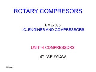
- 1. ROTARY COMPRESORS EME-505 I.C..ENGINES AND COMPRESSORS UNIT -4 COMPRESSORS BY: V.K.YADAV 20-May-21
- 2. ROTARY COMPRESORS CLASSIFICATION POSITIVE DISCPLACEMENT 1. ROOTS BLOWER 2. VANE COMPRESSORS 3. SCREW COMPRESSORS STEADY FLOW COMPRESSORS 1. CENTRIFUGAL COMPRESSORS 2. AXIAL FLOW COMPRESSORS 20-May-21
- 3. RECIPROCATING AND ROTARY COMPRESORS COMPARISON RECIPROCATING 1. PRESSURE UPTO 1000 BAR 2. VOLUME FLOW RATE 3O m3/min 3. SLOW SPEEDS ROTARY 1. PRESSURE UPTO 10 BAR BY MULTISTGE MAX 40 BAR 1. VOLUME FLOW RATE 1200 TO 4200 m3/min 2. HIGH SPEEDS 3000 RPM 20-May-21
- 4. POSITIVE DISCPLACEMENT 1. ROOTS BLOWER/ VANE /SCREW COMPRESSORS PRESSURE UPTO 4 BAR VOLUME FLOW RATE 0.5 TO 1500 m3/min 2. CENTRIFUGAL COMPRESSORS PRESSURE RATIO 4:1 VOLUME FLOW RATE 15 TO 1200 m3/min 3. AXIAL COMPRESSORS per stage compression ratio = 1.2 to 1.3 No. of stages = 8 to 20 Total compression ratio = 20:1 Discharge pressure = 400 bar Volume flow rate = 1200 m3/min to 42000m3/min 20-May-21
- 5. ROOTS BLOWER • The Roots type supercharger or Roots blower is a positive displacement lobe pump which operates by pumping a fluid with a pair of meshing lobes not unlike a set of stretched gears. Fluid is trapped in pockets surrounding the lobes and carried from the intake side to the exhaust. It is frequently used as a supercharger in engines, where it is driven directly from the engine's crankshaft via a belt or, in a two-stroke diesel engine, by spur gears. 20-May-21
- 8. ROOTS BLOWER ANALYSIS • Work required to drive the root blower with two lobes per revolution • W = V (P2-P1) Note: V= 4V for 2 lobe rotor and 6V for 3 lobe rotor • Volume of air compressed per minute (Va) = 4V*N [ for 2 lobe] Where N = speed of blower in RPM - ACTAUL POWER REQUIRED TO COMPRESS Va AIR in m3/min = Pa = Va (P2-P1) - IDEAL POWER REQUIRED TO COMPRESS Va AIR in m3/min = Pi = (γ/ γ-1) P1 Va [(p2/P1)(γ-1/ γ) - 1] (The same relation we’ve derived for reciprocating compressor in class ) - Root Efficiency = Ideal Power/Actual Power 20-May-21
- 9. Root Blower Efficiency - Root Efficiency = Ideal Power/Actual Power = (γ/ γ-1) P1 Va [(p2/P1)(γ-1/ γ) - 1] Va(P2-P1) OR ROOT EFFICIENCY = (γ/ γ-1) [(rp) )(γ-1/ γ) - 1] [rp-1] Where rp is the pressure ratio 20-May-21
- 10. VANE BLOWER • Mechanism: • The rotor is bias rotated (as the follow diagram) with the vane going in and out inside the slots. The vane are compelled to attach the inside surface of casing, so that air is absorbed from inlet and compressed out to the outlet Applications: * Wastewater treatment * Air transportation * Fish breeding aeration * Dust collection * Vacuum packing * Vacuum absorption 20-May-21
- 12. VANE BLOWER ANALYSIS 1 2 c P1 Pc P2 P V Pressure rise due to back flow of air Pressure rise due to internal compression Total pressure rise = Internal compression pressure rise + Back flow W = W1-c + Wc-2 W = (γ/ γ-1) P1 V1 [(Pc/P1)(γ-1/ γ) - 1] + Vc (P2-PC) Also P1V1γ = Pc Vc γ So, W = (γ/ γ-1) P1 V1 [(Pc/P1)(γ-1/ γ) - 1] + (P1/Pc)(1/ γ) V1 (P2-Pc) 20-May-21
- 15. Steady flow compressors 1. centrifugal compressor The centrifugal air compressor is a dynamic compressor which depends on a rotating impeller to compress the air In order to do this efficiently, centrifugal compressors must rotate at higher speeds than the other types of compressors These types of compressors are designed for higher capacity because flow through the compressor is continuous and oil free by design 20-May-21
- 16. 20-May-21
- 17. Centrifugal compressors consist of three main parts, as shown in Figure •The first is a rotating impeller, which imparts work to the gas by increasing its angular momentum. The fluid static pressure and absolute velocity (stationary frame of reference) increase through the impeller passage. •The second component is the diffuser section, often with vanes to increase the effectiveness. The diffuser converts the kinetic energy into the static pressure by decelerating the fluid. 20-May-21
- 18. • The third and final component is a volute or collector, used for collecting the gas from diffuser and delivering to the outlet pipe. A volute has two functions: collection and diffusion. • The volute must collect and transport the fluid to the downstream system. It also raises the static pressure by converting kinetic energy (ρu2) to potential energy (static pressure). • The latter function has performance benefits, as the discharge pressure is increased. 20-May-21
- 19. • Impeller rotates around 3000 rpm and produce centrifugal head which causes air to flow from surrounding to axially inside the impeller eye • The air flows radially outwards into the impeller blade • When air flow from impeller eye to tip of impeller blades, there is an increase in pressure and temperature of air due to increased momentum CENTRIFUGAL COMPRESSOR WORKING 20-May-21
- 20. • Diffuser blades provide an increased area of passage to the air which is passing outward due to which K.E of air leaving the impeller is reduced and its pressure energy in increased. • Due to increased area of volute casing the pressure further rises in casing CENTRIFUGAL COMPRESSOR WORKING 20-May-21
- 21. Figure : Centrifugal compressor layout. (a) A cross-sectional view, showing the impeller followed by a vaned diffuser, and a volute. (b) An isometric view of the package. 20-May-21
- 23. Examples of Application • Vaned diffuser for centrifugal compressor 20-May-21
- 24. 20-May-21
- 27. AXIAL FLOW COMPRESSOR Air Flow – parallel to compressor axis Fixed blade receive high velocity gas from preceding rotor blade and directs the flow to the succeeding rows of rotor blades. The gas space is restricted as staging progresses by decreasing the radial distance between the rotor drum and the casing and also by shortening the blades due to reduction in volume. Blades – made of aerofoil section to reduce friction Pr ratio per stage = 1.06 to 1.2 No. of stages used around 5 to 14 Ultimate pressure ratio = 10:1 Flow rate around 30000 m3/min 20-May-21