SlideShare ist ein Scribd-Unternehmen logo
1 von 41
CARBURETOR
……the heart of the petrol engine….
UNIT-2 SI ENGINE FUEL SUPPLY SYSTEM
BY
S K Singh
Centre for Energy Studies
IIT Delhi
20-May-21
The 4-Stroke SI Engine
(Review)
• Strokes
– Intake:
– Compression:
– Power:
– Exhaust:
High Performance SI Engine Application
(Electronic fuel injector)
The 2-Stroke Engine (Review)
20-May-21
2 Stroke engines
Typical S.I. Engine Fuel supply System
Fuel Tank
Fuel Pump
Fuel
Filters
Carburetor
Or Single
Point Throttle
Body Housing
Fuel Injector or
Carburetor
Venturi
Fuel Not
used is
returned to
the fuel tank
Inlet Manifold
Engine Combustion
Chamber
Fuel Pressure
Regulator
EFI Only
20-May-21
Engine Fuel System (SI) Components
 Fuel Tank (Petrol reservoir) – normally positioned in the rear area,
either under the floor pan for estate cars or over the rear axle for
saloons, the latter being a safer position.
 Made from pressed steel and coated inside to prevent corrosion, or a
synthetic rubber compound or flame resistant plastic.
 Inside the fuel tank is normally located the fuel gauge sender unit
and electrically driven fuel pump with a primary filter in a combined
module.
 Internal fuel tank baffles are used to prevent fuel surge. The fuel tank
is pressurised to about 2 psi to prevent fuel vaporization and
pollution. The fuel tank is vented through its own venting system and
the engine managements emission control systems again to control
pollution.
 Fuel pipes – These can be made from steel or plastic and are
secured by clips at several points along the underside of the vehicle.
To allow for engine movement and vibration, rubber hoses connect
the pipes to the engine. Later fuel pipes use special connectors
which require special tools to disconnect the pipes.
20-May-21
Engine Fuel System (SI Petrol) contd..
 Fuel Filters – to prevent dirt and dust entering the fuel pump –
fitted on suction side
 On the pressure side of the pump a secondary filter is used, this is
a much finer filter in that it prevents very small particles of dirt
reaching the carburettor or fuel injection equipment. It should be
renewed at the correct service interval as recommended by the
manufacturer.
 Air Filters – Air cleaners and silencers are fitted to all modern
vehicles. Its most important function is to prevent dust and
abrasive particles from entering the engine and causing rapid
wear. Air filters are designed to give sufficient filtered air, to obtain
maximum engine power. The air filter must be changed at the
manufactures recommended service interval.
 Fuel Pump – this supplies fuel under high pressure to the fuel
injection system, or under low pressure to a carburetor.
 Carburetor – this is a device which atomizes the fuel and mixes it
which the correct amount of air, this device has now been
superseded by modern electronic fuel injection.
PROPERTIES OF AIR+PETROL MIXTURE IN PETROL
ENGINES
MIXTURE REQUIREMENTS IN PETROL ENGINES
Petrol engines- quantitatively governed – i.e. amount of A/F mixture
is changed with varying conditions of engines
1. for starting and warm up
Rich mixture A/F ratio 3:1 to 1.5 :1
2. Idling and part load [20% of maximum power]
Rich mixture 12.5 :1
Throttle nearly closed
Less air availability
suction pressure low and exhaust pressure high
so rich mixture for small instant of time may be burnt
3. Normal engine operation [20% to 75% of maximum power]
Lean mixture 16 :1 to 17:1
4. Maximum power output [100% of rated power]
14.5 to 15:1
20-May-21
Petrol
Conventional Carburetor System
20-May-21
Petrol
Conventional Carburetor System contd..
 Float chamber (function) – to set and maintain the fuel level within
the carburettor, and to control the supply fuel to the carburettor
venturi.
 Operation – when air passes through the venturi due to the
engines induction strokes, it creates a depression (suction),
around the fuel spray outlet.
 Atmospheric pressure is acting on the fuel in the float chamber,
the difference in theses pressures causes the fuel to flow from the
float chamber, through the jet and into the stream.
 This causes the petrol to mix with the air rushing in to form a
combustible mixture.
 The required air fuel ratio can be obtained by using a jet size
which allows the correct amount of fuel to flow for the amount
of air passing through it.
20-May-21
Petrol
Operation of the Venturi
The Choke Valve is used
to provide a rich air/fuel
ratio for cold starting
Choke
Valve
closed
The Float Chamber
The Throttle Valve controls the
amount of air fuel mixture entering
the engine and therefore engine
power
The Simple
Carburetor
20-May-21
20-May-21
20-May-21
TYPES OF CARBURETTORS
(a) Up draught (b) Horizontal draught (c) Down draught
20-May-21
SIMPLE OR ELEMENTARY CARBURETTOR
UP DRAUGHT TYPE
SIMPLE CARBURETTOR FEATURES
• The air passing through the venturi increases in velocity and pressure in the
venturi throat decreases.
• From the float chamber fuel is fed to the discharge jet, the tip of which is
located in the throat of the venturi
• Pressure in float chamber is atmospheric and in discharge jet is vacuum , a
pressure depression (carburettor depression) exist between them, which
causes discharge of fuel into air stream and the rate of flow is controlled or
metered by the size of the smallest section in the fuel passage.
• This is provided by the discharge jet and the size of the jet is chosen
empirically to give the required engine performance.
• As the throttle is closed less air flows through the venturi tube and less is
the quantity of the air fuel mixture delivered hence less power developed
by engine.
• As throttle is opened more air flows through the choke tube and the power
of the engine increases
20-May-21
LIMITATIONS OF SIMPLE CARBURETTOR
• Provide increasing richness as the engine speed and air
flow increases with full throttle because the density of air
tends to decrease as the air flow rate increases
• Provides too lean mixtures at low speeds at part open
throttle.
• SO THERE IS NEED TO DEVELOP A COMPLETE
CARBURETTOR THAT OVERCOME THE
DEFICIENCIES OF SIMPLE CARBURETTOR
20-May-21
CIRCUITS OF A COMPLETE CARBURETTOR
1- MAIN METERING CIRCUIT
- Supply nearly constant air/fuel
ratio over a wide range of
speeds and loads
- Mixture corresponds to best
economy at full throttle(15.6:1)
- Uses compensating jet that
allows increasing flow of air
through the fuel passage as
the mixture flow increases
20-May-21
-Uses a tapered metering pin
-Uses an auxiliary air valve (Air bleed
jet) that automatically admits
additional air as mixture flow
increases
COMPLETE CARBURETTOR
2- IDLING CIRCUIT
• A/F required 12:1 or 12.5:1
• Consist of small fuel line from
float chamber to a point a little
on the engine side of the
throttle.
• Consist of a fixed fuel orifice
• When throttle closed, the full
manifold suction operates on
the outlet to this jet
• Fuel is lifted by the additional
height upto discharge point.
• As throttle opened, main jet
takes over and dile jet
becomes ineffective
IDLING JET
20-May-21
COMPLETE CARBURETTOR
3- POWER ENRICHMENT OR ECONOMISER CIRCUIT
• Maximum power range 75% to
100% so A/f required 13.1:1
• Meter rod provides a large
orifice opening to the main jet
as the throttle is opened
beyond a certain point
• The rod may be tapered or
stepped
METER ROD ECONOMISER
20-May-21
COMPLETE CARBURETTOR
4- ACCLERATION PUMP SYSTEM CIRCUIT
provided
20-May-21
COMPLETE CARBURETTOR
4- ACCLERATION PUMP SYSTEM CIRCUIT sketch
20-May-21
COMPLETE CARBURETTOR
4- ACCLERATION PUMP SYSTEM CIRCUIT sketch
COMPLETE CARBURETTOR
5- CHOKE CIRCUIT FOR INITIAL STARTING
• During cold starting period at low
cranking speed and before the
engine has warmed up, a mixture
much richer than usual mixtures
(almost 5 to 10 times more fuel)
A/F of 1.5:1 to 3:1 must be
supplied simply because a large
fraction of the fuel will remain
liquid even in the cylinder and only
the vapor fraction can provide a
combustible mixture with the air.
• So choke is used which is simply
butterfly type valve and it cut offs
the air supply
NOW LETS DISCUSS THE PRACTICAL
CARBURETTORS OF DIFFERENT MAKES
FITTED WITH DIFFERENT CIRCUITS IN SINGLE
UNIT
20-May-21
MAKES OF CARBURETTORS
1- SOLEX CARBURETTOR
(Constant choke type carburettor)
20-May-21
1
SOLEX CARBURETTOR WORKING
• Ease of starting, good performance and reliable
• Made in various models and fiat and standard cars and Wiley jeeps
• Unique feature- bi starter for cold starting
Stand pipe in the middle of the choke tube or venturi
20-May-21
SOLEX CARBURETTOR WORKING
(iii) Idling and slow running circuit:
from lower part of the well of the emulsion system a hole leads off to
the pilot jet(13). At idling throttle is closed and engine suction is
applied to the petrol jet. Fuel is drawn and mixed with small amount
of air admitted through the small pilot air bleed orifice (14) and forms
an emulsion which is conveyed down the vertical channel and
discharged into the throttle body past the idling volume control
screw(15)
Bi starter is useful for cold starting
SOLEX CARBURETTOR WORKING
(iv) Acceleration circuit
• A diaphragm type acceleration pump is provided
• It provide extra fuel needed for acceleration through
pump injector (18)
• Pump lever is connected to the accelerator so that when
the pedal is pressed the lever moves towards left
pressing the membrane towards left thus forcing the
petrol through pump jet (20) and injector(18).
• When the pedal is left free , the lever moves the
diaphragm back towards right creating vacuum towards
left which opens the pump inlet valve (21) and thus
admits the petrol from chamber into the pump
20-May-21
MAKES OF CARBURETTORS
2- CARTER CARBURETTOR (American Make )
[constant choke- down draught type carburettor] Multiple jet, plain tube type
Used in Jeeps
20-May-21
choke
CARTER CARBURETTOR WORKING
20-May-21
CARTER CARBURETTOR WORKING
(i) Starting circuit
• Choke valve (2) of butterfly type is provided in air circuit for starting. One
half of the choke valve is spring controlled and the valve is hinged at the
centre
• When engine is fully choked entire engine suction is applied at the main
nozzle, which then delivers fuel.
(ii) Idling and low speed circuit
Throttle valve(8) almost closed. entire engine suction is applied at the idle
port(9).
Petrol is drawn through idle feed jet(10) and air through first by pass(11)
and a rich idle mixture is supplied.
In low speed operation throttle valve is opened further. The main nozzle
also starts supplying the fuel. At this stage fuel is supplied both by the
main venturi and the low speed port (12)
(iii) Acceleration pump circuit
The pump plunger is connected to accelerator pedal by throttle control rod
(16). When throttle opened by accelerator, pump is actuated and small
quantity of petrol is spurted into the choke type by by a jet (17). Releasing
the accelerator pedal causes the pump piston to move up, thereby sucking
fuel from the float chamber for next operation.
Hence the function of the accelerator pump is only to provide an extra
spurt of fuel during acceleration to avoid flat spot.
20-May-21
MAKES OF CARBURETTORS
3- SU CARBURETTOR
[constant vacuum type carburettor] used in many British cars and Hindustan Ambassdor car
1. Fuel jet sleeve
2. Tapered metering needle
3. Choke piston or piston assembly
4. Throttle valve
5. Suction disk
6. Suction chamber
7. Suction hole
8. Atmospheric hole
9. Light spring
10. Petrol jet orifice
11. Float chamber connection
12. Oil dashpot
13. Piston guide rod
14. Small Piston
15. Oil cap nut
15
SU CARBURETTOR WORKING
- As we have studied that most of the carburettors are of constant choke
type carburettors (examples are Solex, zenith and carter) but the SU
carburettor is of constant vacuum or variable choke type carburettor.
- The SU carburettor has a conventional float chamber which feeds fuel into
a vertical channel in which jet sleeve vale(1) is located. The sleeve bears
a number of holes in its sides, so that the fuel will enter the sleeve and
thus stand at the same level as in the float chamber.
-
SU CARBURETTOR WORKING
- Due to constant vacuum almost constant air velocity is maintained.
- With the vertical movement of the choke piston the metering
needle also moves up and down concentrically in the petrol jet
orifice (10), thus varying the effective area of the jet. As the piston
rises under increased suction, the tapered needle also moves
upwards and increases the effective jet area, allowing a greater
amount of petrol to flow into the main air stream and vice versa.
Thus approximately constant air fuel ratio is maintained.
- Unique feature of SU carburettor- it has only one jet there is no
separate idling or acceleration pump circuit
- For cold starting a rich mixture is required. This is provided by an
arrangement to lower the jet tube away from the needle by means
the jet lever, thereby enlarging the jet orifice. The lever is operated
from the dash board in the car.
- There is also an arrangement providing a slightly rich mixture on
acceleration. For this purpose an oil dashpot(12) is provided in the
upper part of the hollow piston guide rod(13). In this a small
piston(14) is suspended by a rod from the oil cap nut(15).
- USES: SU carburettor is used in many British cars and was used in
Hindustan Ambassdor car
20-May-21
References:
1. Internal combustion engines by M.L.Mathur and R.P.Sharma
2. Internal combustion engines by V.Ganeshan
20-May-21

Weitere ähnliche Inhalte

Was ist angesagt?

Cooling system for ic engines
Cooling system for ic engines Cooling system for ic engines
Cooling system for ic engines
sgrsoni45
 

Was ist angesagt? (20)

1. clutch
1. clutch1. clutch
1. clutch
 
Diesel fuel injection system
Diesel fuel injection systemDiesel fuel injection system
Diesel fuel injection system
 
Gear box
Gear boxGear box
Gear box
 
Clutches ( Single Plate and Multi Plate)
Clutches ( Single Plate and Multi Plate) Clutches ( Single Plate and Multi Plate)
Clutches ( Single Plate and Multi Plate)
 
COMMON RAIL DIESEL INJECTION (CRDI;CRDe)
COMMON RAIL DIESEL INJECTION (CRDI;CRDe)COMMON RAIL DIESEL INJECTION (CRDI;CRDe)
COMMON RAIL DIESEL INJECTION (CRDI;CRDe)
 
Steering System
Steering SystemSteering System
Steering System
 
Torque converter
Torque converterTorque converter
Torque converter
 
Electronic Fuel Injection System
Electronic Fuel Injection SystemElectronic Fuel Injection System
Electronic Fuel Injection System
 
Components and working of carburettor
Components and working of carburettorComponents and working of carburettor
Components and working of carburettor
 
Unit 1 automotive engine auxiliary systems
Unit 1 automotive engine auxiliary systemsUnit 1 automotive engine auxiliary systems
Unit 1 automotive engine auxiliary systems
 
Cooling system in Automobiles
Cooling system in AutomobilesCooling system in Automobiles
Cooling system in Automobiles
 
presentation on fuel supply system of SI and CI engines
presentation on fuel supply system of SI and CI enginespresentation on fuel supply system of SI and CI engines
presentation on fuel supply system of SI and CI engines
 
Cooling system for ic engines
Cooling system for ic engines Cooling system for ic engines
Cooling system for ic engines
 
Lubrication System - IC Engine - Unit-III
Lubrication System - IC Engine - Unit-IIILubrication System - IC Engine - Unit-III
Lubrication System - IC Engine - Unit-III
 
Exhaust system of an engine
Exhaust system of an engineExhaust system of an engine
Exhaust system of an engine
 
JA304 chapter 1
JA304 chapter 1JA304 chapter 1
JA304 chapter 1
 
Fuel Injection Systems
Fuel Injection SystemsFuel Injection Systems
Fuel Injection Systems
 
Day 07 Governor and Ignition System
Day 07 Governor and Ignition SystemDay 07 Governor and Ignition System
Day 07 Governor and Ignition System
 
Fuel feed system for petrol engine
Fuel feed system for petrol engineFuel feed system for petrol engine
Fuel feed system for petrol engine
 
presentation of fuel injection pumps
presentation of fuel injection pumpspresentation of fuel injection pumps
presentation of fuel injection pumps
 

Ähnlich wie Carburetors

Chapter 22
Chapter 22Chapter 22
Chapter 22
mcfalltj
 

Ähnlich wie Carburetors (20)

Carburettor
CarburettorCarburettor
Carburettor
 
Carburetion
CarburetionCarburetion
Carburetion
 
2 fuel-supply-systems
2 fuel-supply-systems2 fuel-supply-systems
2 fuel-supply-systems
 
Piston Engines: Fuel
Piston Engines: FuelPiston Engines: Fuel
Piston Engines: Fuel
 
UNIT 3 -CHAP 3.pptx
UNIT 3 -CHAP 3.pptxUNIT 3 -CHAP 3.pptx
UNIT 3 -CHAP 3.pptx
 
AUTOMOBILE ENGINEERING
AUTOMOBILE ENGINEERINGAUTOMOBILE ENGINEERING
AUTOMOBILE ENGINEERING
 
Chapter 22
Chapter 22Chapter 22
Chapter 22
 
Carburetor.doc
Carburetor.docCarburetor.doc
Carburetor.doc
 
Automotive fuel System-- Part II.pptx
Automotive fuel System-- Part II.pptxAutomotive fuel System-- Part II.pptx
Automotive fuel System-- Part II.pptx
 
UNIT-II-ENGINE AUXILIARY SYSTEMS &TURBOCHARGER
UNIT-II-ENGINE AUXILIARY SYSTEMS &TURBOCHARGERUNIT-II-ENGINE AUXILIARY SYSTEMS &TURBOCHARGER
UNIT-II-ENGINE AUXILIARY SYSTEMS &TURBOCHARGER
 
Carburetion, injection and supercharging
Carburetion, injection and superchargingCarburetion, injection and supercharging
Carburetion, injection and supercharging
 
TYPES OF CARBURETORS
TYPES OF CARBURETORSTYPES OF CARBURETORS
TYPES OF CARBURETORS
 
Lec 7 ME-439 ICE Lec -7_Turbocharging.pptx
Lec 7 ME-439 ICE Lec -7_Turbocharging.pptxLec 7 ME-439 ICE Lec -7_Turbocharging.pptx
Lec 7 ME-439 ICE Lec -7_Turbocharging.pptx
 
Turbocharging and its off-highway apps.
Turbocharging and its off-highway apps.Turbocharging and its off-highway apps.
Turbocharging and its off-highway apps.
 
IC Engines Fuel Systems PRINCIPLE AND WORKING
IC Engines Fuel Systems PRINCIPLE AND WORKINGIC Engines Fuel Systems PRINCIPLE AND WORKING
IC Engines Fuel Systems PRINCIPLE AND WORKING
 
Automobile unit 2 carburetor
Automobile unit  2 carburetorAutomobile unit  2 carburetor
Automobile unit 2 carburetor
 
Automobile Engineering Unit 2 - Anna university
Automobile Engineering Unit 2 - Anna universityAutomobile Engineering Unit 2 - Anna university
Automobile Engineering Unit 2 - Anna university
 
Basic Carburetor Design
Basic Carburetor DesignBasic Carburetor Design
Basic Carburetor Design
 
carburetion
carburetioncarburetion
carburetion
 
Fuel feed system in petrol engine ppt
Fuel feed system in petrol engine pptFuel feed system in petrol engine ppt
Fuel feed system in petrol engine ppt
 

Mehr von INDIAN INSTITUTE OF TECHNOLOGY Delhi

Mehr von INDIAN INSTITUTE OF TECHNOLOGY Delhi (20)

Intro cad cam
Intro cad camIntro cad cam
Intro cad cam
 
Energy economics
Energy economicsEnergy economics
Energy economics
 
Economic theory of demand
Economic theory of demandEconomic theory of demand
Economic theory of demand
 
Concepts of economic attributes part 2
Concepts of economic attributes part 2Concepts of economic attributes part 2
Concepts of economic attributes part 2
 
Concepts of economic attributes part 1
Concepts of economic attributes part 1Concepts of economic attributes part 1
Concepts of economic attributes part 1
 
Biorefinery
BiorefineryBiorefinery
Biorefinery
 
Biomass to biofuel
Biomass to biofuelBiomass to biofuel
Biomass to biofuel
 
Biomass gasification
Biomass gasificationBiomass gasification
Biomass gasification
 
Biomass combustion device
Biomass combustion deviceBiomass combustion device
Biomass combustion device
 
Biomass characterization
Biomass characterizationBiomass characterization
Biomass characterization
 
Biogas purifications
Biogas purificationsBiogas purifications
Biogas purifications
 
Bioenergy policies and future stratgies
Bioenergy policies and future stratgiesBioenergy policies and future stratgies
Bioenergy policies and future stratgies
 
Bio cng
Bio cngBio cng
Bio cng
 
Biochemical conversion process of biomass
Biochemical conversion process of biomassBiochemical conversion process of biomass
Biochemical conversion process of biomass
 
Bio mass availability and types
Bio mass availability and typesBio mass availability and types
Bio mass availability and types
 
Agro residues and their utilization
Agro residues and their utilizationAgro residues and their utilization
Agro residues and their utilization
 
Renewable energy arun k tripathi
Renewable energy arun k tripathiRenewable energy arun k tripathi
Renewable energy arun k tripathi
 
Usage of biomass for energy
Usage of biomass for energyUsage of biomass for energy
Usage of biomass for energy
 
Carburetor air-fuel ratio calculations
Carburetor air-fuel ratio calculationsCarburetor air-fuel ratio calculations
Carburetor air-fuel ratio calculations
 
4 stroke engine working principle
4 stroke engine working principle4 stroke engine working principle
4 stroke engine working principle
 

Kürzlich hochgeladen

1_Introduction + EAM Vocabulary + how to navigate in EAM.pdf
1_Introduction + EAM Vocabulary + how to navigate in EAM.pdf1_Introduction + EAM Vocabulary + how to navigate in EAM.pdf
1_Introduction + EAM Vocabulary + how to navigate in EAM.pdf
AldoGarca30
 
Verification of thevenin's theorem for BEEE Lab (1).pptx
Verification of thevenin's theorem for BEEE Lab (1).pptxVerification of thevenin's theorem for BEEE Lab (1).pptx
Verification of thevenin's theorem for BEEE Lab (1).pptx
chumtiyababu
 
Call Girls in South Ex (delhi) call me [🔝9953056974🔝] escort service 24X7
Call Girls in South Ex (delhi) call me [🔝9953056974🔝] escort service 24X7Call Girls in South Ex (delhi) call me [🔝9953056974🔝] escort service 24X7
Call Girls in South Ex (delhi) call me [🔝9953056974🔝] escort service 24X7
9953056974 Low Rate Call Girls In Saket, Delhi NCR
 
"Lesotho Leaps Forward: A Chronicle of Transformative Developments"
"Lesotho Leaps Forward: A Chronicle of Transformative Developments""Lesotho Leaps Forward: A Chronicle of Transformative Developments"
"Lesotho Leaps Forward: A Chronicle of Transformative Developments"
mphochane1998
 
Cara Menggugurkan Sperma Yang Masuk Rahim Biyar Tidak Hamil
Cara Menggugurkan Sperma Yang Masuk Rahim Biyar Tidak HamilCara Menggugurkan Sperma Yang Masuk Rahim Biyar Tidak Hamil
Cara Menggugurkan Sperma Yang Masuk Rahim Biyar Tidak Hamil
Cara Menggugurkan Kandungan 087776558899
 
DeepFakes presentation : brief idea of DeepFakes
DeepFakes presentation : brief idea of DeepFakesDeepFakes presentation : brief idea of DeepFakes
DeepFakes presentation : brief idea of DeepFakes
MayuraD1
 

Kürzlich hochgeladen (20)

Block diagram reduction techniques in control systems.ppt
Block diagram reduction techniques in control systems.pptBlock diagram reduction techniques in control systems.ppt
Block diagram reduction techniques in control systems.ppt
 
1_Introduction + EAM Vocabulary + how to navigate in EAM.pdf
1_Introduction + EAM Vocabulary + how to navigate in EAM.pdf1_Introduction + EAM Vocabulary + how to navigate in EAM.pdf
1_Introduction + EAM Vocabulary + how to navigate in EAM.pdf
 
kiln thermal load.pptx kiln tgermal load
kiln thermal load.pptx kiln tgermal loadkiln thermal load.pptx kiln tgermal load
kiln thermal load.pptx kiln tgermal load
 
Double Revolving field theory-how the rotor develops torque
Double Revolving field theory-how the rotor develops torqueDouble Revolving field theory-how the rotor develops torque
Double Revolving field theory-how the rotor develops torque
 
Bhubaneswar🌹Call Girls Bhubaneswar ❤Komal 9777949614 💟 Full Trusted CALL GIRL...
Bhubaneswar🌹Call Girls Bhubaneswar ❤Komal 9777949614 💟 Full Trusted CALL GIRL...Bhubaneswar🌹Call Girls Bhubaneswar ❤Komal 9777949614 💟 Full Trusted CALL GIRL...
Bhubaneswar🌹Call Girls Bhubaneswar ❤Komal 9777949614 💟 Full Trusted CALL GIRL...
 
Verification of thevenin's theorem for BEEE Lab (1).pptx
Verification of thevenin's theorem for BEEE Lab (1).pptxVerification of thevenin's theorem for BEEE Lab (1).pptx
Verification of thevenin's theorem for BEEE Lab (1).pptx
 
Work-Permit-Receiver-in-Saudi-Aramco.pptx
Work-Permit-Receiver-in-Saudi-Aramco.pptxWork-Permit-Receiver-in-Saudi-Aramco.pptx
Work-Permit-Receiver-in-Saudi-Aramco.pptx
 
Call Girls in South Ex (delhi) call me [🔝9953056974🔝] escort service 24X7
Call Girls in South Ex (delhi) call me [🔝9953056974🔝] escort service 24X7Call Girls in South Ex (delhi) call me [🔝9953056974🔝] escort service 24X7
Call Girls in South Ex (delhi) call me [🔝9953056974🔝] escort service 24X7
 
DC MACHINE-Motoring and generation, Armature circuit equation
DC MACHINE-Motoring and generation, Armature circuit equationDC MACHINE-Motoring and generation, Armature circuit equation
DC MACHINE-Motoring and generation, Armature circuit equation
 
Thermal Engineering-R & A / C - unit - V
Thermal Engineering-R & A / C - unit - VThermal Engineering-R & A / C - unit - V
Thermal Engineering-R & A / C - unit - V
 
FEA Based Level 3 Assessment of Deformed Tanks with Fluid Induced Loads
FEA Based Level 3 Assessment of Deformed Tanks with Fluid Induced LoadsFEA Based Level 3 Assessment of Deformed Tanks with Fluid Induced Loads
FEA Based Level 3 Assessment of Deformed Tanks with Fluid Induced Loads
 
Thermal Engineering -unit - III & IV.ppt
Thermal Engineering -unit - III & IV.pptThermal Engineering -unit - III & IV.ppt
Thermal Engineering -unit - III & IV.ppt
 
"Lesotho Leaps Forward: A Chronicle of Transformative Developments"
"Lesotho Leaps Forward: A Chronicle of Transformative Developments""Lesotho Leaps Forward: A Chronicle of Transformative Developments"
"Lesotho Leaps Forward: A Chronicle of Transformative Developments"
 
Cara Menggugurkan Sperma Yang Masuk Rahim Biyar Tidak Hamil
Cara Menggugurkan Sperma Yang Masuk Rahim Biyar Tidak HamilCara Menggugurkan Sperma Yang Masuk Rahim Biyar Tidak Hamil
Cara Menggugurkan Sperma Yang Masuk Rahim Biyar Tidak Hamil
 
S1S2 B.Arch MGU - HOA1&2 Module 3 -Temple Architecture of Kerala.pptx
S1S2 B.Arch MGU - HOA1&2 Module 3 -Temple Architecture of Kerala.pptxS1S2 B.Arch MGU - HOA1&2 Module 3 -Temple Architecture of Kerala.pptx
S1S2 B.Arch MGU - HOA1&2 Module 3 -Temple Architecture of Kerala.pptx
 
DeepFakes presentation : brief idea of DeepFakes
DeepFakes presentation : brief idea of DeepFakesDeepFakes presentation : brief idea of DeepFakes
DeepFakes presentation : brief idea of DeepFakes
 
HOA1&2 - Module 3 - PREHISTORCI ARCHITECTURE OF KERALA.pptx
HOA1&2 - Module 3 - PREHISTORCI ARCHITECTURE OF KERALA.pptxHOA1&2 - Module 3 - PREHISTORCI ARCHITECTURE OF KERALA.pptx
HOA1&2 - Module 3 - PREHISTORCI ARCHITECTURE OF KERALA.pptx
 
Computer Networks Basics of Network Devices
Computer Networks  Basics of Network DevicesComputer Networks  Basics of Network Devices
Computer Networks Basics of Network Devices
 
Employee leave management system project.
Employee leave management system project.Employee leave management system project.
Employee leave management system project.
 
PE 459 LECTURE 2- natural gas basic concepts and properties
PE 459 LECTURE 2- natural gas basic concepts and propertiesPE 459 LECTURE 2- natural gas basic concepts and properties
PE 459 LECTURE 2- natural gas basic concepts and properties
 

Carburetors

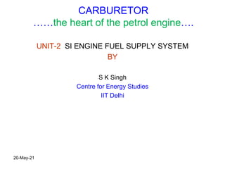
  • 1. CARBURETOR ……the heart of the petrol engine…. UNIT-2 SI ENGINE FUEL SUPPLY SYSTEM BY S K Singh Centre for Energy Studies IIT Delhi 20-May-21
  • 2. The 4-Stroke SI Engine (Review) • Strokes – Intake: – Compression: – Power: – Exhaust:
  • 3. High Performance SI Engine Application (Electronic fuel injector)
  • 5.
  • 7.
  • 8. Typical S.I. Engine Fuel supply System Fuel Tank Fuel Pump Fuel Filters Carburetor Or Single Point Throttle Body Housing Fuel Injector or Carburetor Venturi Fuel Not used is returned to the fuel tank Inlet Manifold Engine Combustion Chamber Fuel Pressure Regulator EFI Only 20-May-21
  • 9. Engine Fuel System (SI) Components  Fuel Tank (Petrol reservoir) – normally positioned in the rear area, either under the floor pan for estate cars or over the rear axle for saloons, the latter being a safer position.  Made from pressed steel and coated inside to prevent corrosion, or a synthetic rubber compound or flame resistant plastic.  Inside the fuel tank is normally located the fuel gauge sender unit and electrically driven fuel pump with a primary filter in a combined module.  Internal fuel tank baffles are used to prevent fuel surge. The fuel tank is pressurised to about 2 psi to prevent fuel vaporization and pollution. The fuel tank is vented through its own venting system and the engine managements emission control systems again to control pollution.  Fuel pipes – These can be made from steel or plastic and are secured by clips at several points along the underside of the vehicle. To allow for engine movement and vibration, rubber hoses connect the pipes to the engine. Later fuel pipes use special connectors which require special tools to disconnect the pipes. 20-May-21
  • 10. Engine Fuel System (SI Petrol) contd..  Fuel Filters – to prevent dirt and dust entering the fuel pump – fitted on suction side  On the pressure side of the pump a secondary filter is used, this is a much finer filter in that it prevents very small particles of dirt reaching the carburettor or fuel injection equipment. It should be renewed at the correct service interval as recommended by the manufacturer.  Air Filters – Air cleaners and silencers are fitted to all modern vehicles. Its most important function is to prevent dust and abrasive particles from entering the engine and causing rapid wear. Air filters are designed to give sufficient filtered air, to obtain maximum engine power. The air filter must be changed at the manufactures recommended service interval.  Fuel Pump – this supplies fuel under high pressure to the fuel injection system, or under low pressure to a carburetor.  Carburetor – this is a device which atomizes the fuel and mixes it which the correct amount of air, this device has now been superseded by modern electronic fuel injection.
  • 11. PROPERTIES OF AIR+PETROL MIXTURE IN PETROL ENGINES
  • 12. MIXTURE REQUIREMENTS IN PETROL ENGINES Petrol engines- quantitatively governed – i.e. amount of A/F mixture is changed with varying conditions of engines 1. for starting and warm up Rich mixture A/F ratio 3:1 to 1.5 :1 2. Idling and part load [20% of maximum power] Rich mixture 12.5 :1 Throttle nearly closed Less air availability suction pressure low and exhaust pressure high so rich mixture for small instant of time may be burnt 3. Normal engine operation [20% to 75% of maximum power] Lean mixture 16 :1 to 17:1 4. Maximum power output [100% of rated power] 14.5 to 15:1 20-May-21
  • 14. Conventional Carburetor System contd..  Float chamber (function) – to set and maintain the fuel level within the carburettor, and to control the supply fuel to the carburettor venturi.  Operation – when air passes through the venturi due to the engines induction strokes, it creates a depression (suction), around the fuel spray outlet.  Atmospheric pressure is acting on the fuel in the float chamber, the difference in theses pressures causes the fuel to flow from the float chamber, through the jet and into the stream.  This causes the petrol to mix with the air rushing in to form a combustible mixture.  The required air fuel ratio can be obtained by using a jet size which allows the correct amount of fuel to flow for the amount of air passing through it. 20-May-21
  • 15. Petrol Operation of the Venturi The Choke Valve is used to provide a rich air/fuel ratio for cold starting Choke Valve closed The Float Chamber The Throttle Valve controls the amount of air fuel mixture entering the engine and therefore engine power The Simple Carburetor
  • 19. TYPES OF CARBURETTORS (a) Up draught (b) Horizontal draught (c) Down draught 20-May-21
  • 20. SIMPLE OR ELEMENTARY CARBURETTOR UP DRAUGHT TYPE
  • 21. SIMPLE CARBURETTOR FEATURES • The air passing through the venturi increases in velocity and pressure in the venturi throat decreases. • From the float chamber fuel is fed to the discharge jet, the tip of which is located in the throat of the venturi • Pressure in float chamber is atmospheric and in discharge jet is vacuum , a pressure depression (carburettor depression) exist between them, which causes discharge of fuel into air stream and the rate of flow is controlled or metered by the size of the smallest section in the fuel passage. • This is provided by the discharge jet and the size of the jet is chosen empirically to give the required engine performance. • As the throttle is closed less air flows through the venturi tube and less is the quantity of the air fuel mixture delivered hence less power developed by engine. • As throttle is opened more air flows through the choke tube and the power of the engine increases 20-May-21
  • 22. LIMITATIONS OF SIMPLE CARBURETTOR • Provide increasing richness as the engine speed and air flow increases with full throttle because the density of air tends to decrease as the air flow rate increases • Provides too lean mixtures at low speeds at part open throttle. • SO THERE IS NEED TO DEVELOP A COMPLETE CARBURETTOR THAT OVERCOME THE DEFICIENCIES OF SIMPLE CARBURETTOR 20-May-21
  • 23. CIRCUITS OF A COMPLETE CARBURETTOR 1- MAIN METERING CIRCUIT - Supply nearly constant air/fuel ratio over a wide range of speeds and loads - Mixture corresponds to best economy at full throttle(15.6:1) - Uses compensating jet that allows increasing flow of air through the fuel passage as the mixture flow increases 20-May-21 -Uses a tapered metering pin -Uses an auxiliary air valve (Air bleed jet) that automatically admits additional air as mixture flow increases
  • 24. COMPLETE CARBURETTOR 2- IDLING CIRCUIT • A/F required 12:1 or 12.5:1 • Consist of small fuel line from float chamber to a point a little on the engine side of the throttle. • Consist of a fixed fuel orifice • When throttle closed, the full manifold suction operates on the outlet to this jet • Fuel is lifted by the additional height upto discharge point. • As throttle opened, main jet takes over and dile jet becomes ineffective IDLING JET 20-May-21
  • 25. COMPLETE CARBURETTOR 3- POWER ENRICHMENT OR ECONOMISER CIRCUIT • Maximum power range 75% to 100% so A/f required 13.1:1 • Meter rod provides a large orifice opening to the main jet as the throttle is opened beyond a certain point • The rod may be tapered or stepped METER ROD ECONOMISER 20-May-21
  • 26. COMPLETE CARBURETTOR 4- ACCLERATION PUMP SYSTEM CIRCUIT provided 20-May-21
  • 27. COMPLETE CARBURETTOR 4- ACCLERATION PUMP SYSTEM CIRCUIT sketch 20-May-21
  • 28. COMPLETE CARBURETTOR 4- ACCLERATION PUMP SYSTEM CIRCUIT sketch
  • 29. COMPLETE CARBURETTOR 5- CHOKE CIRCUIT FOR INITIAL STARTING • During cold starting period at low cranking speed and before the engine has warmed up, a mixture much richer than usual mixtures (almost 5 to 10 times more fuel) A/F of 1.5:1 to 3:1 must be supplied simply because a large fraction of the fuel will remain liquid even in the cylinder and only the vapor fraction can provide a combustible mixture with the air. • So choke is used which is simply butterfly type valve and it cut offs the air supply
  • 30. NOW LETS DISCUSS THE PRACTICAL CARBURETTORS OF DIFFERENT MAKES FITTED WITH DIFFERENT CIRCUITS IN SINGLE UNIT 20-May-21
  • 31. MAKES OF CARBURETTORS 1- SOLEX CARBURETTOR (Constant choke type carburettor) 20-May-21 1
  • 32. SOLEX CARBURETTOR WORKING • Ease of starting, good performance and reliable • Made in various models and fiat and standard cars and Wiley jeeps • Unique feature- bi starter for cold starting Stand pipe in the middle of the choke tube or venturi 20-May-21
  • 33. SOLEX CARBURETTOR WORKING (iii) Idling and slow running circuit: from lower part of the well of the emulsion system a hole leads off to the pilot jet(13). At idling throttle is closed and engine suction is applied to the petrol jet. Fuel is drawn and mixed with small amount of air admitted through the small pilot air bleed orifice (14) and forms an emulsion which is conveyed down the vertical channel and discharged into the throttle body past the idling volume control screw(15) Bi starter is useful for cold starting
  • 34. SOLEX CARBURETTOR WORKING (iv) Acceleration circuit • A diaphragm type acceleration pump is provided • It provide extra fuel needed for acceleration through pump injector (18) • Pump lever is connected to the accelerator so that when the pedal is pressed the lever moves towards left pressing the membrane towards left thus forcing the petrol through pump jet (20) and injector(18). • When the pedal is left free , the lever moves the diaphragm back towards right creating vacuum towards left which opens the pump inlet valve (21) and thus admits the petrol from chamber into the pump 20-May-21
  • 35. MAKES OF CARBURETTORS 2- CARTER CARBURETTOR (American Make ) [constant choke- down draught type carburettor] Multiple jet, plain tube type Used in Jeeps 20-May-21 choke
  • 37. CARTER CARBURETTOR WORKING (i) Starting circuit • Choke valve (2) of butterfly type is provided in air circuit for starting. One half of the choke valve is spring controlled and the valve is hinged at the centre • When engine is fully choked entire engine suction is applied at the main nozzle, which then delivers fuel. (ii) Idling and low speed circuit Throttle valve(8) almost closed. entire engine suction is applied at the idle port(9). Petrol is drawn through idle feed jet(10) and air through first by pass(11) and a rich idle mixture is supplied. In low speed operation throttle valve is opened further. The main nozzle also starts supplying the fuel. At this stage fuel is supplied both by the main venturi and the low speed port (12) (iii) Acceleration pump circuit The pump plunger is connected to accelerator pedal by throttle control rod (16). When throttle opened by accelerator, pump is actuated and small quantity of petrol is spurted into the choke type by by a jet (17). Releasing the accelerator pedal causes the pump piston to move up, thereby sucking fuel from the float chamber for next operation. Hence the function of the accelerator pump is only to provide an extra spurt of fuel during acceleration to avoid flat spot. 20-May-21
  • 38. MAKES OF CARBURETTORS 3- SU CARBURETTOR [constant vacuum type carburettor] used in many British cars and Hindustan Ambassdor car 1. Fuel jet sleeve 2. Tapered metering needle 3. Choke piston or piston assembly 4. Throttle valve 5. Suction disk 6. Suction chamber 7. Suction hole 8. Atmospheric hole 9. Light spring 10. Petrol jet orifice 11. Float chamber connection 12. Oil dashpot 13. Piston guide rod 14. Small Piston 15. Oil cap nut 15
  • 39. SU CARBURETTOR WORKING - As we have studied that most of the carburettors are of constant choke type carburettors (examples are Solex, zenith and carter) but the SU carburettor is of constant vacuum or variable choke type carburettor. - The SU carburettor has a conventional float chamber which feeds fuel into a vertical channel in which jet sleeve vale(1) is located. The sleeve bears a number of holes in its sides, so that the fuel will enter the sleeve and thus stand at the same level as in the float chamber. -
  • 40. SU CARBURETTOR WORKING - Due to constant vacuum almost constant air velocity is maintained. - With the vertical movement of the choke piston the metering needle also moves up and down concentrically in the petrol jet orifice (10), thus varying the effective area of the jet. As the piston rises under increased suction, the tapered needle also moves upwards and increases the effective jet area, allowing a greater amount of petrol to flow into the main air stream and vice versa. Thus approximately constant air fuel ratio is maintained. - Unique feature of SU carburettor- it has only one jet there is no separate idling or acceleration pump circuit - For cold starting a rich mixture is required. This is provided by an arrangement to lower the jet tube away from the needle by means the jet lever, thereby enlarging the jet orifice. The lever is operated from the dash board in the car. - There is also an arrangement providing a slightly rich mixture on acceleration. For this purpose an oil dashpot(12) is provided in the upper part of the hollow piston guide rod(13). In this a small piston(14) is suspended by a rod from the oil cap nut(15). - USES: SU carburettor is used in many British cars and was used in Hindustan Ambassdor car 20-May-21
  • 41. References: 1. Internal combustion engines by M.L.Mathur and R.P.Sharma 2. Internal combustion engines by V.Ganeshan 20-May-21