
Empfohlen
Weitere ähnliche Inhalte
Was ist angesagt?
Was ist angesagt? (20)
Andere mochten auch
Andere mochten auch (10)
Ähnlich wie Presentation on ccna
Ähnlich wie Presentation on ccna (20)
Presentation on ccna
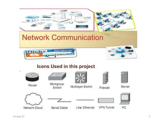
- 1. 14-Aug-15 1 Network Communication Icons Used in this project
- 2. S.No. Contents Page No. 01 Project Title 02 02 Abstract 03 03 VLAN & Routing Algorithm 05 04 Software Requirement Specification 06 05 Software Engg. Model Used 09 06 System Flow Chart / Model/ UML Diagram 17 07 Conclusion 20 08 Future Scope 22 09 References & Bibliography 23 Table of Contents 14-Aug-15 2
- 3. Implementation on VLAN & Routing Algorithm 14-Aug-15 3
- 5. Abstract 14-Aug-15 5 Network is a collection of two or more computers which are connected to each other for sharing resources, media information. Connected computers can share resources which include information's, software's, peripheral devices. VLAN communication experiment is one of the most important teaching difficult points of Computer Network Technology Courses, in the circumstance of lacking of the experiment equipments, traditional experimental teaching method can not fulfill the learning needs of related personnel. However, virtual demonstration experiment generates to solve this problem. In this paper, a design of VLAN communication experiment with virtual demonstration mode is shown. The realization of the practical project both in software and hardware aspects is also presented and its characters and practical values are emphasized. At last, an analysis has been made for several involved factors that exist in this experimental teaching mode. In computer networking, a single layer-2 network may be partitioned to create multiple distinct broadcast domains, which are mutually isolated so that packets can only pass between them via one or more routers; such a domain is referred to as a virtual local area network, virtual LAN or VLAN. This is usually achieved on switch or router devices. Simpler devices only support partitioning on a port level (if at all), so sharing VLANs across devices requires running dedicated cabling for each VLAN. More sophisticated devices can mark packets through tagging, so that a single interconnect (trunk) may be used to transport data for multiple VLANs. Grouping hosts with a common set of requirements regardless of their physical location by VLAN can greatly simplify network design. A VLAN has the same attributes as a physical local area network (LAN), but it allows for end stations to be grouped together more easily even if they are not on the same network switch. VLAN membership can be configured through software instead of physically relocating devices or connections. Most enterprise-level networks today use the concept of virtual LANs. Without VLANs, a switch considers all interfaces on the switch to be in the same broadcast domain. To physically replicate the functions of a VLAN would require a separate, parallel collection of network cables and equipment separate from the primary network. However, unlike physically separate networks, VLANs share bandwidth, so VLAN trunks may require aggregated links and/or quality of service prioritization.
- 6. VLAN & Routing Algorithm 14-Aug-15 6
- 7. Implementing VLANs ØA VLAN allows a network administrator to create groups of logically networked devices that act as if they are on their own independent network, even if they share a common infrastructure with other VLANs. Using VLANs, you can logically segment switched networks based on functions, departments, or project teams. These VLANs allow the network administrator to implement access and security policies to particular groups of users. Virtual-LAN Remember, just because two computers are physically connected to the same switch does not mean that they can communicate. VLAN CONFIGURATION Devices on two separate networks and subnets must communicate via a router (Layer 3) whether or not VLANs are used. VLAN reduce the size of broadcast domain but increases the no of broadcast domain depends on VLAN 14-Aug-15 7
- 8. VLAN Overview Layer 2 connectivity ◦ Logical organizational flexibility ◦ Single broadcast domain ◦ Management ◦ Basic security A VLAN = A Broadcast Domain = Logical Network (Subnet) 14-Aug-15 8
- 9. 14-Aug-15 9
- 10. How to Create a VLAN Switch(config)#vlan ? <1-1005> ISL VLAN IDs 1-1005 Switch(config)#vlan 2 Switch(config-vlan)#name accounts Switch(config)#vlan 3 Switch(config-vlan)#name sales Switch(config-vlan)#do wr How to Assign ports into VLAN Assigning single ports into VLAN:- Switch(config)#interface fastEthernet 0/1 Switch(config-if)#switchport mode access Switch(config-if)#switchport access vlan 2 If you have to assign multiple ports at a time into VLAN:- Switch(config)#interface range fa 0/3 - fa 0/4 Switch(config-if-range)#switchport mode access Switch(config-if-range)#switchport access vlan 3 Switch(config-if-range)#do wr 14-Aug-15 10
- 11. Check VLAN Configuration Switch#show vlan ? brief VTP all VLAN status in brief id VTP VLAN status by VLAN id name VTP VLAN status by VLAN name 14-Aug-15 11
- 12. Verifying the VLAN configuration 14-Aug-15 12
- 13. VLAN TRUNK A trunk is a point-to-point link between one or more Ethernet switch interfaces and another networking device, such as a router or a switch. Ethernet trunks carry the traffic of multiple VLANs over a single link. A VLAN trunk allows you to extend the VLANs across an entire network. Cisco supports IEEE 802.1Q for coordinating trunks on Fast Ethernet and Gigabit Ethernet interfaces. 14-Aug-15 13
- 16. ROUTER Router is an internetworking component, that connects networks which are at different geographical locations. Main function of Router is to filtering, switching, forwarding the packets. Router break the broadcast domain. Router create the Routing table on the basis of IP address and share with the neighbor routers. Router Work on layer 3 of OSI Model. 14-Aug-15 16
- 17. ØWhen the destination is known, static and dynamic routing is done. For unknown destinations, default routing is employed. ØIn dynamic routing, the path is fixed by the protocol. The paths will be changing depending on the length of the path. Always the shortest path is preferred. Static routing is done by the users. These paths are stored in the routing table. Example: Switch/hub Switch/hub E 0 E 0 S 0 S 0 192.168.1.0/24 192.168.2.0/24 192.168.1.150/24 192.168.2.150/24 10.0.0.1/8 10.0.0.2/8 Location A Location B 14-Aug-15 17
- 18. 14-Aug-15 18
- 19. Configurations On R1 router R1(c)#ip route 192.168.30.0 255.255.255.0 192.168.20.2 R1(c)#ip route 192.168.40.0 255.255.255.0 192.168.20.2 R1(c)#ip route 192.168.50.0 255.255.255.0 192.168.20.2 On R2 router R2(c)#ip route 192.168.10.0 255.255.255.0 192.168.20.1 R2(c)#ip route 192.168.50.0 255.255.255.0 192.168.40.2 On R3 Router R3(c)#ip route 192.168.10.0 255.255.255.0 192.168.40.1 R3(c)#ip route 192.168.20.0 255.255.255.0 192.168.40.1 R3(c)#ip route 192.168.30.0 255.255.255.0 192.168.40.1 14-Aug-15 19
- 22. CONCLUSION Network is a collection of two or more computers which are connected to each other for sharing resources, media information. —Connected computers can share resources which include information's, software's, peripheral devices. 14-Aug-15 22
- 24. BIBLIOGRAPH • Internet From Google Server • A Text Book on Computer Network By Andrew S. Tanenbaum • Faculty By Prof. Rakesh kumar Singh & By Asst. Prof. CSE dept. VIII sem 14-Aug-15 24