
Empfohlen
Weitere ähnliche Inhalte
Was ist angesagt?
Was ist angesagt? (20)
Ähnlich wie Aircraft landing gear
Ähnlich wie Aircraft landing gear (20)
Kürzlich hochgeladen
Kürzlich hochgeladen (20)
Aircraft landing gear
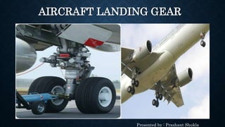
- 1. AIRCRAFT LANDING GEAR Presented by : Prashant Shukla
- 2. LEARNING OUTCOMES • Introduction • Location of the Landing Gears • Main Landing Gear • Multiple-axle Landing Gears • Nose Landing Gear • Purpose of Landing Gear • Shock Absorbers
- 3. INTRODUCTION • Undercarriage of an aircraft or Spacecraft. • Supports the entire weight of an aircraft during landing and ground operations. • Spacecraft L.G mainly design to support the vehicle in post-flight. • Mainly used for Landing, Take-off and Taxing. • Attached to primary structural member of the aircraft. • Comes in two configuration; Fixed and Retractable.
- 4. FIXED LANDING GEAR • A gear is attached to the airframe and remains exposed.
- 5. RETRACTABLE LANDING GEAR • Used in Faster aircraft and all new conventional aircraft. • Less fuel consumption. • Less drag and more speed.
- 6. VARIOUS SURFACES LANDING GEAR • Wheels are typically use for hard surface. • Skis for snow. • Floats for water. • Skids/Pontoons for helicopters.
- 7. LOCATION OF THE LANDING GEAR • Centre of gravity determines the location of the L.G. • C.G of an airplane with a tail gear is behind the main L.G. • C.G of an airplane with a nose gear is in front of the main L.G. • C.G must be in between the L.G for an even balance.
- 8. COMMON CONCEPT • There are two common concept with reference to L.G: 1. Track Maximum distance between the far right and far left main wheel. 2. Wheel Base Distance of the operating line through the wheel axle of the main L.G to the CenterPoint of nose wheel.
- 9. MAIN LANDING GEAR • Usually located behind the nose gear. • Retracted in a sideward direction. • Absorb large downward forces of the aeroplane. • Number of wheels in the Main L.G depends upon the overall mass of the aeroplane. • Initially, Main L.G had only one wheel. • Usually, aeroplanes have 4 to 6 wheels per main L.G and more than two wheels per aeroplane.
- 10. MULTIPLE-AXLE LANDING GEARS • Development of Multiple-axle landing gears caused due to the use of multiple wheels in the L.G. • In larger aircraft, multiple axles are attached to one common axle carrier known as bogie beam or gear trucks. • Gear trucks should always be in a certain position in relation to the strut during retraction in order to fit in the wheel wells. • Trim cylinder is use for bogie tilting.
- 11. NOSE LANDING GEAR • Nose gear have usually two wheels. • Mainly retracted in a forward direction. • Nose gear have same working principle as Main gear. • Nose wheel steering system are mainly actuated hydraulically but it can be operated either electrically or mechanically. • Nosewheel steering system provides directional control of the aircraft during ground operation. • Nose gear are mainly steerable when its shock absorber is compressed.
- 12. FUNCTION OF LANDING GEAR • Support the static load of the aircraft. • Used in taxing. • Absorb landing shock. • Provide manoeuvring on surface. • Dampen the vibration. • Facilitate take-off and landing.
- 13. SHOCK ABSORBER • One of the efficient shock absorber because of having long operating lives. • Also known as air/oil struts or oleo-strut. • Cushion the impact of landing and damp out the vertical oscillations. • Consists of inner metal tube known as piston and outer metal tube as cylinder. • Top cylinder is attached to the airframe and bottom to the L.G. • Bottom cylinder filled with hydraulic fluid and top cylinder with nitrogen gas.
- 14. SHOCK ABSORBER • It has three chambers which communicate through variable flow openings. • Chamber A and B are interconnected through the small gap exist between the metering pin and opening. • Chamber A and C are interconnected by a number of channels in the piston. • Metering pin is used to control the rate of fluid flow. • Compressed gas takes the entire load when aircraft is stationary.
- 15. DURING LANDING • Bottom cylinder forced into the top cylinder. • Pressure of the fluid increases as the volume decreases. • Fluid flows to top cylinder through the gap and as clearance is not enough, higher amount of heat develops in the fluid. • Heat is dissipated into the surrounding. • Chamber C volume increases. However, smaller than the volume B. • Fluid in Chamber C rises to Chamber A when it has streamed full. • Pressure of the nitrogen increases and small amount of landing energy transformed into a pressure increase. • This increase in pressure results shock absorption.