
Empfohlen
Weitere ähnliche Inhalte
Was ist angesagt?
Was ist angesagt? (20)
Ähnlich wie Field Transmitter Fundamentals: A Comprehensive Guide
Ähnlich wie Field Transmitter Fundamentals: A Comprehensive Guide (20)
Kürzlich hochgeladen
Kürzlich hochgeladen (20)
Field Transmitter Fundamentals: A Comprehensive Guide
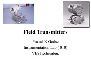
- 1. Field Transmitters Prasad K Godse Instrumentation Lab ( 010) VESIT,chembur.
- 2. Index • Introduction to Transmitters • Transmitter photographs • Transmitter classification • DP Transmitter - Detailed operation • Transmitter installation Guidelines and wiring diagram • Smart Transmitter Features • Transmitter specifications in details • Applications • Terminology • Selection criteria
- 3. Introduction to Transmitters • What is Transmitter? • Why Transmitters are used? • How Transmitters are used? • Transmitter Overview
- 4. What is Transmitter? • Transmitter is a secondary transducer • It converts physical signal directly OR signal generated by primary sensor • Responds to a measurement variable OR Measurand) into suitable signal level OR standardized Transmission signal which can be used for further processing OR can be displayed on indication system. • It is an instrument used to transmit the information in a standard format over a long distance. • Standard format signal levels for Electronic Transmitter is 4 – 20 mA DC @24 VDC; • Standard signal levels for Pneumatic Transmitter is 0.2 – 1 Kg / sq. CM (g) OR 3 – 15 psig ;
- 5. • Most Common Industrial Transmitter is a combination of Transducer & signal conditioning circuit that produces an output current proportional to measurand. • Process control industry’s standard current signal is 4 to 20 mA • 4 mA represents 0 % or Zero scale. • 20 mA represents 100 % or Full scale. • The Current signal is used because it is NOT affected by wire impedance & Noise.
- 6. Why Transmitter are used? • Signals generated by sensors / Transducers are very weak and unable to inform to indication / control system. • Output of a sensors affected by interferences. • Receiving systems/ instruments accepts standard signals only. • Sensors data is required to send over long distance.
- 7. How Transmitters are used? • Transmitters are signal conditioning systems which can be coupled with the sensors to convert sensor information into standard form of signals. • Standard signals are then transmitted through communication medium ( cables) over a long distance to the receiving devices/systems. • Thus Transmitters acts as converters.
- 8. TRANSMITTER OVERVIEW • Transmitters bring true precision to the measurement of flow, level, gage and absolute pressures, vacuum, and specific gravity. • With proven performance, quality, and reliability, they provides accurate measurement using the variable capacitance principle. • It is virtually unaffected by changes in temperature, static pressure, vibration, and power supply voltage.
- 9. Sensor Module S / C Module Sensor Module
- 11. • The Model 3051C Coplanar™ design is offered for Differential Pressure (DP),Gage Pressure (GP) and Absolute Pressure (AP) measurements. • The Model 3051C utilizes Rosemount Inc. capacitance sensor technology for DP and GP measurements. • Piezoresistive sensor technology is utilized in the Models 3051T and 3051C AP measurements. TRANSMITTER OVERVIEW
- 12. Transmitter Operation • The major components of the Model 3051 is the sensor module and the electronics housing. • The sensor module contains the oil filled sensor system (isolating diaphragms, oil fill system, and sensor) and the sensor electronics. • The sensor electronics are installed within the sensor module and include a temperature sensor (RTD), a memory module, and the capacitance to digital signal converter (C/D converter).
- 13. • The electrical signals from the sensor module are transmitted to the output electronics in the electronics housing. • The electronics housing contains the output electronics board (microprocessor, memory module, digital to analog signal converter or D/A converter), the local zero and span buttons, and the terminal block.
- 14. • When Differential pressure is applied to the isolating diaphragms, the oil deflects the center diaphragm, which then changes the capacitance. • This capacitance signal is then changed to a digital signal in the C/D converter. • The microprocessor then takes the signals from the RTD and C/D converter calculates the correct output of the transmitter. • This signal is then sent to the D/A converter, which converts the signal back to an analog signal and superimposes the HART signal on the 4-20 mA output.
- 27. Transmitter Classification • Based on the type of medium. – Electronic Output( Typical 4-20 mA DC) – Pneumatic Output ( 3-15 Psig) • Based on the signal Transmission. – Conventional ( Analog) – SMART or INTELLIGENT ( Analog + HART) – FF compatible( Digital) • Based on the Parameter measurement. • Transmitters are broadly classified based on the parameters to be measured . • Based on Mounting Arrangement.
- 28. Transmitter Classification based on Signal Transmission
- 29. Transmitter Classification based on parameter measurement
- 30. Transmitter Classification based on Type of Mounting Arrangement
- 31. Dimensional Drawing for DP Transmitter.
- 32. Differential Pressure (DP) Transmitter Exploded View.
- 34. DP Cell Sensor
- 36. DP Cell Sensor
- 42. Transmitter Installation Guidelines • General Considerations • Mechanical Considerations • Environmental Requirements • Access Requirements . • Process Flange Orientation • Housing Rotation • Terminal Side of Electronics Housing • Circuit Side of Electronics Housing • Exterior of Electronics Housing • Mounting Effects. • Process Connections
- 43. Typical DP Transmitter Installation
- 44. Installation • Mounting Requirements (for Steam, Liquid, Gas) . Taps • Drain/Vent Valves • Impulse Piping • Electrical Considerations • Wiring Conduit Sealing • Power Supply Grounding • Signal Wiring Transmitter Case • Grounding Effects
- 45. Pressure Transmitters- 2” pipe Mounting
- 46. GENERAL CONSIDERATIONS •The accuracy of a flow, pressure, or level measurement depends on proper installation of the transmitter and impulse piping. • The piping between the process and transmitter must accurately transmit process pressure to the transmitter. • Mount the transmitter close to the process and use a minimum of piping to achieve best accuracy. •Keep in mind, however, the need for easy access, safety of personnel, practical field calibration, and a suitable transmitter environment. • In general, install the transmitter so as to minimize vibration, shock, and temperature fluctuations. Installations in food, beverage, and pharmaceutical processes may require sanitary seals and fittings.
- 47. CONSIDERATIONS • Transmitters may be mounted in several ways. They may be panel-mounted, wall-mounted, or attached to a 2-inch pipe through an optional mounting bracket. • Mount the transmitter to minimize ambient temperature changes. The transmitter electronics temperature operating limits are either (–40 to 85 °C) or (–29 to 66 °C) or (–29 to 93 °C) • Mount the transmitter to avoid vibration and mechanical shock, and to avoid external contact with corrosive materials.
- 48. CONSIDERATIONS • When choosing an installation location and position, take into account the need for access to the transmitter. • Orient the process flanges to enable process connections to be made. • For safety reasons, orient the drain/vent valves so that process fluid is directed down and away from technicians when the valves are used. • consider the need for a testing or calibration input.
- 49. Electrical CONSIDERATIONS • Mount the transmitter so that the terminal side is accessible. • A ¾-inch clearance is required for cover removal with no meter. • A 3-inch clearance is required for cover removal if a meter is installed. • If practical, provide approximately 6 inches clearance so that a meter may be installed later. • The analog Model 1151 uses local span and zero screws, which are located under the nameplate on the side of the transmitter. • Allow 6 inches clearance if possible to allow access for on-site maintenance.
- 50. Mounting Requirements (for Steam, Liquid, Gas) Taps • Different measurement conditions call for different piping configurations.
- 51. For steam flow measurement •Place taps to the side of the line with the transmitter mounted below them, •To ensure that the impulse piping stays filled with condensate.
- 60. For liquid flow measurement •place taps to the side of the line to prevent sediment deposits, •and mount the transmitter beside or below these taps so gases can vent into the process line.
- 61. For gas flow measurement •place taps in the top or side of the line •mount the transmitter beside or above the taps so liquid will drain into the process line.
- 62. Drain/Vent Valves • For liquid service, mount the side drain/vent valve upward to allow the gases to vent. • For gas service, mount the drain/vent valve down to allow any accumulated liquid to drain. • For steam service, lines should be filled with water to prevent contact of the live steam with the transmitter.
- 63. LIQUID LEVEL MEASUREMENT • Differential pressure transmitters used for liquid level applications measure hydrostatic pressure head. • Liquid level and specific gravity of a liquid are factors in determining pressure head. This pressure is equal to the liquid height above the tap multiplied by the specific gravity of the liquid. • Pressure head is independent of volume or vessel shape.
- 64. Open Vessels • A pressure transmitter mounted near a tank bottom measures the pressure of the liquid above. • Connection are made to the high pressure side of the transmitter, and low pressure side is vent to the atmosphere. • Pressure head equals the liquid’s specific gravity multiplied by the liquid height above the tap. • Zero range suppression is required if the transmitter lies below the zero point of the desired level range. liquid level measurement example.
- 65. Closed Vessels • Pressure above a liquid affects the pressure measured at the bottom of a closed vessel. • The liquid specific gravity multiplied by the liquid height plus the vessel pressure equals the pressure at the bottom of the vessel. • To measure true level, the vessel pressure must be subtracted from the vessel bottom pressure. To do this, make a pressure tap at the top of the vessel and connect this to the low side of the transmitter. Vessel pressure is then equally applied to both the high and low sides of the transmitter. • The resulting differential pressure is proportional to liquid height multiplied by the liquid specific gravity.
- 66. Dry Leg Condition • it’s a condition when Low-side transmitter piping will remain empty if gas above the liquid does not condense. Wet Leg Condition •Condensation of the gas above the liquid slowly causes the low side of the transmitter piping to fill with liquid. •The pipe is purposely filled with a convenient reference fluid to eliminate this potential error. This is a wet leg condition.
- 67. Calibration • Calibration of the Rosemount Model 1151 Pressure Transmitter is simplified by its compact and explosion-proof design, external span and zero adjustments,
- 68. Transmitter Data Flow with Calibration Options.
- 69. This data flow can be summarized in four major steps: 1. Pressure is applied to the sensor. 2. A change in pressure is measured by a change in the sensor output. 3. The sensor signal is conditioned for various parameters. 4. The conditioned signal is converted to an appropriate analog output.
- 70. Zero and Span Adjustment Screws.
- 71. ZERO AND SPAN ADJUSTMENT • The zero and span adjustment screws are accessible externally behind the nameplate on the terminal side of the electronics housing. • The output of the transmitter increases with clockwise rotation of the adjustment screws. • The zero adjustment screw and ELEVATE ZERO/SUPPRESS ZERO jumper do not affect the span.
- 72. • Span adjustment, however, does affect zero. • This effect is minimized with zero-based spans. Therefore, when calibrations having elevated or suppressed zeros are made, it is easier to make a zero- based calibration and achieve the required elevation or suppression by adjusting the zero adjustment screw (and ELEVATE ZERO/SUPPRESS ZERO jumper as required). • For large amounts of elevation or suppression, it may be necessary to reposition the ELEVATE/SUPPRESS ZERO jumper. • To do this, remove the amplifier board, and move the jumper to the ELEVATE or SUPPRESS position as required.
- 74. Desired calibration of 0to 100 inH2O • 1. Adjust the zero. -With zero input applied to the transmitter, turn the zero adjustment screw until the transmitter reads 4 mA. • 2. Adjust the span. - Apply 100 inH2O to the transmitter high side connection. Turn the span adjustment screw until the transmitter output reads approximately 20 mA.
- 75. Desired calibration of 0to 100 inH2O • 3. Release the input pressure and readjust the zero output to read 4 mA ±0.032 mA. • 4. Re-apply 100 inH2O to the transmitter. If the output reading is greater than 20 mA, divide the difference by 3, and subtract the result from 20 mA. Adjust the 100% output to this value. • If the output reading is less than 20 mA, divide the difference by 3 and add the result to 20 mA. Adjust the 100% output to this value.
- 76. Damping and Linearity Adjustment Screws.
- 77. LINEARITY ADJUSTMENT • In addition to the span and zero adjustments, a linearity adjustment screw (marked LIN) is located on the solder side of the amplifier board. • This is a factory calibration adjusted for optimum performance over the calibrated range of the instrument and normally is not readjusted in the field. • The user may, however, maximize linearity over a particular range.
- 78. DAMPING ADJUSTMENT • The amplifier boards for output are designed to permit damping of rapid pulsations in the pressure source through adjustment of the damping screw shown in Figure • The adjustment is marked DAMP on the solder side of the amplifier board. The settings available provide time constant values between 0.2 and 1.66 seconds. • The instrument is calibrated and shipped with this control set at the counterclockwise stop (0.2 second time constant). • It is recommended that the shortest possible time constant setting be selected. Since the transmitter calibration is not influenced by the time constant setting, the damping may be adjusted with the transmitter connected to the process. • Turn the damping control clockwise until the desired damping is obtained.
- 79. STATIC PRESSURE SPAN CORRECTION FACTOR • High static pressure causes a systematic span shift in the transmitter. • It is linear and easily correctable during calibration.
- 80. Smart Transmitters • Smart Transmitters are microprocessor based, which can store data digitally to correct for sensor non- linearity’s & perform temp. OR pressure compensation.
- 83. Features of Smart Transmitters Contribution of microprocessor is to calibrate unit over a wide range than actual span needed for particular application. Zero / Span settings can be changed electronically through Keyboard. High Turndown ; i.e. Ability to adjust span setting (Sensing Range ) of a Transmitters. Allow for 2 way Communication with control Room. Standby sensor OR Multiple sensors facility allows to switch from an RTD to a TC sensor while using the same Transmitter. • It can also memorize and recall tag Numbers & Failure modes, provide Damping & Temperature Compensation.
- 84. Specifications • Functional Specifications • Performance Specifications. • Physical Specifications
- 86. Specifications FUNCTIONAL SPECIFICATIONS • Service- Liquid, gas, and vapor applications. • Ranges- Minimum span equals the upper range limit (URL) divided by rangedown. Rangedown varies with the output code. • Outputs • Analog - 4–20 mA dc, linear with process pressure. • Analog- 10–50 mA dc, linear with process pressure. • Analog- 4–20 mA dc, square root of differential input pressure between 4 and 100% of input. Linear with differential input pressure between 0 and 4% of input.
- 87. • Low Power- 0.8 to 3.2 V dc, linear with process pressure. • Low Power- 1 to 5 V dc, linear with process pressure. • Power Supply - External power supply required. Transmitter operates on: • 12 to 45 V dc with no load • 30 to 85 V dc with no load • 5 to 12 V dc for Output • 8 to 14 V dc for Output
- 88. • Current Consumption (Low Power Only) • Under Normal Operating Conditions • 1.5 mA dc.& 2.0 mA dc. • Span and Zero • Span and zero are continuously adjustable. • Hazardous Locations Certifications • Stainless steel certification tag is provided. • Temperature Limits-Electronics Operating • –40 to 200 °F (–40 to 93 °C). • –20 to 200 °F (–29 to 93 °C). • –20 to 150 °F (–29 to 66 °C). • Sensing element operating • Silicone fill: –40 to 220 °F (–40 to 104 °C). • Inert fill: 0 to 160 °F (–18 to 71 °C).
- 89. • Static Pressure Limits • Transmitters operate within specifications between the following limits: • Model 1151DP • 0.5 psia (3.45 kPa) to 2,000 psig (13790 kPa). • Model 1151HP • 0.5 psia (3.45 kPa) to 4,500 psig (31027 kPa). • Model 1151AP • 0 psia to the URL. • Model 1151GP • 0.5 psia (3.45 kPa) to the URL.
- 90. • Overpressure Limits • Transmitters withstand the following limits without damage: • Model 1151DP • 0 psia to 2,000 psig (0 to 13790 kPa). • Model 1151HP • 0 psia to 4,500 psig (0 to 31027 kPa). • Burst Pressure Limit • All models: 10,000 psig (68.95 MPa) burst pressure on the flanges. • Humidity Limits • 0 to 100% relative humidity. • Volumetric Displacement • Less than 0.01 in3 (0.16 cm3).
- 91. • Damping • Numbers given are for silicone fill fluid at room temperature. The minimum time constant is 0.2 seconds (0.4 seconds for Range 3). Inert filled sensor values would be slightly higher. • Turn-on Time • Maximum of 2.0 seconds with minimum damping. Low power output is within 0.2% of steady state value within 200 ms after application of power.
- 92. PERFORMANCE SPECIFICATIONS • Accuracy • ±0.2% of calibrated span for Model 1151DP & All other ranges and transmitters, ±0.25% of calibrated span. • Stability • ±0.2% of URL for six months & ±0.25 for all • other ranges. ±0.25% of URL for six months. • Short Circuit Condition No damage to the transmitter will result when the output is shorted to common or to power supply positive (limit 12 V). • Mounting Position Effect • Zero shift of up to 1 inH2O (0.24 kPa) that can be calibrated out.
- 93. • EMI/RFI Effect • Output shift of less than 0.1% of span when tested to IEC 801-3 from 20 to 1000 MHz and for field strengths up to 30 V/m.
- 94. PHYSICAL SPECIFICATIONS • (STANDARD CONFIGURATION) • Wetted Materials • Isolating Diaphragms • 316L SST, Hastelloy C-276, Monel, gold-plated Monel, or Tantalum. • Drain/Vent Valves • 316 SST, Hastelloy C, or Monel. • Process Flanges and Adaptors • Plated carbon steel, 316 SST, Hastelloy C, or Monel. • Wetted O-rings • Viton With gold-plated Monel diaphragms, • special fluorocarbon O-rings are supplied.
- 95. Non-wetted Materials • Fill Fluid • Silicone oil or inert fill. • Bolts and Bolting Flange (GP and AP only) • Plated carbon steel. • Electronics Housing • Low-copper aluminium. NEMA 4X. IP 65, IP 66. • Cover O-rings - Buna-N. • Paint - Polyurethane. • Process Connections - ¼–18 NPTF • Electrical Connections- ½–14 NPTF conduit entry • Weight - 12 lb (5.4 kg)
- 96. Applications • Petrochemical industry • Fertilizer industry • Pulp & paper industry • Sugar factory • Rubber chemicals • And many more.
- 106. • Calibration Operations that adjust for minor effects such as span shift and zero shift. These effects are usually caused by outside influences such as rotating a transmitter, or mounting a transmitter on its side. • Damping Output function that increases the response time of the transmitter to smooth the output when there are rapid input variations. • Lower Range Limit (LRL) Lowest value of the measured variable that the transmitter can be configured to measure. • Lower Range Value (LRV) Lowest value of the measured variable that the analog output of the transmitter is currently configured to measure. Terminology
- 107. • Reranging Configuration function that changes the transmitter 4 and 20 mA settings. • Span Algebraic difference between the upper and lower range values. • Upper Range Limit (URL) Highest value of the measured variable that the transmitter can be configured to measure. • Upper Range Value (URV) Highest value of the measured variable that the analog output of the transmitter is currently configured to measure. • Zero Trim A zero-based, one-point adjustment used in differential pressure applications to compensate for mounting position effects or zero shifts caused by static pressure.
- 108. Transmitter selection Guidelines • Nature of Process Variable • Type of Measurement / Transmission output • Performance characteristics • Applications • Budget
- 109. Any Questions ??? Thank You Contact : Prasad K Godse prasad.godse@ves.ac.in Process Instrumentation Lab 102/103