SlideShare ist ein Scribd-Unternehmen logo
1 von 16
Downloaden Sie, um offline zu lesen
Dept of IT | III YEAR | V SEMESTER IT E51 | COMPUTER HARDWARE AND TROUBLESHOOTING | UNIT 5
1 |Prepared By : Mr. PRABU.U/AP |Dept. of Computer Science and Engineering | SKCET |
UNIT V
Troubleshooting & Tools In-Circuit Emulators – Logic State/Timing Analyzers –
Digital Multimeters – CROs – Signature Analyzers – Troubleshooting problems of
system boards, add on cards and peripherals.
5.1 IN-CIRCUIT EMULATORS
 An in-circuit emulator (ICE) is a hardware device used to debug the software of an
embedded system.
 It was historically in the form of bond-out processor which has many internal signals
brought out for the purpose of debugging.
 These signals provide information about the state of the processor.
 The ICE is temporarily installed between the embedded system and an external
terminal or personal computer so that the programmer can observe and alter what
takes place in the embedded system, which has no display or keyboard of its own.
 An ICE serves as a "surrogate" CPU (central processing unit) for the microcomputer
in an embedded system.
 The ICE usually has a connector that fits the CPU socket in the system. If the
connector provided with the ICE does not match the socket in the system, a suitable
adapter can usually be found.
 An ICE can assist design engineers in product development, and also assist
programmers or end users in product upgrading, modification, or maintenance.
5.1.1 Using an Emulator or ICE
 A circuit for emulating target system remains independent of a particular targeted
system and processor.
 Emulator or ICE provides great flexibility and ease for developing various
applications on a single system in place of testing that multiple targeted systems.
Dept of IT | III YEAR | V SEMESTER IT E51 | COMPUTER HARDWARE AND TROUBLESHOOTING | UNIT 5
2 |Prepared By : Mr. PRABU.U/AP |Dept. of Computer Science and Engineering | SKCET |
5.1.2 Advantages
 Virtually all embedded systems have a hardware element and a software
element, which are separate but tightly interdependent.
 The ICE allows the software element to be run and tested on the actual hardware
on which it is to run, but still allows programmer conveniences to help isolate
faulty code, such as "source-level debugging" (which shows the program the way
the programmer wrote it) and single-stepping (which lets the programmer run
the program step-by-step to find errors).
 Most ICEs consist of an adaptor unit that sits between the ICE host computer and
the system to be tested. A header and cable assembly connects the adaptor to a
socket where the actual CPU or microcontroller mounts within the embedded
system.
5.1.3 Function
 The basic idea of an "in-circuit emulator" is that it provides a window into the
embedded system.
 The programmer uses the emulator to load programs into the embedded system,
run them, step through them slowly, and see and change the data used by the
system's software.
 An "emulator" gets its name because it often "emulates" the central processing
unit of the embedded system's computer.
 Often, it literally has a plug that plugs into the same socket as the CPU chip.
Emulating the main computer lets it do anything that the main computer can do,
but under the control of a programmer.
 ICEs are always tools that attach a terminal or PC to the embedded system. The
terminal or PC provides an interactive user interface for the programmer to
investigate and control the embedded system.
 Notably, when their program fails, most embedded systems simply become inert
lumps of nonfunctioning electronics.
 Embedded systems often lack basic functions to detect signs of software failure,
such as an MMU to catch memory access errors.
 Without an ICE, the development of embedded systems can be extremely
difficult, because there is usually no way to tell what went wrong.
 With an ICE, the programmer can usually test pieces of code, then isolate the
fault to a particular failing piece of code, and then inspect the failing code and
rewrite it to solve the problem.
 In usage, an ICE provides the programmer with execution breakpoints, memory
display & monitoring, and input/output control. Beyond this, the ICE can be
programmed to look for any range of matching criteria to pause at, hopefully
catching the failure's origin.
5.1.4 Features of Emulators, Simulators, and In-Circuit Debuggers
Parameters Software
Simulation
In-Circuit
Simulation
In-Circuit
Emulator
In-Circuit
Debugger
Real-time
execution
No No Yes Yes
Dept of IT | III YEAR | V SEMESTER IT E51 | COMPUTER HARDWARE AND TROUBLESHOOTING | UNIT 5
3 |Prepared By : Mr. PRABU.U/AP |Dept. of Computer Science and Engineering | SKCET |
Parameters Software
Simulation
In-Circuit
Simulation
In-Circuit
Emulator
In-Circuit
Debugger
Low cost Yes/Low/Free Yes/Low No/High Yes/Low
Full device
peripheral
implementation
No/Limited Yes/Limited Yes Yes
Automatic
download of
new program
Yes Yes Yes Yes
No loss of target
device I/O pins
when debugging
Yes/Sometimes Yes/Sometimes Yes No
Target system
cabling
None Complex Complex Simple
View and
modify RAM
and peripherals
Yes Yes/Limited Yes Yes
I/O resources
needed to
support
debugging
None Serial port,
some I/O pins
None Two or fewer
I/O
No loss of
program
memory or data
RAM
Yes No Yes No
Simple
connectivity of
debugger to
target
None No/Complex No/Complex Yes
Real-time trace
buffer
No/Limited No/Limited Yes No
Single stepping Yes Yes Yes Yes
Hardware
breakpoints
Yes/Unlimited One/Unlimited One/Unlimited Yes/One
5.2 LOGIC STATE/TIMING ANALYSERS
 A logic analyzer is an electronic instrument that captures and displays multiple
signals from a digital system or digital circuit.
 A logic analyzer may convert the captured data into timing diagrams, protocol
decodes, state machine traces, assembly language, or may correlate assembly
with source-level software. Logic Analyzers have advanced triggering
capabilities, and are useful when a user needs to see the timing relationships
between many signals in a digital system
 When logic analyzers first came into use, it was common to attach several
hundred "clips" to a digital system. Later, specialized connectors came into use.
Dept of IT | III YEAR | V SEMESTER IT E51 | COMPUTER HARDWARE AND TROUBLESHOOTING | UNIT 5
4 |Prepared By : Mr. PRABU.U/AP |Dept. of Computer Science and Engineering | SKCET |
 The evolution of logic analyzer probes has led to a common footprint that
multiple vendors support, which provides added freedom to end users.
When to use a logic analyzer ?
 When one wishes to observe many signals at the same time.
 When it's necessary to look at signals in the system the same way hardware
does.
 When it's required to trigger on a pattern of highs and lows on several lines and
see the results.
5.2.1 Logic analyser types
 Modular logic analyzers : This type of logic analyser is probably what may be
thought of as the most typical form of test instrument, although it is the highest
cost option providing the highest level of functionality. It comprises a chassis and
the various modules - including channel modules. The number of modules being
larger for the higher channel counts.
 Portable logic analyzers : In a number of instances there may be a need for a
smaller analyser, possibly for restricted budgets or for field service. These test
instruments incorporate all elements of the analyser into a single box for ease of
transportation.
 PC based logic analyzers: There is a growing number of PC based logic
analysers. These consist of an analyser unit that is connected to a PC. USB is an
obvious option for this, but Ethernet is also widely used because of its high
speed. This form of PC based instrument uses the processing power of the PC
combined with its display to reduce the cost of the overall system.
5.2.2 Uses
 Many digital designs, including those of ICs, are simulated to detect defects
before the unit is constructed.
 The simulation usually provides logic analysis displays. Often, complex discrete
logic is verified by simulating inputs and testing outputs using boundary scan.
 Logic analyzers can uncover hardware defects that are not found in simulation.
 These problems are typically too difficult to model in simulation, or too time
consuming to simulate and often cross multiple clock domains.
5.2.3 Operation
 A logic analyzer can trigger on a complicated sequence of digital events, and then
capture a large amount of digital data from the system under test (SUT).
 The best logic analyzers behave like software debuggers by showing the flow of
the computer program and decoding protocols to show messages and violations.
 When logic analyzers first came into use, it was common to attach several
hundred "clips" to a digital system. Later, specialized connectors came into use.
 The evolution of logic analyzer probe has led to a common footprint that
multiple vendors support, which provides added freedom to end users.
 Once the probes are connected, the user programs the analyzer with the names
of each signal, and can group several signals into groups for easier manipulation.
 Next, a capture mode is chosen, either timing mode, where the input signals are
sampled at regular intervals based on an internal or external clock source, or
state mode, where one or more of the signals are defined as "clocks," and data is
Dept of IT | III YEAR | V SEMESTER IT E51 | COMPUTER HARDWARE AND TROUBLESHOOTING | UNIT 5
5 |Prepared By : Mr. PRABU.U/AP |Dept. of Computer Science and Engineering | SKCET |
taken on the rising or falling edges of these clocks, optionally using other signals
to qualify these clocks.
 After the mode is chosen, a trigger condition must be set. A trigger condition can
range from simple (such as triggering on a rising or falling edge of a single
signal), to the very complex (such as configuring the analyzer to decode the
higher levels of the TCP/IP stack and triggering on a certain HTTP packet).
 At this point, the user sets the analyzer to "run" mode, either triggering once, or
repeatedly triggering.
 Once the data is captured, it can be displayed several ways, from the simple
(showing waveforms or state listings) to the complex (showing decoded
Ethernet protocol traffic).
 The analyzer can also operate in a "compare" mode, where it compares each
captured data set to a previously recorded data set, and stopping triggering
when this data set is either matched or not.
 This is useful for long-term empirical testing. Recent analyzers can even be set to
email a copy of the test data to the engineer on a successful trigger.
5.3 MULTIMETER
 A multimeter or a multitester is an electronic measuring instrument that
combines several functions in one unit. The most basic instruments include an
ammeter, voltmeter, and ohmmeter.
 Analog multimeters are sometimes referred to as "volt-ohm-meters",
abbreviated VOM.
 Digital multimeters are usually referred to as "digital-multi-meters", abbreviated
DMM.
 A multimeter can be a handheld device useful for basic fault finding and field
service work or a bench instrument which can measure to a very high degree of
accuracy.
 Such an instrument will commonly be found in a calibration lab and can be used
to characterized resistance and voltage standards or adjust and verify the
performance of multi-function calibrators.
5.3.1 A Digital Multimeter
 Current, voltage, and resistance measurements are considered standard features
for multimeters.
 AVO multimeters, a manufacturer of early multimeters, derived their name from
amperes, volts, and ohms, the units used for the measurement of current,
voltage, and resistance.
 Multimeters are available in a wide ranges of features and prices.
 They are extremely handy devices to have around the house as they can be used
to troubleshoot electrical problems in a wide array of household devices such as
possibly dead batteries, washing and drying machines, kitchen appliances, and
even automobile electronics and electrical systems.
Dept of IT | III YEAR | V SEMESTER IT E51 | COMPUTER HARDWARE AND TROUBLESHOOTING | UNIT 5
6 |Prepared By : Mr. PRABU.U/AP |Dept. of Computer Science and Engineering | SKCET |
5.3.2 An Analog Multimeter
Newer equipment can measure many other quantities. Some common additional
measured quantities and the units in which they are measured:
 Inductance in henrys.
 Capacitance in farads.
 Conductance in siemens.
 Temperature in degrees Celsius or Fahrenheit.
 Frequency in hertz.
 Duty cycle as a percentage.
A multimeter may be implemented with an analog meter deflected by an
electromagnet, as a classic galvanometer; or with a digital display such as an LCD or
Vacuum fluorescent display.
Analog multimeters are not hard to find in the used market, but are not very
accurate because of errors introduced in zeroing and reading the analog meter face.
Analog meters may be implemented with vacuum tubes to precondition and
amplify the input signal. Such meters are known as vacuum tube volt meters (VTVM) or
vacuum tube multimeters (VTMM).
5.3.3 Resolution
The resolution of a multimeter is often specified in "digits" of resolution. The
term "digits" dates back to the 1970's when multimeter vendors were very proud of
how many digits their products could display.
 A 5½ digit multimeter would have five full digits that display values from 0 to 9
and one half digit that could only display 0 or 1.
 This digital multimeter could show positive or negative values from 0 to
199,999.
 For a modern DMM, such as a PC-based multimeter, the term "digits" actual maps
to the noise performance of the device.
5.3.4 Common Features
 Modern multimeters are exclusively digital, and identified by the term DMM or
digital multimeter.
 In such an instrument, the signal under test is converted to a digital voltage and
an amplifier with an electronically controlled gain preconditions the signal.
 Similarly, better circuitry and electronics have improved meter accuracy. Older
analog meters might have basic accuracies of five to ten percent.
 Modern portable DMMs may have accuracies as good as ±0.025%, and bench-top
instruments have accuracies in the single-digit parts per million figures.
5.3.5 Commonly Available Measurement Enhancements
 Current-limited tests for voltage drop across semiconductor junctions. While not
a replacement for a transistor tester, this facilitates testing diodes and a variety
of transistor types.
 A graphic representation of the quantity under test, as a bar graph. This makes
go/no-go testing easy.
 A continuity tester that beeps when a circuit conducts.
 A low-bandwidth oscilloscope.
 A telephone test set.
Dept of IT | III YEAR | V SEMESTER IT E51 | COMPUTER HARDWARE AND TROUBLESHOOTING | UNIT 5
7 |Prepared By : Mr. PRABU.U/AP |Dept. of Computer Science and Engineering | SKCET |
 Automotive circuit testers, including tests for automotive timing and dwell
signals.
 Simple data acquisition features to record maximum and minimum readings
over a given period, or to take a number of samples at fixed intervals.
 Sample and hold, which will latch the most recent reading for examination after
the instrument is removed from the circuit under test.
5.3.6 Probes
 A multimeter can utilize a variety of test probes to connect to the circuit or
device under test.
 Crocodile clips, retractable hook clips, and pointed probes are the three most
common attachments.
 The connectors are attached to flexible, thickly-insulated leads that are
terminated with connectors appropriate for the meter.
 Handheld meters typically use shrouded or recessed banana jacks, while bench
top meters may use banana jacks or BNC connectors.
5.4 CATHODE-RAY OSCILLOSCOPE (CRO)
 The Cathode-Ray Oscilloscope (CRO) is a common laboratory instrument that
provides accurate time and amplitude measurements of voltage signals over a wide
range of frequencies. Its reliability, stability, and ease of operation make it suitable as
a general purpose laboratory instrument.
 The Cathode Ray Oscilloscope consists of Cathode-ray tube , timebase circuit ,
vertical amplifier, trigger circuit and power supply as shown in the block diagram of
CRO.
5.4.1 Block diagram of CRO:
Dept of IT | III YEAR | V SEMESTER IT E51 | COMPUTER HARDWARE AND TROUBLESHOOTING | UNIT 5
8 |Prepared By : Mr. PRABU.U/AP |Dept. of Computer Science and Engineering | SKCET |
5.4.2 Cathode-ray Tube:
Main part Component Function
Filament When a current passes through the filament, the
filament becomes hot and heats up the cathode.
Cathode Emits electrons when it is hot.
Control Grid  Control the number of electrons hitting the
fluorescent screen.
 Control the brightness of the spot on the screen.
Focusing Anode To focus the electrons onto the screen.
Accelerating
Anode
To accelerate the electrons to high speed.
Y-Plates To deflect the electron beam vertically.
X-Plates To deflect the electron beam horizontally.
Glass surface
coated with a
fluorescent
material.
To convert the kinetic energy of the electrons to heat
and light energy when the electrons hit the screen.
Electron gun
Deflecting
system
Fluorescent
screen
Dept of IT | III YEAR | V SEMESTER IT E51 | COMPUTER HARDWARE AND TROUBLESHOOTING | UNIT 5
9 |Prepared By : Mr. PRABU.U/AP |Dept. of Computer Science and Engineering | SKCET |
5.4.3 Description:
 The interior of the Cathode ray tube is a very good vacuum, with a pressure of
around 0.01 Pa (10−7 atm) or less.
 At pressure, collisions of electrons with air molecules would scatter the electron
beam excessively.
 The cathode, at the left end in the figure, is raised to a high temperature by the
heater, and electrons evaporate from the surface of the cathode.
5.4.4 CRO Operation:
 The cathode ray is a beam of electrons which are emitted by the heated cathode
(negative electrode) and accelerated toward the fluorescent screen.
 The assembly of the cathode, intensity grid, focus grid, and accelerating anode
(positive electrode) is called an electron gun. Its purpose is to generate the
electron beam and control its intensity and focus.
 Between the electron gun and the fluorescent screen are two pair of metal plates
- one oriented to provide horizontal deflection of the beam and one pair oriented
to give vertical deflection to the beam.
 These plates are thus referred to as the horizontal and vertical deflection plates.
 The combination of these two deflections allows the beam to reach any portion
of the fluorescent screen.
 Wherever the electron beam hits the screen, the phosphor is excited and light is
emitted from that point.
 This conversion of electron energy into light allows us to write with points or
lines of light on an otherwise darkened screen.
5.4.5 Features and Uses
1. Exterior
 A typical oscilloscope is usually box shaped with a display screen, numerous
input connectors, control knobs and buttons on the front panel.
 To aid measurement, a grid called the graticule is drawn on the face of the
screen. Each square in the graticule is known as a division.
2. Inputs
 The signal to be measured is fed to one of the input connectors, which is usually
a coaxial connector such as a BNC or N type
 If the signal source has its own coaxial connector, then a simple coaxial cable is
used; otherwise, a specialized cable called a 'scope probe', supplied with the
oscilloscope is used.
3. The trace
 In its simplest mode, the oscilloscope repeatedly draws a horizontal line called
the trace across the middle of the screen from left to right.
 One of the controls, the time base control, sets the speed at which the line is
drawn, and is calibrated in seconds per division.
 If the input voltage departs from zero, the trace is deflected either upwards or
downwards.
Dept of IT | III YEAR | V SEMESTER IT E51 | COMPUTER HARDWARE AND TROUBLESHOOTING | UNIT 5
10 |Prepared By : Mr. PRABU.U/AP |Dept. of Computer Science and Engineering | SKCET |
4. Trigger
 To provide a more stable trace, modern oscilloscopes have a function called the
trigger. When using triggering, the scope will pause each time the sweep reaches
the extreme right side of the screen.
 The scope then waits for a specified event before drawing the next trace.
 The trigger event is usually the input waveform reaching some user-specified
threshold voltage in the specified direction (going positive or going negative).
5.4.6 Types of Trigger
 External trigger, a pulse from an external source connected to a dedicated input
on the scope.
 Edge trigger, an edge-detector that generates a pulse when the input signal
crosses a specified threshold voltage in a specified direction.
 Video trigger, a circuit that extracts synchronising pulses from video formats
such as PAL and NTSC and triggers the timebase on every line, a specified line,
every field, or every frame. This circuit is typically found in a waveform monitor
device.
 Delayed trigger, which waits a specified time after an edge trigger before
starting the sweep. No trigger circuit acts instantaneously, so there is always a
certain delay, but a trigger delay circuit extends this delay to a known and
adjustable interval. In this way, the operator can examine a particular pulse in a
long train of pulses.
5.5 SIGNATURE ANALYSERS
Signature Analysis is an easy-to-use and highly accurate technique for identifying
faulty logic nodes.
 It is one specialized class of test instruments used in product development,
production, and field services.
 It can be very effective in troubleshooting microprocessor systems by
converting serial data, streams present on microprocessor system logic
nodes into four-digit “signatures” and these signatures tell whether or not
the nodes is performing properly.
5.5.1 Function of Signature analyzer
 Signature analyzer is a pattern detector.
 Signature analyzer can detect what activities occur more than once, and calls
them patterns.
 These patterns can be detected from text input, MIDI code input and analogue
x,y,z input.
 Signature database puts every pattern found in a database containing:
 A pointer to the particular sensor(s).
 Time stamps of the starting points of these activities.
 Number of reoccurrences of a pattern ("frequency").
 Length of each pattern.
 Impact of any pattern (= freq times length of a pattern). Analysis afterwards
can compute the impact of a pattern as a percentage of the whole session.
 Anything more if necessary.
Dept of IT | III YEAR | V SEMESTER IT E51 | COMPUTER HARDWARE AND TROUBLESHOOTING | UNIT 5
11 |Prepared By : Mr. PRABU.U/AP |Dept. of Computer Science and Engineering | SKCET |
5.5.2 HP 5004A model
Signature analyser interprets incoming data as background noise and detects
reoccurrences as an argument to find any identifiable object. The reoccurrence itself
identifies the object by pointing at the other occurrence.
 Signature analyser transforms noise to objects in an unsupervised manner.
 Signature analyser detects patterns in different hierarchical levels.
 Signature database can be used to give names to patterns like: walking, standing
up, jumping etc. (supervised learning).
5.6 TROUBLESHOOTING PROBLEMS OF SYSTEM BOARDS, ADD ON CARDS AND
PERIPHERALS.
More than 70% of all computer problems are related to cabling and connections.
Ensure all cables are connected and connected firmly. IDE and floppy ribbon cables and
power cables can often go loose. Ensure microprocessor, memory modules, and
adapters such as video card are inserted correctly and didn't "pop-up" due to vibration.
How to troubleshoot a Windows PC Motherboard?
Operating System will not load? Reseat RAM - if multiple SIMMS (single inline
memory modules) or DIMMS (dual inline memory modules) then remove them all and
replace and test individually. Did you install after market RAM? Is it compatible? Is it
sequenced correctly - must be in pairs? Is it the correct amount of RAM?
 POST Codes (Power On Self Test) - Computer Beeps at start up - Reseat the PCI
cards. For notebooks then reseat the mini-PCI bus. Reseat the RAM.
 For Notebooks - perform a hard reset.
 Perform Diagnostics test.
 Perform an MSCONFIG if your computer has it.
 Shut down all other applications to avoid conflicts. Remove all other hardware
devices.
 Perform a recovery. Ensure that you backup your data prior to doing a recovery.
 If the problem persists then send in for service.
 Check error messages in Event Viewer. Start / Settings / Control Panel /
Administrative Tools / Computer Management (or Event Viewer)
 CPU Heat - check to ensure that there is proper ventilation and the fan is
working. For notebook heat issues - use SPEEDSTEP (Intel) to the lower the
cycle speed (megahertz). Enable Battery Optimized Performance. Was your CPU
replaced? Was the thermal barrier replaced correctly. The CPU must be sealed
correctly with a thermal barrier (adhesive between CPU and motherboard) or it
could cause heat problems.
 Conflicts in system devices - check the IRQ (Interrupt Requests 0-15) in the BIOS
and reset the BIOS.
System has no power at all. Power light does not illuminate, fan inside the power
supply does not turn on, and indicator light on keyboard does not turn on.
PROBABLE CAUSE DIAGNOSIS SOLUTION
Power cable is unplugged.
Visually inspect power
cable.
Make sure power cable is
securely plugged in.
Defective power cable.
Visual inspection, try
another cable.
Replace cable.
Dept of IT | III YEAR | V SEMESTER IT E51 | COMPUTER HARDWARE AND TROUBLESHOOTING | UNIT 5
12 |Prepared By : Mr. PRABU.U/AP |Dept. of Computer Science and Engineering | SKCET |
Power supply failure.
Power cable and wall socket
are OK, but system is still
dead.
Contact technical support
Faulty wall outlet; circuit
breaker or fuse blown.
Plug device into socket
know to work and test.
Use different socket, repair
outlet, reset circuit breaker
or replace fuse.
System inoperative. Keyboard lights are on, power indicator lights are lit, and
hard drive is spinning.
PROBABLE CAUSE DIAGNOSIS SOLUTION
Expansion card is partially
dislodged from expansion
slot on the motherboard.
Turn off computer. Take
cover off system unit.
Check all expansion cards to
ensure they are securely
seated in slots.
Using even pressure on both
ends of the expansion card,
press down firmly on
expansion card.
Defective floppy disk drive
or tape drive.
Turn system off.
Disconnect the cables from
one of the floppy drives.
Turn on the system, check
to see if the keyboard
operates normally. Repeat
until you have located
defective unit.
Contact Technical Support.
Defective expansion card.
Turn computer off.
Remove an expansion card.
Make sure expansion card is
secure in expansion socket.
System does not boot from hard disk drive, can be booted from floppy disk drive.
PROBABLE CAUSE DIAGNOSIS SOLUTION
Connector between hard
drive and system board
unplugged.
When attempting to run the
FDISK utility described in
the HARD DISK section of
the manual you get a
message, INVALID DRIVE
SPECIFICATION.
Check cable running form
disk to disk controller on the
board. Make sure both ends
are securely plugged in;
check the drive type in the
Standard CMOS Setup (in
your motherboard manual).
Damaged Hard Disk or Disk
Controller.
Format hard disk; if unable
to do so, the hard disk may
be defective.
Contact Technical Support.
Hard Disk directory or FAT
is scrambled.
Run the FDISK program,
format the hard drive(See
HARD DRIVE section of
manual). Copy your backup
data back onto hard drive.
Backing up the hard drive is
extremely important. All
Hard Disks are capable of
breaking down at any time.
Dept of IT | III YEAR | V SEMESTER IT E51 | COMPUTER HARDWARE AND TROUBLESHOOTING | UNIT 5
13 |Prepared By : Mr. PRABU.U/AP |Dept. of Computer Science and Engineering | SKCET |
System only boots from Floppy Disk. Hard Disk can be read and applications can
be used, but booting from Hard Disk is impossible.
PROBABLE CAUSE DIAGNOSIS SOLUTION
Hard Disk boot program has
been destroyed.
A number of causes could
be behind this.
Back up data and
applications files.
Reformat the Hard Drive as
described in the Hard Drive
section of the manual. Re-
install applications and data
using backup disks.
Error message reading "SECTOR NOT FOUND" or other error messages indication
certain data is not allowed to be retrieved.
PROBABLE CAUSE DIAGNOSIS SOLUTION
A number of causes could
be behind this.
Use a file by file backup
instead of an image backup
to backup the Hard Disk.
Back up any salvageable
data. Then do a low level
format, partition, and high
level format of the hard
drive( see Hard Disk section
of your manual for
instructions). Re-install all
saved data when completed.
Disk formatted on IBM PS/2 will not operate with this system.
PROBABLE CAUSE DIAGNOSIS SOLUTION
The IBM PS/2 uses a
different format than other
computers.
IBM PS/2 disk format will
not work in an AT type
computer.
Format disk in the AT type
computer insert disk into the
IBM PS/2 and copy the files
you wish.
After install an expansion card (network card, tape drive card, etc.) the system no
longer works properly.
PROBABLE CAUSE DIAGNOSIS SOLUTION
No power to monitor.
All or part of the system
may be inoperable. The new
card may work but a mouse
or COM port may not work.
Change the interrupt or RAM
address on the new
expansion card. See the
documentation that came
with the new card in order to
change pin settings. many
expansion devices come with
proprietary software that
will assist you in doing this.
Dept of IT | III YEAR | V SEMESTER IT E51 | COMPUTER HARDWARE AND TROUBLESHOOTING | UNIT 5
14 |Prepared By : Mr. PRABU.U/AP |Dept. of Computer Science and Engineering | SKCET |
Screen message says "Invalid Configuration" or "CMOS Failure."
PROBABLE CAUSE DIAGNOSIS SOLUTION
Incorrect information
entered into the
configuration (setup)
program.
Check the configuration
program. Replace any
incorrect information.
Review system's equipment.
Make sure correct
information is in setup.
Screen is blank.
PROBABLE CAUSE DIAGNOSIS SOLUTION
No power to monitor.
Power connectors may be
loose or not plugged in.
Check the power connectors
to monitor and to system.
Make sure monitor is
connected to display card,
change I/O address on
network card if applicable.
Monitor not connected to
computer.
See instructions above.
Network card I/O address
conflict.
See instructions above.
System does not boot from hard disk drive, can be booted from floppy disk drive.
PROBABLE CAUSE DIAGNOSIS SOLUTION
Connector between hard
drive and system board
unplugged.
When attempting to run the
FDISK utility described in
the HARD DISK section of
the manual you get a
message, INVALID DRIVE
SPECIFICATION.
Check cable running form
disk to disk controller on the
board. Make sure both ends
are securely plugged in;
check the drive type in the
Standard CMOS Setup (in
your
Problem
PROBABLE CAUSE DIAGNOSIS SOLUTION
Memory problem, display
card jumpers not set
correctly.
Reboot computer. Re-install
memory, make sure that all
memory modules are
installed in correct sockets.
Check jumper and switch
settings on display card. See
display card section for
information of settings.
Computer virus.
Use anti-virus programs
(McAfee/PC-cillin, E-port,
etc) to detect and clean
viruses.
Dept of IT | III YEAR | V SEMESTER IT E51 | COMPUTER HARDWARE AND TROUBLESHOOTING | UNIT 5
15 |Prepared By : Mr. PRABU.U/AP |Dept. of Computer Science and Engineering | SKCET |
Screen goes blank periodically.
PROBABLE CAUSE DIAGNOSIS SOLUTION
Screen saver is enabled. Disable screen saver.
Keyboard failure.
PROBABLE CAUSE DIAGNOSIS SOLUTION
Keyboard is disconnected.
Reconnect keyboard. Check
keys again, if no
improvement, replace
keyboard.
No color on screen.
PROBABLE CAUSE DIAGNOSIS SOLUTION
Faulty Monitor.
If possible, connect monitor
to another system. If no
color, replace monitor.
CMOS incorrectly set up. Call technical support.
Floppy drive lights stays on.
PROBABLE CAUSE DIAGNOSIS SOLUTION
Floppy Drive cable not
connected correctly.
Reconnect floppy cable
making sure PIN1 on the
Floppy Drive corresponds
with PIN1 on floppy cable
connector.
Error reading drive A:
PROBABLE CAUSE DIAGNOSIS SOLUTION
Bad floppy disk. Try new floppy disk.
Floppy disk not formatted
Format floppy disk(type
ENTER)
C: drive failure.
PROBABLE CAUSE DIAGNOSIS SOLUTION
SETUP program does not
have correct information.
Boot from drive A: using DOS
system disk. Input correct
information to SETUP
program.
Hard Drive cable not
connected properly.
Check Hard drive cable.
Dept of IT | III YEAR | V SEMESTER IT E51 | COMPUTER HARDWARE AND TROUBLESHOOTING | UNIT 5
16 |Prepared By : Mr. PRABU.U/AP |Dept. of Computer Science and Engineering | SKCET |
Cannot boot system after installing second hard drive.
PROBABLE CAUSE DIAGNOSIS SOLUTION
Master/Slave jumpers not
set correctly.
Set master /Slave jumpers
correctly.
Hard Drives not compatible
/ different manufacturers.
Run SETUP program and
select correct drive types.
Call drive manufactures for
compatibility with other
drives.
Missing operating system on hard drive.
PROBABLE CAUSE DIAGNOSIS SOLUTION
CMOS setup has been
changed.
Run setup and select correct
drive type.
Certain keys do not function.
PROBABLE CAUSE DIAGNOSIS SOLUTION
Keys jammed or defective. Replace keyboard.
Keyboard is locked, no keys function.
PROBABLE CAUSE DIAGNOSIS SOLUTION
Keyboard is locked. Unlock keyboard

Weitere ähnliche Inhalte

Was ist angesagt?

Design of embedded systems
Design of embedded systemsDesign of embedded systems
Design of embedded systems
Pradeep Kumar TS
 
Embedded system notes
Embedded system notesEmbedded system notes
Embedded system notes
TARUN KUMAR
 

Was ist angesagt? (20)

Introduction to Embedded Architecture
Introduction to Embedded Architecture Introduction to Embedded Architecture
Introduction to Embedded Architecture
 
Bios and cmos
Bios and cmosBios and cmos
Bios and cmos
 
E.s unit 6
E.s unit 6E.s unit 6
E.s unit 6
 
Computer architecture
Computer architecture Computer architecture
Computer architecture
 
Embedded system design process
Embedded system design processEmbedded system design process
Embedded system design process
 
Introduction to digital logic
Introduction to digital logicIntroduction to digital logic
Introduction to digital logic
 
Combinational circuits
Combinational circuitsCombinational circuits
Combinational circuits
 
Design of embedded systems
Design of embedded systemsDesign of embedded systems
Design of embedded systems
 
Embedded system
Embedded systemEmbedded system
Embedded system
 
Operating Systems - "Chapter 5 Process Synchronization"
Operating Systems - "Chapter 5 Process Synchronization"Operating Systems - "Chapter 5 Process Synchronization"
Operating Systems - "Chapter 5 Process Synchronization"
 
Encoder & Decoder
Encoder & DecoderEncoder & Decoder
Encoder & Decoder
 
Computer Organization Lecture Notes
Computer Organization Lecture NotesComputer Organization Lecture Notes
Computer Organization Lecture Notes
 
Bios ( Basic Input Output System )
Bios ( Basic Input Output System )Bios ( Basic Input Output System )
Bios ( Basic Input Output System )
 
Combinational circuits
Combinational circuits Combinational circuits
Combinational circuits
 
Embedded system notes
Embedded system notesEmbedded system notes
Embedded system notes
 
Computer architecture
Computer architectureComputer architecture
Computer architecture
 
Bios
BiosBios
Bios
 
Digital electronics
Digital electronicsDigital electronics
Digital electronics
 
Pipeline processing - Computer Architecture
Pipeline processing - Computer Architecture Pipeline processing - Computer Architecture
Pipeline processing - Computer Architecture
 
Motherboard, It's Functions and It's Components
Motherboard, It's Functions and It's ComponentsMotherboard, It's Functions and It's Components
Motherboard, It's Functions and It's Components
 

Ähnlich wie Troubleshooting & Tools

BEE 049- design of embedded system.pdf
BEE 049- design of embedded system.pdfBEE 049- design of embedded system.pdf
BEE 049- design of embedded system.pdf
abdisahirko
 
Embeddedsystem 110412132957-phpapp02
Embeddedsystem 110412132957-phpapp02Embeddedsystem 110412132957-phpapp02
Embeddedsystem 110412132957-phpapp02
ishan111
 

Ähnlich wie Troubleshooting & Tools (20)

Embedded Systems
Embedded SystemsEmbedded Systems
Embedded Systems
 
Software and Hardware Tools for Microprocessors
Software and Hardware Tools for MicroprocessorsSoftware and Hardware Tools for Microprocessors
Software and Hardware Tools for Microprocessors
 
BEE 049- design of embedded system.pdf
BEE 049- design of embedded system.pdfBEE 049- design of embedded system.pdf
BEE 049- design of embedded system.pdf
 
Introduction to EMBEDDED SYSTEM.pdf
Introduction to EMBEDDED SYSTEM.pdfIntroduction to EMBEDDED SYSTEM.pdf
Introduction to EMBEDDED SYSTEM.pdf
 
Embeddedsystem
EmbeddedsystemEmbeddedsystem
Embeddedsystem
 
4213ijsea06
4213ijsea064213ijsea06
4213ijsea06
 
SIMULATION-BASED APPLICATION SOFTWARE DEVELOPMENT IN TIME-TRIGGERED COMMUNICA...
SIMULATION-BASED APPLICATION SOFTWARE DEVELOPMENT IN TIME-TRIGGERED COMMUNICA...SIMULATION-BASED APPLICATION SOFTWARE DEVELOPMENT IN TIME-TRIGGERED COMMUNICA...
SIMULATION-BASED APPLICATION SOFTWARE DEVELOPMENT IN TIME-TRIGGERED COMMUNICA...
 
Low cost embedded system
Low cost embedded systemLow cost embedded system
Low cost embedded system
 
PLC, DCS and PLC vs DCS Presentation by Jitender Singh Shekhawat
PLC, DCS and PLC vs DCS Presentation by Jitender Singh ShekhawatPLC, DCS and PLC vs DCS Presentation by Jitender Singh Shekhawat
PLC, DCS and PLC vs DCS Presentation by Jitender Singh Shekhawat
 
Ppt on embedded system
Ppt on embedded systemPpt on embedded system
Ppt on embedded system
 
System Software ( Os )
System Software ( Os )System Software ( Os )
System Software ( Os )
 
Simulation of Signals with Field Signal Simulator
Simulation of Signals with Field Signal SimulatorSimulation of Signals with Field Signal Simulator
Simulation of Signals with Field Signal Simulator
 
EC8791 designing with computing platform
EC8791 designing with computing platformEC8791 designing with computing platform
EC8791 designing with computing platform
 
Introduction to embedded systems
Introduction to embedded systemsIntroduction to embedded systems
Introduction to embedded systems
 
Trainingreport on embedded system
Trainingreport on embedded systemTrainingreport on embedded system
Trainingreport on embedded system
 
Language for embedded system
Language for embedded systemLanguage for embedded system
Language for embedded system
 
Language for Embedded System
Language for Embedded System Language for Embedded System
Language for Embedded System
 
Julia - THE FIRST BRAIN COMPUTER FIELDBUS INTERFACE ON THE MARKET
Julia - THE FIRST BRAIN COMPUTER FIELDBUS INTERFACE ON THE MARKETJulia - THE FIRST BRAIN COMPUTER FIELDBUS INTERFACE ON THE MARKET
Julia - THE FIRST BRAIN COMPUTER FIELDBUS INTERFACE ON THE MARKET
 
Embeddedsystem 110412132957-phpapp02
Embeddedsystem 110412132957-phpapp02Embeddedsystem 110412132957-phpapp02
Embeddedsystem 110412132957-phpapp02
 
Embedded system
Embedded systemEmbedded system
Embedded system
 

Mehr von Prabu U

Mehr von Prabu U (20)

Computation Using Scipy, Scikit Image, Scikit Learn
Computation Using Scipy, Scikit Image, Scikit LearnComputation Using Scipy, Scikit Image, Scikit Learn
Computation Using Scipy, Scikit Image, Scikit Learn
 
Concurrency and Parallelism, Asynchronous Programming, Network Programming
Concurrency and Parallelism, Asynchronous Programming, Network ProgrammingConcurrency and Parallelism, Asynchronous Programming, Network Programming
Concurrency and Parallelism, Asynchronous Programming, Network Programming
 
File Input/output, Database Access, Data Analysis with Pandas
File Input/output, Database Access, Data Analysis with PandasFile Input/output, Database Access, Data Analysis with Pandas
File Input/output, Database Access, Data Analysis with Pandas
 
Arrays with Numpy, Computer Graphics
Arrays with Numpy, Computer GraphicsArrays with Numpy, Computer Graphics
Arrays with Numpy, Computer Graphics
 
Lambdas, Collections Framework, Stream API
Lambdas, Collections Framework, Stream APILambdas, Collections Framework, Stream API
Lambdas, Collections Framework, Stream API
 
Exception handling, Stream Classes, Multithread Programming
Exception handling, Stream Classes, Multithread ProgrammingException handling, Stream Classes, Multithread Programming
Exception handling, Stream Classes, Multithread Programming
 
String Handling, Inheritance, Packages and Interfaces
String Handling, Inheritance, Packages and InterfacesString Handling, Inheritance, Packages and Interfaces
String Handling, Inheritance, Packages and Interfaces
 
Classes and Objects
Classes and ObjectsClasses and Objects
Classes and Objects
 
Building XML Based Applications
Building XML Based ApplicationsBuilding XML Based Applications
Building XML Based Applications
 
Introduction to XML
Introduction to XMLIntroduction to XML
Introduction to XML
 
WEB SERVICES
WEB SERVICESWEB SERVICES
WEB SERVICES
 
XML
XMLXML
XML
 
SERVER SIDE PROGRAMMING
SERVER SIDE PROGRAMMINGSERVER SIDE PROGRAMMING
SERVER SIDE PROGRAMMING
 
Internet Principles and Components, Client-Side Programming
Internet Principles and Components, Client-Side ProgrammingInternet Principles and Components, Client-Side Programming
Internet Principles and Components, Client-Side Programming
 
Operation Management
Operation ManagementOperation Management
Operation Management
 
Nature and Importance of Management
Nature and Importance of ManagementNature and Importance of Management
Nature and Importance of Management
 
Replacement and Maintenance Analysis
Replacement and Maintenance AnalysisReplacement and Maintenance Analysis
Replacement and Maintenance Analysis
 
Elementary Economic Analysis
Elementary Economic AnalysisElementary Economic Analysis
Elementary Economic Analysis
 
Introduction to Engineering Economics
Introduction to Engineering EconomicsIntroduction to Engineering Economics
Introduction to Engineering Economics
 
Files in C
Files in CFiles in C
Files in C
 

Kürzlich hochgeladen

FULL ENJOY Call Girls In Mahipalpur Delhi Contact Us 8377877756
FULL ENJOY Call Girls In Mahipalpur Delhi Contact Us 8377877756FULL ENJOY Call Girls In Mahipalpur Delhi Contact Us 8377877756
FULL ENJOY Call Girls In Mahipalpur Delhi Contact Us 8377877756
dollysharma2066
 
Integrated Test Rig For HTFE-25 - Neometrix
Integrated Test Rig For HTFE-25 - NeometrixIntegrated Test Rig For HTFE-25 - Neometrix
Integrated Test Rig For HTFE-25 - Neometrix
Neometrix_Engineering_Pvt_Ltd
 
VIP Call Girls Ankleshwar 7001035870 Whatsapp Number, 24/07 Booking
VIP Call Girls Ankleshwar 7001035870 Whatsapp Number, 24/07 BookingVIP Call Girls Ankleshwar 7001035870 Whatsapp Number, 24/07 Booking
VIP Call Girls Ankleshwar 7001035870 Whatsapp Number, 24/07 Booking
dharasingh5698
 
Call Girls in Netaji Nagar, Delhi 💯 Call Us 🔝9953056974 🔝 Escort Service
Call Girls in Netaji Nagar, Delhi 💯 Call Us 🔝9953056974 🔝 Escort ServiceCall Girls in Netaji Nagar, Delhi 💯 Call Us 🔝9953056974 🔝 Escort Service
Call Girls in Netaji Nagar, Delhi 💯 Call Us 🔝9953056974 🔝 Escort Service
9953056974 Low Rate Call Girls In Saket, Delhi NCR
 
Top Rated Call Girls In chittoor 📱 {7001035870} VIP Escorts chittoor
Top Rated Call Girls In chittoor 📱 {7001035870} VIP Escorts chittoorTop Rated Call Girls In chittoor 📱 {7001035870} VIP Escorts chittoor
Top Rated Call Girls In chittoor 📱 {7001035870} VIP Escorts chittoor
dharasingh5698
 
Standard vs Custom Battery Packs - Decoding the Power Play
Standard vs Custom Battery Packs - Decoding the Power PlayStandard vs Custom Battery Packs - Decoding the Power Play
Standard vs Custom Battery Packs - Decoding the Power Play
Epec Engineered Technologies
 
Call Now ≽ 9953056974 ≼🔝 Call Girls In New Ashok Nagar ≼🔝 Delhi door step de...
Call Now ≽ 9953056974 ≼🔝 Call Girls In New Ashok Nagar  ≼🔝 Delhi door step de...Call Now ≽ 9953056974 ≼🔝 Call Girls In New Ashok Nagar  ≼🔝 Delhi door step de...
Call Now ≽ 9953056974 ≼🔝 Call Girls In New Ashok Nagar ≼🔝 Delhi door step de...
9953056974 Low Rate Call Girls In Saket, Delhi NCR
 

Kürzlich hochgeladen (20)

FULL ENJOY Call Girls In Mahipalpur Delhi Contact Us 8377877756
FULL ENJOY Call Girls In Mahipalpur Delhi Contact Us 8377877756FULL ENJOY Call Girls In Mahipalpur Delhi Contact Us 8377877756
FULL ENJOY Call Girls In Mahipalpur Delhi Contact Us 8377877756
 
Integrated Test Rig For HTFE-25 - Neometrix
Integrated Test Rig For HTFE-25 - NeometrixIntegrated Test Rig For HTFE-25 - Neometrix
Integrated Test Rig For HTFE-25 - Neometrix
 
VIP Call Girls Ankleshwar 7001035870 Whatsapp Number, 24/07 Booking
VIP Call Girls Ankleshwar 7001035870 Whatsapp Number, 24/07 BookingVIP Call Girls Ankleshwar 7001035870 Whatsapp Number, 24/07 Booking
VIP Call Girls Ankleshwar 7001035870 Whatsapp Number, 24/07 Booking
 
Call Girls in Netaji Nagar, Delhi 💯 Call Us 🔝9953056974 🔝 Escort Service
Call Girls in Netaji Nagar, Delhi 💯 Call Us 🔝9953056974 🔝 Escort ServiceCall Girls in Netaji Nagar, Delhi 💯 Call Us 🔝9953056974 🔝 Escort Service
Call Girls in Netaji Nagar, Delhi 💯 Call Us 🔝9953056974 🔝 Escort Service
 
Hostel management system project report..pdf
Hostel management system project report..pdfHostel management system project report..pdf
Hostel management system project report..pdf
 
(INDIRA) Call Girl Meerut Call Now 8617697112 Meerut Escorts 24x7
(INDIRA) Call Girl Meerut Call Now 8617697112 Meerut Escorts 24x7(INDIRA) Call Girl Meerut Call Now 8617697112 Meerut Escorts 24x7
(INDIRA) Call Girl Meerut Call Now 8617697112 Meerut Escorts 24x7
 
Block diagram reduction techniques in control systems.ppt
Block diagram reduction techniques in control systems.pptBlock diagram reduction techniques in control systems.ppt
Block diagram reduction techniques in control systems.ppt
 
data_management_and _data_science_cheat_sheet.pdf
data_management_and _data_science_cheat_sheet.pdfdata_management_and _data_science_cheat_sheet.pdf
data_management_and _data_science_cheat_sheet.pdf
 
Introduction to Serverless with AWS Lambda
Introduction to Serverless with AWS LambdaIntroduction to Serverless with AWS Lambda
Introduction to Serverless with AWS Lambda
 
Minimum and Maximum Modes of microprocessor 8086
Minimum and Maximum Modes of microprocessor 8086Minimum and Maximum Modes of microprocessor 8086
Minimum and Maximum Modes of microprocessor 8086
 
Call Girls Wakad Call Me 7737669865 Budget Friendly No Advance Booking
Call Girls Wakad Call Me 7737669865 Budget Friendly No Advance BookingCall Girls Wakad Call Me 7737669865 Budget Friendly No Advance Booking
Call Girls Wakad Call Me 7737669865 Budget Friendly No Advance Booking
 
Top Rated Call Girls In chittoor 📱 {7001035870} VIP Escorts chittoor
Top Rated Call Girls In chittoor 📱 {7001035870} VIP Escorts chittoorTop Rated Call Girls In chittoor 📱 {7001035870} VIP Escorts chittoor
Top Rated Call Girls In chittoor 📱 {7001035870} VIP Escorts chittoor
 
University management System project report..pdf
University management System project report..pdfUniversity management System project report..pdf
University management System project report..pdf
 
Unleashing the Power of the SORA AI lastest leap
Unleashing the Power of the SORA AI lastest leapUnleashing the Power of the SORA AI lastest leap
Unleashing the Power of the SORA AI lastest leap
 
UNIT - IV - Air Compressors and its Performance
UNIT - IV - Air Compressors and its PerformanceUNIT - IV - Air Compressors and its Performance
UNIT - IV - Air Compressors and its Performance
 
Hazard Identification (HAZID) vs. Hazard and Operability (HAZOP): A Comparati...
Hazard Identification (HAZID) vs. Hazard and Operability (HAZOP): A Comparati...Hazard Identification (HAZID) vs. Hazard and Operability (HAZOP): A Comparati...
Hazard Identification (HAZID) vs. Hazard and Operability (HAZOP): A Comparati...
 
Double Revolving field theory-how the rotor develops torque
Double Revolving field theory-how the rotor develops torqueDouble Revolving field theory-how the rotor develops torque
Double Revolving field theory-how the rotor develops torque
 
Standard vs Custom Battery Packs - Decoding the Power Play
Standard vs Custom Battery Packs - Decoding the Power PlayStandard vs Custom Battery Packs - Decoding the Power Play
Standard vs Custom Battery Packs - Decoding the Power Play
 
Thermal Engineering-R & A / C - unit - V
Thermal Engineering-R & A / C - unit - VThermal Engineering-R & A / C - unit - V
Thermal Engineering-R & A / C - unit - V
 
Call Now ≽ 9953056974 ≼🔝 Call Girls In New Ashok Nagar ≼🔝 Delhi door step de...
Call Now ≽ 9953056974 ≼🔝 Call Girls In New Ashok Nagar  ≼🔝 Delhi door step de...Call Now ≽ 9953056974 ≼🔝 Call Girls In New Ashok Nagar  ≼🔝 Delhi door step de...
Call Now ≽ 9953056974 ≼🔝 Call Girls In New Ashok Nagar ≼🔝 Delhi door step de...
 

Troubleshooting & Tools

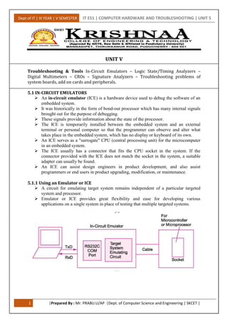
  • 1. Dept of IT | III YEAR | V SEMESTER IT E51 | COMPUTER HARDWARE AND TROUBLESHOOTING | UNIT 5 1 |Prepared By : Mr. PRABU.U/AP |Dept. of Computer Science and Engineering | SKCET | UNIT V Troubleshooting & Tools In-Circuit Emulators – Logic State/Timing Analyzers – Digital Multimeters – CROs – Signature Analyzers – Troubleshooting problems of system boards, add on cards and peripherals. 5.1 IN-CIRCUIT EMULATORS  An in-circuit emulator (ICE) is a hardware device used to debug the software of an embedded system.  It was historically in the form of bond-out processor which has many internal signals brought out for the purpose of debugging.  These signals provide information about the state of the processor.  The ICE is temporarily installed between the embedded system and an external terminal or personal computer so that the programmer can observe and alter what takes place in the embedded system, which has no display or keyboard of its own.  An ICE serves as a "surrogate" CPU (central processing unit) for the microcomputer in an embedded system.  The ICE usually has a connector that fits the CPU socket in the system. If the connector provided with the ICE does not match the socket in the system, a suitable adapter can usually be found.  An ICE can assist design engineers in product development, and also assist programmers or end users in product upgrading, modification, or maintenance. 5.1.1 Using an Emulator or ICE  A circuit for emulating target system remains independent of a particular targeted system and processor.  Emulator or ICE provides great flexibility and ease for developing various applications on a single system in place of testing that multiple targeted systems.
  • 2. Dept of IT | III YEAR | V SEMESTER IT E51 | COMPUTER HARDWARE AND TROUBLESHOOTING | UNIT 5 2 |Prepared By : Mr. PRABU.U/AP |Dept. of Computer Science and Engineering | SKCET | 5.1.2 Advantages  Virtually all embedded systems have a hardware element and a software element, which are separate but tightly interdependent.  The ICE allows the software element to be run and tested on the actual hardware on which it is to run, but still allows programmer conveniences to help isolate faulty code, such as "source-level debugging" (which shows the program the way the programmer wrote it) and single-stepping (which lets the programmer run the program step-by-step to find errors).  Most ICEs consist of an adaptor unit that sits between the ICE host computer and the system to be tested. A header and cable assembly connects the adaptor to a socket where the actual CPU or microcontroller mounts within the embedded system. 5.1.3 Function  The basic idea of an "in-circuit emulator" is that it provides a window into the embedded system.  The programmer uses the emulator to load programs into the embedded system, run them, step through them slowly, and see and change the data used by the system's software.  An "emulator" gets its name because it often "emulates" the central processing unit of the embedded system's computer.  Often, it literally has a plug that plugs into the same socket as the CPU chip. Emulating the main computer lets it do anything that the main computer can do, but under the control of a programmer.  ICEs are always tools that attach a terminal or PC to the embedded system. The terminal or PC provides an interactive user interface for the programmer to investigate and control the embedded system.  Notably, when their program fails, most embedded systems simply become inert lumps of nonfunctioning electronics.  Embedded systems often lack basic functions to detect signs of software failure, such as an MMU to catch memory access errors.  Without an ICE, the development of embedded systems can be extremely difficult, because there is usually no way to tell what went wrong.  With an ICE, the programmer can usually test pieces of code, then isolate the fault to a particular failing piece of code, and then inspect the failing code and rewrite it to solve the problem.  In usage, an ICE provides the programmer with execution breakpoints, memory display & monitoring, and input/output control. Beyond this, the ICE can be programmed to look for any range of matching criteria to pause at, hopefully catching the failure's origin. 5.1.4 Features of Emulators, Simulators, and In-Circuit Debuggers Parameters Software Simulation In-Circuit Simulation In-Circuit Emulator In-Circuit Debugger Real-time execution No No Yes Yes
  • 3. Dept of IT | III YEAR | V SEMESTER IT E51 | COMPUTER HARDWARE AND TROUBLESHOOTING | UNIT 5 3 |Prepared By : Mr. PRABU.U/AP |Dept. of Computer Science and Engineering | SKCET | Parameters Software Simulation In-Circuit Simulation In-Circuit Emulator In-Circuit Debugger Low cost Yes/Low/Free Yes/Low No/High Yes/Low Full device peripheral implementation No/Limited Yes/Limited Yes Yes Automatic download of new program Yes Yes Yes Yes No loss of target device I/O pins when debugging Yes/Sometimes Yes/Sometimes Yes No Target system cabling None Complex Complex Simple View and modify RAM and peripherals Yes Yes/Limited Yes Yes I/O resources needed to support debugging None Serial port, some I/O pins None Two or fewer I/O No loss of program memory or data RAM Yes No Yes No Simple connectivity of debugger to target None No/Complex No/Complex Yes Real-time trace buffer No/Limited No/Limited Yes No Single stepping Yes Yes Yes Yes Hardware breakpoints Yes/Unlimited One/Unlimited One/Unlimited Yes/One 5.2 LOGIC STATE/TIMING ANALYSERS  A logic analyzer is an electronic instrument that captures and displays multiple signals from a digital system or digital circuit.  A logic analyzer may convert the captured data into timing diagrams, protocol decodes, state machine traces, assembly language, or may correlate assembly with source-level software. Logic Analyzers have advanced triggering capabilities, and are useful when a user needs to see the timing relationships between many signals in a digital system  When logic analyzers first came into use, it was common to attach several hundred "clips" to a digital system. Later, specialized connectors came into use.
  • 4. Dept of IT | III YEAR | V SEMESTER IT E51 | COMPUTER HARDWARE AND TROUBLESHOOTING | UNIT 5 4 |Prepared By : Mr. PRABU.U/AP |Dept. of Computer Science and Engineering | SKCET |  The evolution of logic analyzer probes has led to a common footprint that multiple vendors support, which provides added freedom to end users. When to use a logic analyzer ?  When one wishes to observe many signals at the same time.  When it's necessary to look at signals in the system the same way hardware does.  When it's required to trigger on a pattern of highs and lows on several lines and see the results. 5.2.1 Logic analyser types  Modular logic analyzers : This type of logic analyser is probably what may be thought of as the most typical form of test instrument, although it is the highest cost option providing the highest level of functionality. It comprises a chassis and the various modules - including channel modules. The number of modules being larger for the higher channel counts.  Portable logic analyzers : In a number of instances there may be a need for a smaller analyser, possibly for restricted budgets or for field service. These test instruments incorporate all elements of the analyser into a single box for ease of transportation.  PC based logic analyzers: There is a growing number of PC based logic analysers. These consist of an analyser unit that is connected to a PC. USB is an obvious option for this, but Ethernet is also widely used because of its high speed. This form of PC based instrument uses the processing power of the PC combined with its display to reduce the cost of the overall system. 5.2.2 Uses  Many digital designs, including those of ICs, are simulated to detect defects before the unit is constructed.  The simulation usually provides logic analysis displays. Often, complex discrete logic is verified by simulating inputs and testing outputs using boundary scan.  Logic analyzers can uncover hardware defects that are not found in simulation.  These problems are typically too difficult to model in simulation, or too time consuming to simulate and often cross multiple clock domains. 5.2.3 Operation  A logic analyzer can trigger on a complicated sequence of digital events, and then capture a large amount of digital data from the system under test (SUT).  The best logic analyzers behave like software debuggers by showing the flow of the computer program and decoding protocols to show messages and violations.  When logic analyzers first came into use, it was common to attach several hundred "clips" to a digital system. Later, specialized connectors came into use.  The evolution of logic analyzer probe has led to a common footprint that multiple vendors support, which provides added freedom to end users.  Once the probes are connected, the user programs the analyzer with the names of each signal, and can group several signals into groups for easier manipulation.  Next, a capture mode is chosen, either timing mode, where the input signals are sampled at regular intervals based on an internal or external clock source, or state mode, where one or more of the signals are defined as "clocks," and data is
  • 5. Dept of IT | III YEAR | V SEMESTER IT E51 | COMPUTER HARDWARE AND TROUBLESHOOTING | UNIT 5 5 |Prepared By : Mr. PRABU.U/AP |Dept. of Computer Science and Engineering | SKCET | taken on the rising or falling edges of these clocks, optionally using other signals to qualify these clocks.  After the mode is chosen, a trigger condition must be set. A trigger condition can range from simple (such as triggering on a rising or falling edge of a single signal), to the very complex (such as configuring the analyzer to decode the higher levels of the TCP/IP stack and triggering on a certain HTTP packet).  At this point, the user sets the analyzer to "run" mode, either triggering once, or repeatedly triggering.  Once the data is captured, it can be displayed several ways, from the simple (showing waveforms or state listings) to the complex (showing decoded Ethernet protocol traffic).  The analyzer can also operate in a "compare" mode, where it compares each captured data set to a previously recorded data set, and stopping triggering when this data set is either matched or not.  This is useful for long-term empirical testing. Recent analyzers can even be set to email a copy of the test data to the engineer on a successful trigger. 5.3 MULTIMETER  A multimeter or a multitester is an electronic measuring instrument that combines several functions in one unit. The most basic instruments include an ammeter, voltmeter, and ohmmeter.  Analog multimeters are sometimes referred to as "volt-ohm-meters", abbreviated VOM.  Digital multimeters are usually referred to as "digital-multi-meters", abbreviated DMM.  A multimeter can be a handheld device useful for basic fault finding and field service work or a bench instrument which can measure to a very high degree of accuracy.  Such an instrument will commonly be found in a calibration lab and can be used to characterized resistance and voltage standards or adjust and verify the performance of multi-function calibrators. 5.3.1 A Digital Multimeter  Current, voltage, and resistance measurements are considered standard features for multimeters.  AVO multimeters, a manufacturer of early multimeters, derived their name from amperes, volts, and ohms, the units used for the measurement of current, voltage, and resistance.  Multimeters are available in a wide ranges of features and prices.  They are extremely handy devices to have around the house as they can be used to troubleshoot electrical problems in a wide array of household devices such as possibly dead batteries, washing and drying machines, kitchen appliances, and even automobile electronics and electrical systems.
  • 6. Dept of IT | III YEAR | V SEMESTER IT E51 | COMPUTER HARDWARE AND TROUBLESHOOTING | UNIT 5 6 |Prepared By : Mr. PRABU.U/AP |Dept. of Computer Science and Engineering | SKCET | 5.3.2 An Analog Multimeter Newer equipment can measure many other quantities. Some common additional measured quantities and the units in which they are measured:  Inductance in henrys.  Capacitance in farads.  Conductance in siemens.  Temperature in degrees Celsius or Fahrenheit.  Frequency in hertz.  Duty cycle as a percentage. A multimeter may be implemented with an analog meter deflected by an electromagnet, as a classic galvanometer; or with a digital display such as an LCD or Vacuum fluorescent display. Analog multimeters are not hard to find in the used market, but are not very accurate because of errors introduced in zeroing and reading the analog meter face. Analog meters may be implemented with vacuum tubes to precondition and amplify the input signal. Such meters are known as vacuum tube volt meters (VTVM) or vacuum tube multimeters (VTMM). 5.3.3 Resolution The resolution of a multimeter is often specified in "digits" of resolution. The term "digits" dates back to the 1970's when multimeter vendors were very proud of how many digits their products could display.  A 5½ digit multimeter would have five full digits that display values from 0 to 9 and one half digit that could only display 0 or 1.  This digital multimeter could show positive or negative values from 0 to 199,999.  For a modern DMM, such as a PC-based multimeter, the term "digits" actual maps to the noise performance of the device. 5.3.4 Common Features  Modern multimeters are exclusively digital, and identified by the term DMM or digital multimeter.  In such an instrument, the signal under test is converted to a digital voltage and an amplifier with an electronically controlled gain preconditions the signal.  Similarly, better circuitry and electronics have improved meter accuracy. Older analog meters might have basic accuracies of five to ten percent.  Modern portable DMMs may have accuracies as good as ±0.025%, and bench-top instruments have accuracies in the single-digit parts per million figures. 5.3.5 Commonly Available Measurement Enhancements  Current-limited tests for voltage drop across semiconductor junctions. While not a replacement for a transistor tester, this facilitates testing diodes and a variety of transistor types.  A graphic representation of the quantity under test, as a bar graph. This makes go/no-go testing easy.  A continuity tester that beeps when a circuit conducts.  A low-bandwidth oscilloscope.  A telephone test set.
  • 7. Dept of IT | III YEAR | V SEMESTER IT E51 | COMPUTER HARDWARE AND TROUBLESHOOTING | UNIT 5 7 |Prepared By : Mr. PRABU.U/AP |Dept. of Computer Science and Engineering | SKCET |  Automotive circuit testers, including tests for automotive timing and dwell signals.  Simple data acquisition features to record maximum and minimum readings over a given period, or to take a number of samples at fixed intervals.  Sample and hold, which will latch the most recent reading for examination after the instrument is removed from the circuit under test. 5.3.6 Probes  A multimeter can utilize a variety of test probes to connect to the circuit or device under test.  Crocodile clips, retractable hook clips, and pointed probes are the three most common attachments.  The connectors are attached to flexible, thickly-insulated leads that are terminated with connectors appropriate for the meter.  Handheld meters typically use shrouded or recessed banana jacks, while bench top meters may use banana jacks or BNC connectors. 5.4 CATHODE-RAY OSCILLOSCOPE (CRO)  The Cathode-Ray Oscilloscope (CRO) is a common laboratory instrument that provides accurate time and amplitude measurements of voltage signals over a wide range of frequencies. Its reliability, stability, and ease of operation make it suitable as a general purpose laboratory instrument.  The Cathode Ray Oscilloscope consists of Cathode-ray tube , timebase circuit , vertical amplifier, trigger circuit and power supply as shown in the block diagram of CRO. 5.4.1 Block diagram of CRO:
  • 8. Dept of IT | III YEAR | V SEMESTER IT E51 | COMPUTER HARDWARE AND TROUBLESHOOTING | UNIT 5 8 |Prepared By : Mr. PRABU.U/AP |Dept. of Computer Science and Engineering | SKCET | 5.4.2 Cathode-ray Tube: Main part Component Function Filament When a current passes through the filament, the filament becomes hot and heats up the cathode. Cathode Emits electrons when it is hot. Control Grid  Control the number of electrons hitting the fluorescent screen.  Control the brightness of the spot on the screen. Focusing Anode To focus the electrons onto the screen. Accelerating Anode To accelerate the electrons to high speed. Y-Plates To deflect the electron beam vertically. X-Plates To deflect the electron beam horizontally. Glass surface coated with a fluorescent material. To convert the kinetic energy of the electrons to heat and light energy when the electrons hit the screen. Electron gun Deflecting system Fluorescent screen
  • 9. Dept of IT | III YEAR | V SEMESTER IT E51 | COMPUTER HARDWARE AND TROUBLESHOOTING | UNIT 5 9 |Prepared By : Mr. PRABU.U/AP |Dept. of Computer Science and Engineering | SKCET | 5.4.3 Description:  The interior of the Cathode ray tube is a very good vacuum, with a pressure of around 0.01 Pa (10−7 atm) or less.  At pressure, collisions of electrons with air molecules would scatter the electron beam excessively.  The cathode, at the left end in the figure, is raised to a high temperature by the heater, and electrons evaporate from the surface of the cathode. 5.4.4 CRO Operation:  The cathode ray is a beam of electrons which are emitted by the heated cathode (negative electrode) and accelerated toward the fluorescent screen.  The assembly of the cathode, intensity grid, focus grid, and accelerating anode (positive electrode) is called an electron gun. Its purpose is to generate the electron beam and control its intensity and focus.  Between the electron gun and the fluorescent screen are two pair of metal plates - one oriented to provide horizontal deflection of the beam and one pair oriented to give vertical deflection to the beam.  These plates are thus referred to as the horizontal and vertical deflection plates.  The combination of these two deflections allows the beam to reach any portion of the fluorescent screen.  Wherever the electron beam hits the screen, the phosphor is excited and light is emitted from that point.  This conversion of electron energy into light allows us to write with points or lines of light on an otherwise darkened screen. 5.4.5 Features and Uses 1. Exterior  A typical oscilloscope is usually box shaped with a display screen, numerous input connectors, control knobs and buttons on the front panel.  To aid measurement, a grid called the graticule is drawn on the face of the screen. Each square in the graticule is known as a division. 2. Inputs  The signal to be measured is fed to one of the input connectors, which is usually a coaxial connector such as a BNC or N type  If the signal source has its own coaxial connector, then a simple coaxial cable is used; otherwise, a specialized cable called a 'scope probe', supplied with the oscilloscope is used. 3. The trace  In its simplest mode, the oscilloscope repeatedly draws a horizontal line called the trace across the middle of the screen from left to right.  One of the controls, the time base control, sets the speed at which the line is drawn, and is calibrated in seconds per division.  If the input voltage departs from zero, the trace is deflected either upwards or downwards.
  • 10. Dept of IT | III YEAR | V SEMESTER IT E51 | COMPUTER HARDWARE AND TROUBLESHOOTING | UNIT 5 10 |Prepared By : Mr. PRABU.U/AP |Dept. of Computer Science and Engineering | SKCET | 4. Trigger  To provide a more stable trace, modern oscilloscopes have a function called the trigger. When using triggering, the scope will pause each time the sweep reaches the extreme right side of the screen.  The scope then waits for a specified event before drawing the next trace.  The trigger event is usually the input waveform reaching some user-specified threshold voltage in the specified direction (going positive or going negative). 5.4.6 Types of Trigger  External trigger, a pulse from an external source connected to a dedicated input on the scope.  Edge trigger, an edge-detector that generates a pulse when the input signal crosses a specified threshold voltage in a specified direction.  Video trigger, a circuit that extracts synchronising pulses from video formats such as PAL and NTSC and triggers the timebase on every line, a specified line, every field, or every frame. This circuit is typically found in a waveform monitor device.  Delayed trigger, which waits a specified time after an edge trigger before starting the sweep. No trigger circuit acts instantaneously, so there is always a certain delay, but a trigger delay circuit extends this delay to a known and adjustable interval. In this way, the operator can examine a particular pulse in a long train of pulses. 5.5 SIGNATURE ANALYSERS Signature Analysis is an easy-to-use and highly accurate technique for identifying faulty logic nodes.  It is one specialized class of test instruments used in product development, production, and field services.  It can be very effective in troubleshooting microprocessor systems by converting serial data, streams present on microprocessor system logic nodes into four-digit “signatures” and these signatures tell whether or not the nodes is performing properly. 5.5.1 Function of Signature analyzer  Signature analyzer is a pattern detector.  Signature analyzer can detect what activities occur more than once, and calls them patterns.  These patterns can be detected from text input, MIDI code input and analogue x,y,z input.  Signature database puts every pattern found in a database containing:  A pointer to the particular sensor(s).  Time stamps of the starting points of these activities.  Number of reoccurrences of a pattern ("frequency").  Length of each pattern.  Impact of any pattern (= freq times length of a pattern). Analysis afterwards can compute the impact of a pattern as a percentage of the whole session.  Anything more if necessary.
  • 11. Dept of IT | III YEAR | V SEMESTER IT E51 | COMPUTER HARDWARE AND TROUBLESHOOTING | UNIT 5 11 |Prepared By : Mr. PRABU.U/AP |Dept. of Computer Science and Engineering | SKCET | 5.5.2 HP 5004A model Signature analyser interprets incoming data as background noise and detects reoccurrences as an argument to find any identifiable object. The reoccurrence itself identifies the object by pointing at the other occurrence.  Signature analyser transforms noise to objects in an unsupervised manner.  Signature analyser detects patterns in different hierarchical levels.  Signature database can be used to give names to patterns like: walking, standing up, jumping etc. (supervised learning). 5.6 TROUBLESHOOTING PROBLEMS OF SYSTEM BOARDS, ADD ON CARDS AND PERIPHERALS. More than 70% of all computer problems are related to cabling and connections. Ensure all cables are connected and connected firmly. IDE and floppy ribbon cables and power cables can often go loose. Ensure microprocessor, memory modules, and adapters such as video card are inserted correctly and didn't "pop-up" due to vibration. How to troubleshoot a Windows PC Motherboard? Operating System will not load? Reseat RAM - if multiple SIMMS (single inline memory modules) or DIMMS (dual inline memory modules) then remove them all and replace and test individually. Did you install after market RAM? Is it compatible? Is it sequenced correctly - must be in pairs? Is it the correct amount of RAM?  POST Codes (Power On Self Test) - Computer Beeps at start up - Reseat the PCI cards. For notebooks then reseat the mini-PCI bus. Reseat the RAM.  For Notebooks - perform a hard reset.  Perform Diagnostics test.  Perform an MSCONFIG if your computer has it.  Shut down all other applications to avoid conflicts. Remove all other hardware devices.  Perform a recovery. Ensure that you backup your data prior to doing a recovery.  If the problem persists then send in for service.  Check error messages in Event Viewer. Start / Settings / Control Panel / Administrative Tools / Computer Management (or Event Viewer)  CPU Heat - check to ensure that there is proper ventilation and the fan is working. For notebook heat issues - use SPEEDSTEP (Intel) to the lower the cycle speed (megahertz). Enable Battery Optimized Performance. Was your CPU replaced? Was the thermal barrier replaced correctly. The CPU must be sealed correctly with a thermal barrier (adhesive between CPU and motherboard) or it could cause heat problems.  Conflicts in system devices - check the IRQ (Interrupt Requests 0-15) in the BIOS and reset the BIOS. System has no power at all. Power light does not illuminate, fan inside the power supply does not turn on, and indicator light on keyboard does not turn on. PROBABLE CAUSE DIAGNOSIS SOLUTION Power cable is unplugged. Visually inspect power cable. Make sure power cable is securely plugged in. Defective power cable. Visual inspection, try another cable. Replace cable.
  • 12. Dept of IT | III YEAR | V SEMESTER IT E51 | COMPUTER HARDWARE AND TROUBLESHOOTING | UNIT 5 12 |Prepared By : Mr. PRABU.U/AP |Dept. of Computer Science and Engineering | SKCET | Power supply failure. Power cable and wall socket are OK, but system is still dead. Contact technical support Faulty wall outlet; circuit breaker or fuse blown. Plug device into socket know to work and test. Use different socket, repair outlet, reset circuit breaker or replace fuse. System inoperative. Keyboard lights are on, power indicator lights are lit, and hard drive is spinning. PROBABLE CAUSE DIAGNOSIS SOLUTION Expansion card is partially dislodged from expansion slot on the motherboard. Turn off computer. Take cover off system unit. Check all expansion cards to ensure they are securely seated in slots. Using even pressure on both ends of the expansion card, press down firmly on expansion card. Defective floppy disk drive or tape drive. Turn system off. Disconnect the cables from one of the floppy drives. Turn on the system, check to see if the keyboard operates normally. Repeat until you have located defective unit. Contact Technical Support. Defective expansion card. Turn computer off. Remove an expansion card. Make sure expansion card is secure in expansion socket. System does not boot from hard disk drive, can be booted from floppy disk drive. PROBABLE CAUSE DIAGNOSIS SOLUTION Connector between hard drive and system board unplugged. When attempting to run the FDISK utility described in the HARD DISK section of the manual you get a message, INVALID DRIVE SPECIFICATION. Check cable running form disk to disk controller on the board. Make sure both ends are securely plugged in; check the drive type in the Standard CMOS Setup (in your motherboard manual). Damaged Hard Disk or Disk Controller. Format hard disk; if unable to do so, the hard disk may be defective. Contact Technical Support. Hard Disk directory or FAT is scrambled. Run the FDISK program, format the hard drive(See HARD DRIVE section of manual). Copy your backup data back onto hard drive. Backing up the hard drive is extremely important. All Hard Disks are capable of breaking down at any time.
  • 13. Dept of IT | III YEAR | V SEMESTER IT E51 | COMPUTER HARDWARE AND TROUBLESHOOTING | UNIT 5 13 |Prepared By : Mr. PRABU.U/AP |Dept. of Computer Science and Engineering | SKCET | System only boots from Floppy Disk. Hard Disk can be read and applications can be used, but booting from Hard Disk is impossible. PROBABLE CAUSE DIAGNOSIS SOLUTION Hard Disk boot program has been destroyed. A number of causes could be behind this. Back up data and applications files. Reformat the Hard Drive as described in the Hard Drive section of the manual. Re- install applications and data using backup disks. Error message reading "SECTOR NOT FOUND" or other error messages indication certain data is not allowed to be retrieved. PROBABLE CAUSE DIAGNOSIS SOLUTION A number of causes could be behind this. Use a file by file backup instead of an image backup to backup the Hard Disk. Back up any salvageable data. Then do a low level format, partition, and high level format of the hard drive( see Hard Disk section of your manual for instructions). Re-install all saved data when completed. Disk formatted on IBM PS/2 will not operate with this system. PROBABLE CAUSE DIAGNOSIS SOLUTION The IBM PS/2 uses a different format than other computers. IBM PS/2 disk format will not work in an AT type computer. Format disk in the AT type computer insert disk into the IBM PS/2 and copy the files you wish. After install an expansion card (network card, tape drive card, etc.) the system no longer works properly. PROBABLE CAUSE DIAGNOSIS SOLUTION No power to monitor. All or part of the system may be inoperable. The new card may work but a mouse or COM port may not work. Change the interrupt or RAM address on the new expansion card. See the documentation that came with the new card in order to change pin settings. many expansion devices come with proprietary software that will assist you in doing this.
  • 14. Dept of IT | III YEAR | V SEMESTER IT E51 | COMPUTER HARDWARE AND TROUBLESHOOTING | UNIT 5 14 |Prepared By : Mr. PRABU.U/AP |Dept. of Computer Science and Engineering | SKCET | Screen message says "Invalid Configuration" or "CMOS Failure." PROBABLE CAUSE DIAGNOSIS SOLUTION Incorrect information entered into the configuration (setup) program. Check the configuration program. Replace any incorrect information. Review system's equipment. Make sure correct information is in setup. Screen is blank. PROBABLE CAUSE DIAGNOSIS SOLUTION No power to monitor. Power connectors may be loose or not plugged in. Check the power connectors to monitor and to system. Make sure monitor is connected to display card, change I/O address on network card if applicable. Monitor not connected to computer. See instructions above. Network card I/O address conflict. See instructions above. System does not boot from hard disk drive, can be booted from floppy disk drive. PROBABLE CAUSE DIAGNOSIS SOLUTION Connector between hard drive and system board unplugged. When attempting to run the FDISK utility described in the HARD DISK section of the manual you get a message, INVALID DRIVE SPECIFICATION. Check cable running form disk to disk controller on the board. Make sure both ends are securely plugged in; check the drive type in the Standard CMOS Setup (in your Problem PROBABLE CAUSE DIAGNOSIS SOLUTION Memory problem, display card jumpers not set correctly. Reboot computer. Re-install memory, make sure that all memory modules are installed in correct sockets. Check jumper and switch settings on display card. See display card section for information of settings. Computer virus. Use anti-virus programs (McAfee/PC-cillin, E-port, etc) to detect and clean viruses.
  • 15. Dept of IT | III YEAR | V SEMESTER IT E51 | COMPUTER HARDWARE AND TROUBLESHOOTING | UNIT 5 15 |Prepared By : Mr. PRABU.U/AP |Dept. of Computer Science and Engineering | SKCET | Screen goes blank periodically. PROBABLE CAUSE DIAGNOSIS SOLUTION Screen saver is enabled. Disable screen saver. Keyboard failure. PROBABLE CAUSE DIAGNOSIS SOLUTION Keyboard is disconnected. Reconnect keyboard. Check keys again, if no improvement, replace keyboard. No color on screen. PROBABLE CAUSE DIAGNOSIS SOLUTION Faulty Monitor. If possible, connect monitor to another system. If no color, replace monitor. CMOS incorrectly set up. Call technical support. Floppy drive lights stays on. PROBABLE CAUSE DIAGNOSIS SOLUTION Floppy Drive cable not connected correctly. Reconnect floppy cable making sure PIN1 on the Floppy Drive corresponds with PIN1 on floppy cable connector. Error reading drive A: PROBABLE CAUSE DIAGNOSIS SOLUTION Bad floppy disk. Try new floppy disk. Floppy disk not formatted Format floppy disk(type ENTER) C: drive failure. PROBABLE CAUSE DIAGNOSIS SOLUTION SETUP program does not have correct information. Boot from drive A: using DOS system disk. Input correct information to SETUP program. Hard Drive cable not connected properly. Check Hard drive cable.
  • 16. Dept of IT | III YEAR | V SEMESTER IT E51 | COMPUTER HARDWARE AND TROUBLESHOOTING | UNIT 5 16 |Prepared By : Mr. PRABU.U/AP |Dept. of Computer Science and Engineering | SKCET | Cannot boot system after installing second hard drive. PROBABLE CAUSE DIAGNOSIS SOLUTION Master/Slave jumpers not set correctly. Set master /Slave jumpers correctly. Hard Drives not compatible / different manufacturers. Run SETUP program and select correct drive types. Call drive manufactures for compatibility with other drives. Missing operating system on hard drive. PROBABLE CAUSE DIAGNOSIS SOLUTION CMOS setup has been changed. Run setup and select correct drive type. Certain keys do not function. PROBABLE CAUSE DIAGNOSIS SOLUTION Keys jammed or defective. Replace keyboard. Keyboard is locked, no keys function. PROBABLE CAUSE DIAGNOSIS SOLUTION Keyboard is locked. Unlock keyboard