SlideShare ist ein Scribd-Unternehmen logo
1 von 31
B.Prabhu kiran (11621A0407) AEC, Bhongir
~ 1 ~
1. INTRODUCTION
In simple terms, Li-Fi can be thought of as a light-based Wi-Fi. That is, it uses light
instead of radio waves to transmit information. And instead of Wi-Fi modems, Li-Fi would
use transceiver-fitted LED lamps that can light a room as well as transmit and receive
information. Since simple light bulbs are used, there can technically be any number of
access points.
This technology uses a part of the electromagnetic spectrum that is still not greatly
utilized- The Visible Spectrum. Light is in fact very much part of our lives for millions and
millions of years and does not have any major ill effect. Moreover there is 10,000 times
more space available in this spectrum and just counting on the bulbs in use, it also multiplies
to 10,000 times more availability as an infrastructure, globally. It is possible to encode data
in the light by varying the rate at which the LEDs flicker on and off to give different strings
of 1s and 0s. The LED intensity is modulated so rapidly that human eyes cannot notice, so
the output appears constant.
More sophisticated techniques could dramatically increase VLC data rates. Teams at
the University of Oxford and the University of Edinburgh are focusing on parallel data
transmission using arrays of LEDs, where each LED transmits a different data stream. Other
groups are using mixtures of red, green and blue LEDs to alter the light's frequency, with
each frequency encoding a different data channel.
Li-Fi, as it has been dubbed, has already achieved blisteringly high speeds in the lab.
Researchers at the Heinrich Hertz Institute in Berlin, Germany, have reached data rates of
over 500 megabytes per second using a standard white-light LED. Haas has set up a spin-off
firm to sell a consumer VLC transmitter that is due for launch next year. It is capable of
transmitting data at 100 MB/s - faster than most UK broadband connections.
Li-fi is transmission of data through illumination by taking the fibre out of fibre optics by
sending data through a LED light bulb that varies in intensity faster than the human eye can
follow. Li-Fi is the term some have used to label the fast and cheap wireless communication
system, which is the optical version of Wi-Fi. The term was first used in this context by
Harald Haas in his TED Global talk on Visible Light Communication. “At the heart of this
B.Prabhu kiran (11621A0407) AEC, Bhongir
~ 2 ~
technology is a new generation of high brightness light-emitting diodes”, says Harald Haas
from the University of Edinburgh, UK. Simply, if the LED is on, it transmits a digital 1, if
it’s off it transmits a 0. Haas says, “They can be switched on and off very quickly, which
gives nice opportunities for transmitted data.” It is possible to encode data in the light by
varying the rate at which the LEDs flicker on and off to give different strings of 1s and 0s.
The LED intensity is modulated so rapidly that human eye cannot notice, so the output
appears constant. More sophisticated techniques could dramatically increase VLC data rate.
Terms at the University of Oxford and the University of Edinburgh are focusing on parallel
data transmission using array of LEDs, where each LED transmits a different data stream.
Other groups are using mixtures of red, green and blue LEDs to alter the light frequency
encoding a different data channel. Li-Fi, as it has been dubbed, has already achieved
blisteringly high speed in the lab. Researchers at the Heinrich Hertz Institute in Berlin,
Germany have reached data rates of over 500 megabytes per second using a standard white-
light LED. The technology was demonstrated at the 2012 Consumer Electronics Show in
Las Vegas using a pair of Casio smart phones to exchange data using light of varying
intensity given off from their screens, detectable at a distance of up to ten meters.
The general term visible light communication (VLC), includes any use of the visible
light portion of the electromagnetic spectrum to transmit information. The D-Light project
at Edinburgh's Institute for Digital Communications was funded from January 2010 to
January 2012. Haas promoted this technology in his 2011 TED Global talk and helped start
a company to market it. PureLiFi, formerly pureVLC, is an original equipment
manufacturer (OEM) firm set up to commercialize Li-Fi products for integration with
existing LED-lighting systems.
In October 2011 a number of companies and industry groups formed the Li-Fi
Consortium, to promote high-speed optical wireless systems and to overcome the limited
amount of radio based wireless spectrum available by exploiting a completely different part
of the electromagnetic spectrum. The consortium believes it is possible to achieve more than
10 Gbps, theoretically allowing a high-definition film to be downloaded in 30 seconds
B.Prabhu kiran (11621A0407) AEC, Bhongir
~ 3 ~
Fig. 1.1 Li-Fi Environment
B.Prabhu kiran (11621A0407) AEC, Bhongir
~ 4 ~
2. HISTORY OF LI-FI
2.1 The need for Visible Light Communication (VLC)
Issues regarding Radio Waves:
1. Capacity:
 Radio waves are limited, scar and expensive. We only have a certain range of it.
 With the advent of the new generation technologies as of likes of 2.5G, 3G, 4G
and so on we are running out of spectrum.
2. Efficiency:
 There are 1.4 million cellular radio base stations. They consume massive amount
of energy.
 Most of this energy is not used for transmission but for cooling down the base
stations.
 Efficiency of such a base station is only 5% and that raise a very big problem.
3. Availability:
 We have to switch off our mobiles in aero planes.
 It is not advisable to use mobiles at places like petrochemical plants and petrol
pumps.
 Availability of radio waves causes another concern.
4. Security:
 Radio waves penetrate through walls.
 They can be intercepted. If someone has knowledge and bad intentions then he
may misuse it.
So we should look for other parts of EM waves.
Gamma rays are simply very dangerous and thus can’t be used for our purpose of
communication. X-rays are good in hospital and can’t be used either. Ultra-violet rays are
sometimes good for our skin but for long duration it is dangerous. Infra-red rays are bad for
our eyes and are therefore used at low power levels. We have already seen shortcomings of
radio waves. So we are left with only Visible light spectrum.
B.Prabhu kiran (11621A0407) AEC, Bhongir
~ 5 ~
Fig. 2.1 issues regarding Radio spectrum
2.2 Genesis of Li-Fi
Harald Haas, a professor at the University of Edinburgh who began his research in
the field in 2004, gave a debut demonstration of what he called a Li-Fi prototype at the TED
Global conference in Edinburgh on 12th July 2011. He coined the term Li-Fi and is widely
recognized as the original founder of Li-Fi. He is Chairman of Mobile Communications at
the University of Edinburgh and co-founder of pureLiFi.
Haas used a table lamp with an LED bulb to transmit a video of blooming flowers
that was then projected onto a screen behind him. During the event he periodically blocked
the light from lamp to prove that the lamp was indeed the source of incoming data. At TED
Global, Haas demonstrated a data rate of transmission of around 10Mbps -- comparable to a
fairly good UK broadband connection. Two months later he achieved 123Mbps. In 2011
German scientists succeeded in creating an800Mbps (Megabits per second) capable wireless
network by using nothing more than normal red, blue, green and white LED light bulbs
B.Prabhu kiran (11621A0407) AEC, Bhongir
~ 6 ~
(here), thus the idea has been around for awhile and various other global teams are also
exploring the possibilities.
VLC technology was exhibited in 2012 using Li-Fi. By August 2013, data rates of
over 1.6 Gbit/s were demonstrated over a single color LED. In September 2013, a press
release said that Li-Fi, or VLC systems in general, do not require line-of-sight conditions.
One part of VLC is modeled after communication protocols established by
the IEEE workgroup. However, the IEEE 802.15.7 standard is out-of-date. Specifically, the
standard fails to consider the latest technological developments in the field of optical
wireless communications, specifically with the introduction of optical orthogonal
frequency-division multiplexing (O-OFDM) modulation methods which have been
optimized for data rates, multiple-access and energy efficiency have. The introduction of O-
OFDM means that a new drive for standardization of optical wireless communications is
required.
Nonetheless, the IEEE 802.15.7 standard defines the physical layer (PHY)
and media access control (MAC) layer. The standard is able to deliver enough data rates to
transmit audio, video and multimedia services. It takes into account the optical transmission
mobility, its compatibility with artificial lighting present in infrastructures, the deviance
which may be caused by interference generated by the ambient lighting. The MAC layer
allows to use the link with the other layers like the TCP/IP protocol.
The standard defines three PHY layers with different rates:
 The PHY I was established for outdoor application and works from 11.67 Kbit/s to
267.6 Kbit/s.
 The PHY II layer allows reaching data rates from 1.25 Mbit/s to 96 Mbit/s.
 The PHY III is used for many emissions sources with a particular modulation method
called colour shift keying (CSK). PHY III can deliver rates from 12 Mbit/s to 96 Mbit/s.
The modulation formats recognized for PHY I and PHY II are the coding on-off
keying (OOK) and variable pulse position modulation (VPPM). The Manchester
coding used for the PHY I and PHY II layers include the clock inside the transmitted data
by representing a logic 0 with an OOK symbol "01" and a logic 1 with an OOK symbol
B.Prabhu kiran (11621A0407) AEC, Bhongir
~ 7 ~
"10", all with a DC component. The DC component avoids the light extinction in case of an
extended line of logic 0.
VLC technology is ready to use right now; it's being installed in museums and
businesses across France, and is being embraced by EDF, one of the nation's largest utilities.
Fig.2.2 Prof. Harald Hass
B.Prabhu kiran (11621A0407) AEC, Bhongir
~ 8 ~
3. WORKING PRINCIPLES
Li-Fi is typically implemented using white LED light bulbs at the downlink
transmitter. These devices are normally used for illumination only by applying a constant
current. But unlike other light sources LEDs can turn on & off millions of times per second.
However, by fast and subtle variations of the current, the optical output can be made to vary
at extremely high speeds. This very property of optical current is used in Li-Fi setup. The
operational procedure is very simple. If the LED is on, it transmits a digital 1, if it’s off it
transmits a 0. The LEDs can be switched on and off very quickly, which gives nice
opportunities for transmitting data. Hence all that is required is some LEDs and a controller
that code data into those LEDs. All one has to do is to vary the rate at which the LED’s
flicker depending upon the data we want to encode. Further enhancements can be made in
this method, like using an array of LEDs for parallel data transmission, or using mixtures of
red, green and blue LEDs to alter the light’s frequency with each frequency encoding a
different data channel. Such advancements promise a theoretical speed of 10 Gbps –
meaning one can download a full high-definition film in just 30 seconds.
Fig.3.1 Block Diagram of LI-FI
B.Prabhu kiran (11621A0407) AEC, Bhongir
~ 9 ~
To further get a grasp of Li-Fi consider an IR remote. It sends a single data stream of
bits at the rate of 10,000-20,000 bps. Now replace the IR LED with a Light Box containing
a large LED array. This system is capable of sending thousands of such streams at very fast
rate. Light is inherently safe and can be used in places where radio frequency
communication is often deemed problematic, such as in aircraft cabins or hospitals. So
visible light communication not only has the potential to solve the problem of lack of
spectrum space, but can also enable novel application. The visible light spectrum is unused;
it's not regulated, and can be used for communication at very high speed.
3.1 Visible light communication (VLC): A potential solution to the global
wireless spectrum shortage
Li-fi (Light Fidelity) is a fast and cheap optical version of Wi-Fi, the technology of
which is based on Visible Light Communication (VLC).VLC is a data communication
medium, which uses visible light between 400 THz (780 nm) and 800 THz (375 nm) as
optical carrier for data transmission and illumination. It uses fast pulses of light to transmit
information wirelessly. The main components of this communication system are
1. A high brightness white LED, which acts as a communication source and
2. A silicon photodiode
Which shows good response to visible wavelength region serving as the receiving
element? LED can be switched on and off to generate digital strings of 1s and 0s. Data can
be encoded in the light to generate a new data stream by varying the flickering rate of the
LED. To be clearer, by modulating the LED light with the data signal, the LED illumination
can be used as a communication source.
Due to the physical properties of these components, information can only be
encoded in the intensity of the emitted light, while the actual phase and amplitude of the
light wave cannot be modulated. This significantly differentiates VLC from RF
communications.VLC can only be realized as an IM/DD system, which means that the
modulation signal has to be both real valued and unipolar. This limits the application of the
well-researched and developed modulation schemes from the field of RF communications.
Techniques such as on-off keying (OOK), pulse-position modulation (PPM), pulse-width
B.Prabhu kiran (11621A0407) AEC, Bhongir
~ 10 ~
modulation (PWM) and unipolar M-ary pulse-amplitude modulation (M-PAM) can be
applied in a relatively straightforward fashion. As the modulation speeds are increased,
however, these particular modulation schemes begin to suffer from the undesired effects of
intersymbol interference (ISI) due to the non-flat frequency response of the optical wireless
communication channel. Hence, a more resilient technique such as OFDM is required.
OFDM allows adaptive bit and energy loading of different frequency sub-bands according
to the communication channel properties. This leads to optimal utilization of the available
resources. OFDM achieves the throughput capacity in a non-flat communication channel
even in the presence of nonlinear distortion. Such channel conditions are introduced by the
transfer characteristic of an off-the-shelf LED that has a maximum 3 dB modulation
bandwidth in the order of 20 MHz In fact, the record-breaking results have all been
achieved using OFDM. Further benefits of this modulation scheme include simple
equalization with single-tap equalizers in the frequency domain as well as the ability to
avoid low-frequency distortion caused by flickering background radiation and the baseline
wander effect in electrical circuits.
Conventional OFDM signals are complex-valued and bipolar in nature. Therefore,
the standard RF OFDM technique has to be modified in order to become suitable for IM/DD
systems. A straightforward way to obtain a real-valued OFDM signal is to impose a
Hermitian symmetry constraint on the sub-carriers in the frequency domain. However, the
resulting time-domain signal is still bipolar. One way for obtaining a unipolar signal is to
introduce a positive direct current (DC) bias around which the amplitude of the OFDM
signal can vary as shown in Figure.
(a) Unbiased bipolar OFDM signal (b) Biased unipolar OFDM signal
Fig.3.2
B.Prabhu kiran (11621A0407) AEC, Bhongir
~ 11 ~
The resulting unipolar modulation scheme is known as DC-biased optical OFDM
(DCO-OFDM). The addition of the constant biasing level leads to a significant increase in
electrical energy consumption. This can be easily visualized when Fig 3-2 (a) and Fig 3-2(b)
are juxtaposed. However, if the light sources are used for illumination at the same time, the
light output as a result of the DC bias is not wasted as it is used to fulfil the illumination
function. Only if illumination is not required, such as in the uplink of a Li-Fi system, the DC
bias can significantly compromise energy efficiency. Therefore, researchers have devoted
significant efforts to designing an OFDM-based modulation scheme which is purely
unipolar. Some well-known solutions include: asymmetrically clipped optical OFDM
(ACO-OFDM), pulse-amplitude-modulated discrete multi-tone modulation (PAM-DMT),
unipolar OFDM (U-OFDM), Flip-OFDM, spectrally-factorized optical OFDM (SFO-
OFDM). The general disadvantage of all these techniques is a 50% loss in spectral
efficiency, i.e., the data rates are halved. This limitation has recently been overcome by
researchers at the University of Edinburgh.
3.1.1 Multiple accesses using VLC
A networking solution cannot be realized without a suitable multiple access scheme
that allows multiple users to share the communication resources without any mutual cross-
talk. Multiple access schemes used in RF communications can be adapted for VLC as long
as the necessary modifications related to the IM/DD nature of the modulation signals are
performed. OFDM comes with a natural extension for multiple accesses – OFDMA. Single-
carrier modulation schemes such as M-PAM, OOK and PWM require an additional multiple
access technique such as frequency division multiple access (FDMA), time division
multiple access (TDMA) and/or code division multiple access (CDMA). The results of an
investigation regarding the performance of OFDMA versus TDMA and CDMA are
presented in Fig 3-3. FDMA has not been considered due to its close similarity to OFDMA,
and the fact that OWC does not use super heterodyning. In addition, due to the limited
modulation bandwidth of the front-end elements, this scheme would not present a very
efficient use of the LED modulation bandwidth.
B.Prabhu kiran (11621A0407) AEC, Bhongir
~ 12 ~
Fig 3.3. TDMA vs. OFDMA vs. CDMA (with optical orthogonal code) in a six-user
scenario)
As shown in Fig. 3-3, CDMA is very inefficient as the use of unipolar signals creates
significant interchannel interference (ICI) and a substantial increase in the power
requirements compared to its application in RF communications. At the same time, the
performance of TDMA barely surpasses that of OFDMA for the different scenarios. The
higher power requirement of OFDMA compared to TDMA is caused by its wider time-
domain signal distribution. This leads to the need for higher DC biasing levels and as a
consequence to higher power consumption which is reflected in the shown signal-to-noise
ratio (SNR). In a practical scenario where the functions of communication and illumination
are combined, the difference in power consumption between the different schemes would
diminish as the excess power due to the DC bias would be used for illumination purposes. It
should be pointed out that this investigation has been performed for a flat linear additive
white Gaussian noise (AWGN) channel where only clipping effects from below, applicable
only to OFDMA, have been considered. This is due to the fact that nonlinear effects such as
clipping from above as well as the nonlinear relationship between the modulating current
signal and the emitted optical signal are device-specific, while clipping from below is
inherent to any IM/DD system. Furthermore, low-frequency distortion effects from the DC-
wander in electrical components as well as from the flickering of background light sources
are also not considered. In a practical scenario, these effects would not be an issue for
OFDMA, but are expected to decrease the performance of TDMA and CDMA. Therefore,
B.Prabhu kiran (11621A0407) AEC, Bhongir
~ 13 ~
the design complexity of a TDMA or CDMA system increases as suitable techniques to deal
with these problems need to be implemented. It is also worth noting that the non-flatness of
the channel in a practical scenario would further degrade the performances of CDMA and
TDMA compared to OFDMA.
In VLC there exists an additional alternative dimension for achieving multiple
accesses. This is colour, and the corresponding technique is wavelength division multiple
access (WDMA). WDMA harnesses the different light wavelengths to facilitate multiple-
user access. This scheme could reduce the complexity in terms of signal processing.
However, it would lead to increased hardware complexity as well as to the need at each
access point for multiple transmitter elements with narrow wavelength emission. This
immediately puts strict requirements on the optical front-end elements, and compromises
SNR and, hence, capacity. In addition, WDMA excludes the usage of a large variety of off-
the-shelf LEDs as most of them are not optimized for WDMA. The typical emission profile
of an off-the-shelf white LED is illustrated in Fig 3-4. At the same time, light sources with
different narrow wavelength emission spectra have different modulation frequency profiles
as well as different optical efficiencies. When combined with the varying responsively of
photo detectors at different wavelengths, as shown in figure, these differences complicate
immensely the fair distribution of communication resources between multiple users.
(a) Typical spectrum of a white-phosphor LED (b) Typical responsively of photo detector.
Fig.3.4
B.Prabhu kiran (11621A0407) AEC, Bhongir
~ 14 ~
3.2 Technologyin Brief
LI-FI is a new class of high intensity light source of solid state design bringing clean
lighting solutions to general and specialty lighting. It is a 5G visible light
communication system that uses light from light-emitting diodes (LEDs) as a medium to
deliver networked, mobile, high-speed communication in a similar manner as Wi-Fi. Visible
light communications (VLC) works by switching bulbs on and off
within nanoseconds, which is too quickly to be noticed by the human eye. Although Li-Fi
bulbs would have to be kept on to transmit data, the bulbs could be dimmed to the point that
they were not visible to humans and yet still functional. The light waves cannot penetrate
walls which makes a much shorter range, though more secure from hacking, relative to Wi-
Fi. Direct line of sight isn't necessary for Li-Fi to transmit signal and light reflected off of
the walls can achieve 70 Mbit/s.
A data rate of greater than 100 Mbps is possible by using high speed LEDs with
appropriate multiplexing techniques. VLC data rate can be increased by parallel data
transmission using LED arrays where each LED transmits a different data stream. There are
reasons to prefer LED as the light source in VLC while a lot of other illumination devices
like fluorescent lamp, incandescent bulb etc. are available.
3.2.1 Li-Fi Construction
The LIFI™ product consists of 4 primary sub-assemblies:
• Bulb
• RF power amplifier circuit (PA)
• Printed circuit board (PCB)
• Enclosure
Fig.3.5. Li-Fi bulb with PCB
B.Prabhu kiran (11621A0407) AEC, Bhongir
~ 15 ~
 The PCB controls the electrical inputs and outputs of the lamp and houses the
microcontroller used to manage different lamp functions.
 An RF (radio-frequency) signal is generated by the solid-state PA and is guided into an
electric field about the bulb.
 The high concentration of energy in the electric field vaporizes the contents of the bulb
to a plasma state at the bulb’s centre; this controlled plasma generates an intense source
of light. All of these subassemblies are contained in an aluminium enclosure.
 Function of the bulb:
The heart of LIFI™ is the bulb sub-assembly where a sealed bulb is embedded in a
dielectric material. This design is more reliable than conventional light sources that insert
degradable electrodes into the bulb. The dielectric material serves two purposes; first, as a
waveguide for the RF energy transmitted by the PA and second, as an electric field
concentrator that focuses energy in the bulb. The energy from the electric field rapidly heats
the material in the bulb to a plasma state that emits light of high intensity and full spectrum.
3.2.2 Uplink
Up until now, research has primarily focused on maximizing the transmission speeds
over a single unidirectional link. However, for a complete Li-Fi communication system, full
duplex communication is required, i.e., an uplink connection from the mobile terminals to
the optical AP has to be provided. Existing duplex techniques used in RF such time division
duplexing (TDD) and frequency division duplexing (FDD) could be considered, where the
downlink and the uplink are separated by different time slots, or different frequency bands
respectively. However, FDD is more difficult to realize due to the limited bandwidth of the
front-end devices, and because super heterodyning is not used in IM/DD systems. TDD
provides a viable option, but imposes precise timing and synchronization constraints which
are needed for data decoding, anyway. However, plain TDD assumes that both the uplink
and the downlink transmissions are performed over the same physical wavelength. This
could often be impractical as visible light emitted by the user terminal may not be desirable.
Therefore, the most suitable duplex technique in Li-Fi is wavelength division duplexing
(WDD), where the two communication channels are established over different
electromagnetic wavelengths. Using infrared (IR) transmission is one viable option for
establishing an uplink communication channel. A first commercially-available full duplex
B.Prabhu kiran (11621A0407) AEC, Bhongir
~ 16 ~
Li-Fi modem using IR light for the uplink channel has recently been announced by
pureLiFi. There is also the option to use RF communication for the uplink. In this
configuration, Li-Fi may be used to do the “heavy lifting” and off-load data traffic from the
RF network, and thereby providing significant RF spectrum relief. This is particularly
relevant since there is a traffic imbalance in favour of the downlink in current wireless
communication systems.
3.2.3 Summary
The design and construction of the LIFI™ light source enable efficiency, long stable
life, full spectrum intensity and dimming that is digitally controlled and easy to use. With
this features LI-FI lighting applications work better compared to conventional approaches.
This technology brief describes the general construction of LI-FI lighting systems and the
basic technology building blocks behind their function.
3.3 Working models
Within a local Li-Fi cloud several database services are supported through a
heterogeneous communication sys-tem. In an initial approach, the Li-Fi Consortium defined
different types of technologies to provide secure, reliable and ultra-high-speed wireless
communication interfaces. These technologies included Giga-Speed technologies, optical
mobility technologies, and navigation, precision location and gesture recognition
technologies. For Giga-Speed technologies, the Li-Fi Consortium defined Giga-Dock, Giga-
Beam, Giga-Shower, Giga-Spot and Giga-MIMO models to address different user scenarios
for wireless indoor and indoor-like data transfers. While Giga-Dock is a wireless docking
solution including wireless charging for smartphones tablets or notebooks, with speeds up to
10 Gbps, the Giga-Beam model is a point-to-point data link for kiosk applications or
portable-to-portable data exchanges. Thus a two-hour full HDTV movie (5 GB) can be
transferred from one device to another within four seconds. Giga-Shower, Giga-Spot and
Giga-MIMO are the other models for in-house communication. There a transmitter or
receiver is mounted into the ceiling connected to, for example, a media server. On the other
side are portable or fixed devices on a desk in an office, in an operating room, in a
production hall or at an airport. Giga-Shower provides unidirectional data services via
B.Prabhu kiran (11621A0407) AEC, Bhongir
~ 17 ~
several channels to multiple users with gigabit-class communication speed over several
meters. This is like watching TV channels or listening to different radio stations where no
uplink channel is needed. In case Giga-Shower is used to sell books, music or movies, the
connected media server can be accessed via Wi-Fi to process payment via a mobile device.
Giga-Spot and Giga-MIMO are optical wireless single- and multi-channel Hotspot solutions
offering bidirectional gigabit-class communication in a room, hall or shopping mall for
example.
a.Giga-Dock
b. Giga-Beam
B.Prabhu kiran (11621A0407) AEC, Bhongir
~ 18 ~
C.Giga-shower
d. Giga-MIMO
Fig 3-6: Giga-Speed usage models (Images courtesy: TriLumina Corp.)
B.Prabhu kiran (11621A0407) AEC, Bhongir
~ 19 ~
4. COMPARISON BETWEEN LI-FI & WI-FI
Li-Fi is a term of one used to describe visible light communication technology
applied to high speed wireless communication. It acquired this name due to the similarity to
Wi-Fi, only using light instead of radio. Wi-Fi is great for general wireless coverage within
buildings, and Li-Fi is ideal for high density wireless data coverage in confined area and for
relieving radio interference issues.
Table 1: Comparison between Li-Fi and Wi-Fi
S.No Parameters Wireless Technologies
Light Fidelity Wireless Fidelity
1 Speed for data
transfer
Faster transfer speed
(>1Gbps)
Slower transfer
speed (150Mbps)
2 Medium through
which data transfer
occurs
Light is Used as
carrier
Radio Spectrum is
Used as carrier
3 Spectrum range Visible light
spectrum has 10,000
time broad spectrum
in comparison to
radio frequency
Radio frequency
spectrum range is
much narrower than
visible light
spectrum.
4 Cost Cheaper than Wi-Fi
because free band
doesn’t need license
and it uses light.
Expensive in
comparison to Li-Fi
because it uses radio
spectrum which
requires license
5 Network topology Point to point Point to point
6 Operating frequency Hundreds of Tera Hz 2.4 GHz
B.Prabhu kiran (11621A0407) AEC, Bhongir
~ 20 ~
The table also contains the current wireless technologies that can be used for
transferring data between devices today (i.e. Wi-Fi, Bluetooth and IrDA). Only Wi-Fi
currently offer very high data rates. The IEEE 802.11.n in most implementations provides
up to 150Mbit/s (in theory the standard can go to600Mbit/s) although in practice you
receive considerably less than this. Note that one out of three of these is an optical
technology.
Li-Fi technology is based on LEDs for the transfer of data. The transfer of the data
can be with the help of all kinds of light, no matter the part of the spectrum that they belong.
That is, the light can belong to the invisible, ultraviolet or the visible part of the spectrum.
Also, the speed of the internet is incredibly high and movies, games, music etc. can be
downloaded in just a few minutes with the help of this technology. Also, the technology
removes limitations that have been put on the user by the Wi-Fi. You no more need to be in
a region that is Wi-Fi enabled to have access to the internet. You can simply stand under
any form of light and surf the internet as the connection is made in case of any light
presence. There cannot be anything better than this technology.
Table 2: Comparison between current and future wireless technology
Technology Speed Data Density
Wi-Fi –
IEEE802.11n
150 Mbps *
Bluetooth 3 Mbps *
IrDA 4 Mbps ***
Wireless (future)
Wi-Gig 2 Gbps **
Giga-IR 1 Gbps ***
Li-Fi >1Gbps ****
B.Prabhu kiran (11621A0407) AEC, Bhongir
~ 21 ~
4.1 How is it different?
Li-Fi technology is based on LEDs for the transfer of data. The transfer of the data
can be with the help of all kinds of light, no matter the part of the spectrum that they belong.
That is, the light can belong to the invisible, ultraviolet or the visible part of the spectrum.
Also, the speed of the internet is incredibly high and you can download movies, games,
music etc in just a few minutes with the help of this technology. Also, the technology
removes limitations that have been put on the user by the Wi-Fi. You no more need to be in
a region that is Wi-Fi enabled to have access to the internet. You can simply stand under
any form of light and surf the internet as the connection is made in case of any light
presence. There cannot be anything better than this technology.
Li-Fi is a term often used to describe high speed VLC in application scenarios where
Wi-Fi might also be used. The term Li-Fi is similar to Wi-Fi with the exception that light
rather than radio is used for transmission. Li-Fi might be considered as complementary to
Wi-Fi. If a user device is placed within a Li-Fi hot spot (i.e. under a Li-Fi light bulb), it
might be handed over from the Wi-Fi system to the Li-Fi system and there could be a boost
in performance.
B.Prabhu kiran (11621A0407) AEC, Bhongir
~ 22 ~
5. APPLICATIONS AREAS OF LI-FI TECHNOLOGY
5.1 Air Ways
Whenever we travel through airways we face the problem in communication
media, because the whole airways communications are performed on the basis of radio
waves. To overcome this drawback on radio waves, Li-Fi is introduced.
Fig 5-1 Use of Li-Fi in Aeroplane
5.2 Medical applications
For a long time, medical technology has lagged behind the rest of the wireless world.
Operating rooms do not allow Wi-Fi over radiation concerns, and there is also that whole
lack of dedicated spectrum. While Wi-Fi is in place in many hospitals, interference from
cell phones and computers can block signals from monitoring equipment. Li-Fi solves both
problems: lights are not only allowed in operating rooms, but tend to be the most glaring
(pun intended) fixtures in the room. And, as Haas mentions in his TED Talk, Li-Fi has
10,000 times the spectrum of Wi-Fi, so maybe we can delegate red light to priority medical
data. Code Red!
B.Prabhu kiran (11621A0407) AEC, Bhongir
~ 23 ~
Fig.5.2 Use of LI-FI in Medical Field
5.3 In traffic lights
In traffic signals and brake lights Li-Fi can be used which will communicate with the
cars and other vehicles and accidents can be decreased.
Fig 5.3 Use of Li-Fi in traffic lights
B.Prabhu kiran (11621A0407) AEC, Bhongir
~ 24 ~
5.4Secure communication
It is very useful to use VLC where a secure and private communication is necessary.
In visual light communication, the node or any terminal attach to our network is visible to
the host of network. Blocking the light and also blocks the signal. However, this is also a
potential advantage from a security point of view. Light cannot penetrate walls as radio
signals can, so drive-by hacking of wireless internet signals would be far more difficult,
though not impossible.
5.5 Multi user communications
Li-Fi supports the broadcasting of network. It helps to share multiple things at a single
instance called broadcasting.
5.6 Lightings points used as Hotspot
Any lightings device can be performed as a hotspot. It means that the light device
like car lights, ceiling lights, street lamps etc. all are able to spread internet connectivity
using visual light communication which helps us to use low cost architecture for hotspot.
Hotspot is a limited region (usually public places) where a number of devices can access the
internet connectivity.
Fig 5.4 Every light emitting device acting as a Li-Fi Hotspot
B.Prabhu kiran (11621A0407) AEC, Bhongir
~ 25 ~
5.7 Smarter power plants
Wi-Fi and many other radiation types are bad for sensitive areas. Like those
surrounding power plants. But power plants need fast, inter-connected data systems to
monitor things like demand, grid integrity and (in nuclear plants) core temperature. The
savings from proper monitoring at a single power plant can add up to hundreds of thousands
of dollars. Li-Fi could offer safe, abundant connectivity for all areas of these sensitive
locations. Not only would this save money related to currently implemented solutions, but
the draw on a power plant’s own reserves could be lessened if they haven’t yet converted to
LED lighting.
Fig.5.5 Use of LI-FI in Smart Power Plant
5.8 Undersea awesomeness
Remotely operated underwater vehicles (ROVs) work great, except when the tether
isn’t long enough to explore an area, or when it gets stuck on something. If their wires were
cut and replaced with light, say from a submerged, high-powered lamp, then they would be
much freer to explore. They could also use their headlamps to communicate with each
other, processing data autonomously and referring findings periodically back to the surface,
all the while obtaining their next batch of orders.
B.Prabhu kiran (11621A0407) AEC, Bhongir
~ 26 ~
Fig.5.6 Use of VLC under water
5.9 It could keep people informed and save lives
If there’s an earthquake or a hurricane in a city, the average people may not know
what the protocols are for those kinds of disasters. Until they pass under a street light, that
is. With Li-Fi, if there’s light, they’re online. Subway stations and tunnels, common dead
zones for most emergency communications, pose no obstruction. Plus, in times less
stressing cities could opt to provide cheap high-speed Web access to every street corner.
B.Prabhu kiran (11621A0407) AEC, Bhongir
~ 27 ~
6. ADVANTAGES OVER RADIO WAVES
The Li-Fi has the following advantages over RF based technologies.
1. Faster Data Transfer: Li-Fi is much faster than Wi-Fi and other current
technologies based on radio spectrum.
2. Free from Frequency Bandwidth Problem: Li-Fi is a communication media in
the form of light, so no matter about the frequency bandwidth problem. It does not require
the any bandwidth spectrum i.e. we don’t need to pay any amount for communication and
license.
3. Unlimited capacity: Visible light is part of the electromagnetic spectrum and 10,000
times bigger than the radio spectrum, affording potentially unlimited capacity.
4. Availability: Light Source is available everywhere, so possibilities of this technology
are very high. Data can be accessed in home, streets, hospitals, hotels etc.
5. Efficiency: Li-Fi uses LED lamps which are very energy efficient. This saves a lot of
electricity. If all the light bulbs are exchanged with LEDs, one billion barrels of oil could be
saved every year, which again translates into energy production of 250 nuclear power
plants.
6. High Security: Data can be accessed only if light is available. Light cannot penetrate
through walls.
So there is less chance of unauthorized access of data, though it is not impossible.
7. Harmless: Li-Fi is a green information technology unlike radio waves and other
communication waves affects on the birds, human bodies etc. It never gives such side
effects on any living thing
B.Prabhu kiran (11621A0407) AEC, Bhongir
~ 28 ~
. 6.1(a)
6.1( b)
Fig.6.1 (a&b) Electromagnetic Spectrum
B.Prabhu kiran (11621A0407) AEC, Bhongir
~ 29 ~
7. CHALLENGES OF LI-FI
Apart from many advantages over Wi-Fi, Li-Fi technology is facing some challenges. They
are:
1. Presence of Light: Presence of light is essential. One can’t access internet if there is
no light source. Even on daytime the lights must be kept on to access data through Li-Fi.
2. Line of Sight: Li-Fi requires direct line of sight. Indoors, one would not be able to
shift the receiving device. This is because visible light can’t penetrate through brick walls or
objects as radio waves and is easily blocked by somebody simply walking in front of LED
source.
3. Low efficiency with bulbs: It has higher efficiency with LEDs but very low
efficiency with bulbs. So, one has to use expensive LEDs to get a decent data transmission
rate.
4. Interference with other light sources: Other light sources can easily interfere
with Li-Fi thus interrupting data transmission. When set up outdoors, the apparatus would
need to deal with ever changing conditions. Also the power cord immediately becomes data
stream.
5. Not ready for two way communication: Li-Fi works well for one way
communication, i.e., the devices can receive data through it. But in case of two way
communication, there is no such well defined and reliable way how the device will transmit
data back.
B.Prabhu kiran (11621A0407) AEC, Bhongir
~ 30 ~
8. CONCLUSION
The possibilities are numerous and can be explored further. If his technology can be
put into practical use, every bulb can be used something like a Wi-Fi hotspot to transmit
wireless data and we will proceed toward the cleaner, greener, safer and brighter future. The
concept of Li-Fi is currently attracting a great deal of interest, not least because it may offer
a genuine and very efficient alternative to radio-based wireless. As a growing number of
people and their many devices access wireless internet, the airwaves are becoming
increasingly clogged, making it more and more difficult to get a reliable, high-speed signal.
This may solve issues such as the shortage of radio-frequency bandwidth and also allow
internet where traditional radio based wireless isn’t allowed such as aircraft or hospitals.
One of the biggest attractions of VLC is the energy saving of LED technology. Nineteen per
cent of the worldwide electricity is used for lighting. Thirty billion light bulbs are in use
worldwide. Assuming that all the light bulbs are exchanged with LEDs, one billion barrels
of oil could be saved every year, which again translates into energy production of 250
nuclear power plants. There are few shortcomings in this technology right now, but those
can be overcome in near future.
B.Prabhu kiran (11621A0407) AEC, Bhongir
~ 31 ~
9. REFRENCES
1. International Journal of advances in computing & communications, vol 1, 2013
http://www.ijacc.org
2. http://en.wikipedia.org/wiki/Li-Fi
3. http://oledcomm.com/lifi.html
4. http://en.wikipedia.org/wiki/visible_light_communication

Weitere ähnliche Inhalte

Was ist angesagt?

LIFI TECHNOLOGY
LIFI TECHNOLOGYLIFI TECHNOLOGY
LIFI TECHNOLOGYVipin Jain
 
Lifi technology documentation
Lifi technology documentationLifi technology documentation
Lifi technology documentationSowjanya Jajaila
 
DATA TRANSMISSION THROUGH ILLUMINATION
DATA TRANSMISSION THROUGH ILLUMINATIONDATA TRANSMISSION THROUGH ILLUMINATION
DATA TRANSMISSION THROUGH ILLUMINATIONPravin Ahirwar
 
ppt on LIFI TECHNOLOGY
ppt on LIFI TECHNOLOGYppt on LIFI TECHNOLOGY
ppt on LIFI TECHNOLOGYtanshu singh
 
Lifi Seminar Report Full
Lifi Seminar Report FullLifi Seminar Report Full
Lifi Seminar Report FullArpit Gupta
 
Li fi technology ppt
Li fi technology pptLi fi technology ppt
Li fi technology pptKavita Dagar
 
Introduction to li-fi technology
Introduction to li-fi technologyIntroduction to li-fi technology
Introduction to li-fi technologyIliad Mnd
 
lifi presentation
lifi presentationlifi presentation
lifi presentationHappy Soni
 
Li-Fi – Light Fidelity (Animated)
Li-Fi – Light Fidelity (Animated)Li-Fi – Light Fidelity (Animated)
Li-Fi – Light Fidelity (Animated)Mohammed Khan
 
Ppt on Li-Fi Technology by Manisha Reddy
Ppt on Li-Fi Technology by Manisha ReddyPpt on Li-Fi Technology by Manisha Reddy
Ppt on Li-Fi Technology by Manisha ReddyMåñíshà Rêððý
 
Lifi technology
Lifi technology Lifi technology
Lifi technology Shakib008
 
LiFi Technology - Unfolding Future
LiFi Technology - Unfolding FutureLiFi Technology - Unfolding Future
LiFi Technology - Unfolding FutureAmrit Ravi
 
Light Fedility PPT
Light Fedility PPTLight Fedility PPT
Light Fedility PPTpooja Munde
 

Was ist angesagt? (20)

pureLiFi
pureLiFi pureLiFi
pureLiFi
 
LIFI TECHNOLOGY
LIFI TECHNOLOGYLIFI TECHNOLOGY
LIFI TECHNOLOGY
 
Li fi ppt
Li fi pptLi fi ppt
Li fi ppt
 
Lifi technology documentation
Lifi technology documentationLifi technology documentation
Lifi technology documentation
 
DATA TRANSMISSION THROUGH ILLUMINATION
DATA TRANSMISSION THROUGH ILLUMINATIONDATA TRANSMISSION THROUGH ILLUMINATION
DATA TRANSMISSION THROUGH ILLUMINATION
 
ppt on LIFI TECHNOLOGY
ppt on LIFI TECHNOLOGYppt on LIFI TECHNOLOGY
ppt on LIFI TECHNOLOGY
 
Lifi Seminar Report Full
Lifi Seminar Report FullLifi Seminar Report Full
Lifi Seminar Report Full
 
Li fi technology ppt
Li fi technology pptLi fi technology ppt
Li fi technology ppt
 
Introduction to li-fi technology
Introduction to li-fi technologyIntroduction to li-fi technology
Introduction to li-fi technology
 
lifi presentation
lifi presentationlifi presentation
lifi presentation
 
seminar report on Li-Fi Technology
seminar report on Li-Fi Technologyseminar report on Li-Fi Technology
seminar report on Li-Fi Technology
 
Li-Fi Technology presentation
Li-Fi Technology presentationLi-Fi Technology presentation
Li-Fi Technology presentation
 
Lifi technology
Lifi technologyLifi technology
Lifi technology
 
Li-Fi – Light Fidelity (Animated)
Li-Fi – Light Fidelity (Animated)Li-Fi – Light Fidelity (Animated)
Li-Fi – Light Fidelity (Animated)
 
Ppt on Li-Fi Technology by Manisha Reddy
Ppt on Li-Fi Technology by Manisha ReddyPpt on Li-Fi Technology by Manisha Reddy
Ppt on Li-Fi Technology by Manisha Reddy
 
Lifi technology
Lifi technology Lifi technology
Lifi technology
 
Lifi ppt
Lifi pptLifi ppt
Lifi ppt
 
Li fi technology
Li fi technology Li fi technology
Li fi technology
 
LiFi Technology - Unfolding Future
LiFi Technology - Unfolding FutureLiFi Technology - Unfolding Future
LiFi Technology - Unfolding Future
 
Light Fedility PPT
Light Fedility PPTLight Fedility PPT
Light Fedility PPT
 

Andere mochten auch

IoT Enabled by LiFi Technology
IoT Enabled by LiFi TechnologyIoT Enabled by LiFi Technology
IoT Enabled by LiFi TechnologyShweta Upadhyay
 
Intra-vehicular Wireless Sensor Networks
Intra-vehicular Wireless Sensor NetworksIntra-vehicular Wireless Sensor Networks
Intra-vehicular Wireless Sensor NetworksSinem Coleri Ergen
 
Li-Fi Audio Transmission Project Report
Li-Fi Audio Transmission Project ReportLi-Fi Audio Transmission Project Report
Li-Fi Audio Transmission Project ReportMuhammed Anaz PK
 
Lifi TECHNOLOGY REPORT
Lifi TECHNOLOGY REPORTLifi TECHNOLOGY REPORT
Lifi TECHNOLOGY REPORTonkarbhujbal
 
Li-Fi Technology PPT
Li-Fi Technology PPT Li-Fi Technology PPT
Li-Fi Technology PPT Seminar Links
 
Internet of things Seminar Reprt
Internet of things Seminar ReprtInternet of things Seminar Reprt
Internet of things Seminar ReprtVikrant Negi
 
screen less display documentation
screen less display documentationscreen less display documentation
screen less display documentationmani akuthota
 
lifi technology light feadility animated presentation
lifi technology light feadility animated presentationlifi technology light feadility animated presentation
lifi technology light feadility animated presentationSirod Deo
 
LIFI TECHNOLOGY PROJECT TITLES 2015 - 2016
LIFI TECHNOLOGY PROJECT TITLES 2015 - 2016LIFI TECHNOLOGY PROJECT TITLES 2015 - 2016
LIFI TECHNOLOGY PROJECT TITLES 2015 - 2016Spiro Projects
 
Li-Fi Technology (Perfect slides)
Li-Fi Technology (Perfect slides)Li-Fi Technology (Perfect slides)
Li-Fi Technology (Perfect slides)UzmaRuhy
 

Andere mochten auch (11)

IoT Enabled by LiFi Technology
IoT Enabled by LiFi TechnologyIoT Enabled by LiFi Technology
IoT Enabled by LiFi Technology
 
Intra-vehicular Wireless Sensor Networks
Intra-vehicular Wireless Sensor NetworksIntra-vehicular Wireless Sensor Networks
Intra-vehicular Wireless Sensor Networks
 
Li-Fi Audio Transmission Project Report
Li-Fi Audio Transmission Project ReportLi-Fi Audio Transmission Project Report
Li-Fi Audio Transmission Project Report
 
Lifi TECHNOLOGY REPORT
Lifi TECHNOLOGY REPORTLifi TECHNOLOGY REPORT
Lifi TECHNOLOGY REPORT
 
Li-Fi Technology PPT
Li-Fi Technology PPT Li-Fi Technology PPT
Li-Fi Technology PPT
 
Internet of things Seminar Reprt
Internet of things Seminar ReprtInternet of things Seminar Reprt
Internet of things Seminar Reprt
 
screen less display documentation
screen less display documentationscreen less display documentation
screen less display documentation
 
Li fi
Li fiLi fi
Li fi
 
lifi technology light feadility animated presentation
lifi technology light feadility animated presentationlifi technology light feadility animated presentation
lifi technology light feadility animated presentation
 
LIFI TECHNOLOGY PROJECT TITLES 2015 - 2016
LIFI TECHNOLOGY PROJECT TITLES 2015 - 2016LIFI TECHNOLOGY PROJECT TITLES 2015 - 2016
LIFI TECHNOLOGY PROJECT TITLES 2015 - 2016
 
Li-Fi Technology (Perfect slides)
Li-Fi Technology (Perfect slides)Li-Fi Technology (Perfect slides)
Li-Fi Technology (Perfect slides)
 

Ähnlich wie LI-FI documentation

Ähnlich wie LI-FI documentation (20)

Light Fidelity(Li-Fi) Technology
Light Fidelity(Li-Fi) TechnologyLight Fidelity(Li-Fi) Technology
Light Fidelity(Li-Fi) Technology
 
Li fi technology
Li fi technologyLi fi technology
Li fi technology
 
Li fi
Li fiLi fi
Li fi
 
Li-Fi Seminar Report
Li-Fi Seminar ReportLi-Fi Seminar Report
Li-Fi Seminar Report
 
Seminar report
Seminar reportSeminar report
Seminar report
 
Light Fidelity ( Li-Fi ) Seminar Report
Light Fidelity ( Li-Fi ) Seminar ReportLight Fidelity ( Li-Fi ) Seminar Report
Light Fidelity ( Li-Fi ) Seminar Report
 
Li fi Light Fiedility
Li fi Light FiedilityLi fi Light Fiedility
Li fi Light Fiedility
 
Light ferdelity report Li-Fi
Light ferdelity report Li-FiLight ferdelity report Li-Fi
Light ferdelity report Li-Fi
 
LIFI (Light Fidelity)
LIFI (Light Fidelity)LIFI (Light Fidelity)
LIFI (Light Fidelity)
 
lifi report file
lifi report filelifi report file
lifi report file
 
Data transmission through lifi technology
Data transmission through lifi technologyData transmission through lifi technology
Data transmission through lifi technology
 
B1304030609
B1304030609B1304030609
B1304030609
 
1st part
1st part1st part
1st part
 
LI-FI
LI-FILI-FI
LI-FI
 
Lifi report
Lifi reportLifi report
Lifi report
 
LIFI
LIFILIFI
LIFI
 
Engineering Project Intern Report Format
Engineering Project Intern Report FormatEngineering Project Intern Report Format
Engineering Project Intern Report Format
 
Li fi
Li fiLi fi
Li fi
 
Li-Fi (Light Fidelity)-The future technology In Wireless communication
Li-Fi (Light Fidelity)-The future technology In Wireless communicationLi-Fi (Light Fidelity)-The future technology In Wireless communication
Li-Fi (Light Fidelity)-The future technology In Wireless communication
 
Li fi Report
Li fi ReportLi fi Report
Li fi Report
 

Mehr von Prabhu Kiran

Certificates for bist including index
Certificates for bist including indexCertificates for bist including index
Certificates for bist including indexPrabhu Kiran
 
implementation of BIST
implementation of BISTimplementation of BIST
implementation of BISTPrabhu Kiran
 
The 8051-microcontroller-0314772782
The 8051-microcontroller-0314772782The 8051-microcontroller-0314772782
The 8051-microcontroller-0314772782Prabhu Kiran
 
ptElectronic voting machine
ptElectronic voting    machineptElectronic voting    machine
ptElectronic voting machinePrabhu Kiran
 
Twain tom_and_huck
Twain  tom_and_huckTwain  tom_and_huck
Twain tom_and_huckPrabhu Kiran
 
Li-Fi documentation abstract and index
Li-Fi documentation abstract and indexLi-Fi documentation abstract and index
Li-Fi documentation abstract and indexPrabhu Kiran
 
Mw &dc lab (90) iv i
Mw &dc lab (90) iv iMw &dc lab (90) iv i
Mw &dc lab (90) iv iPrabhu Kiran
 

Mehr von Prabhu Kiran (11)

Certificates for bist including index
Certificates for bist including indexCertificates for bist including index
Certificates for bist including index
 
implementation of BIST
implementation of BISTimplementation of BIST
implementation of BIST
 
The 8051-microcontroller-0314772782
The 8051-microcontroller-0314772782The 8051-microcontroller-0314772782
The 8051-microcontroller-0314772782
 
ptElectronic voting machine
ptElectronic voting    machineptElectronic voting    machine
ptElectronic voting machine
 
Twain tom_and_huck
Twain  tom_and_huckTwain  tom_and_huck
Twain tom_and_huck
 
Li-Fi documentation abstract and index
Li-Fi documentation abstract and indexLi-Fi documentation abstract and index
Li-Fi documentation abstract and index
 
Mw &dc lab (90) iv i
Mw &dc lab (90) iv iMw &dc lab (90) iv i
Mw &dc lab (90) iv i
 
Biochip 28
Biochip 28Biochip 28
Biochip 28
 
Psoc3 text book
Psoc3 text book Psoc3 text book
Psoc3 text book
 
Led ppt
Led ppt Led ppt
Led ppt
 
Light fidelity
Light fidelity Light fidelity
Light fidelity
 

Kürzlich hochgeladen

Call Girls Wakad Call Me 7737669865 Budget Friendly No Advance Booking
Call Girls Wakad Call Me 7737669865 Budget Friendly No Advance BookingCall Girls Wakad Call Me 7737669865 Budget Friendly No Advance Booking
Call Girls Wakad Call Me 7737669865 Budget Friendly No Advance Bookingroncy bisnoi
 
Work-Permit-Receiver-in-Saudi-Aramco.pptx
Work-Permit-Receiver-in-Saudi-Aramco.pptxWork-Permit-Receiver-in-Saudi-Aramco.pptx
Work-Permit-Receiver-in-Saudi-Aramco.pptxJuliansyahHarahap1
 
A Study of Urban Area Plan for Pabna Municipality
A Study of Urban Area Plan for Pabna MunicipalityA Study of Urban Area Plan for Pabna Municipality
A Study of Urban Area Plan for Pabna MunicipalityMorshed Ahmed Rahath
 
Introduction to Serverless with AWS Lambda
Introduction to Serverless with AWS LambdaIntroduction to Serverless with AWS Lambda
Introduction to Serverless with AWS LambdaOmar Fathy
 
VIP Model Call Girls Kothrud ( Pune ) Call ON 8005736733 Starting From 5K to ...
VIP Model Call Girls Kothrud ( Pune ) Call ON 8005736733 Starting From 5K to ...VIP Model Call Girls Kothrud ( Pune ) Call ON 8005736733 Starting From 5K to ...
VIP Model Call Girls Kothrud ( Pune ) Call ON 8005736733 Starting From 5K to ...SUHANI PANDEY
 
Thermal Engineering -unit - III & IV.ppt
Thermal Engineering -unit - III & IV.pptThermal Engineering -unit - III & IV.ppt
Thermal Engineering -unit - III & IV.pptDineshKumar4165
 
DC MACHINE-Motoring and generation, Armature circuit equation
DC MACHINE-Motoring and generation, Armature circuit equationDC MACHINE-Motoring and generation, Armature circuit equation
DC MACHINE-Motoring and generation, Armature circuit equationBhangaleSonal
 
chapter 5.pptx: drainage and irrigation engineering
chapter 5.pptx: drainage and irrigation engineeringchapter 5.pptx: drainage and irrigation engineering
chapter 5.pptx: drainage and irrigation engineeringmulugeta48
 
Employee leave management system project.
Employee leave management system project.Employee leave management system project.
Employee leave management system project.Kamal Acharya
 
Standard vs Custom Battery Packs - Decoding the Power Play
Standard vs Custom Battery Packs - Decoding the Power PlayStandard vs Custom Battery Packs - Decoding the Power Play
Standard vs Custom Battery Packs - Decoding the Power PlayEpec Engineered Technologies
 
Hazard Identification (HAZID) vs. Hazard and Operability (HAZOP): A Comparati...
Hazard Identification (HAZID) vs. Hazard and Operability (HAZOP): A Comparati...Hazard Identification (HAZID) vs. Hazard and Operability (HAZOP): A Comparati...
Hazard Identification (HAZID) vs. Hazard and Operability (HAZOP): A Comparati...soginsider
 
Block diagram reduction techniques in control systems.ppt
Block diagram reduction techniques in control systems.pptBlock diagram reduction techniques in control systems.ppt
Block diagram reduction techniques in control systems.pptNANDHAKUMARA10
 
ONLINE FOOD ORDER SYSTEM PROJECT REPORT.pdf
ONLINE FOOD ORDER SYSTEM PROJECT REPORT.pdfONLINE FOOD ORDER SYSTEM PROJECT REPORT.pdf
ONLINE FOOD ORDER SYSTEM PROJECT REPORT.pdfKamal Acharya
 
Bhosari ( Call Girls ) Pune 6297143586 Hot Model With Sexy Bhabi Ready For ...
Bhosari ( Call Girls ) Pune  6297143586  Hot Model With Sexy Bhabi Ready For ...Bhosari ( Call Girls ) Pune  6297143586  Hot Model With Sexy Bhabi Ready For ...
Bhosari ( Call Girls ) Pune 6297143586 Hot Model With Sexy Bhabi Ready For ...tanu pandey
 

Kürzlich hochgeladen (20)

Call Girls Wakad Call Me 7737669865 Budget Friendly No Advance Booking
Call Girls Wakad Call Me 7737669865 Budget Friendly No Advance BookingCall Girls Wakad Call Me 7737669865 Budget Friendly No Advance Booking
Call Girls Wakad Call Me 7737669865 Budget Friendly No Advance Booking
 
Work-Permit-Receiver-in-Saudi-Aramco.pptx
Work-Permit-Receiver-in-Saudi-Aramco.pptxWork-Permit-Receiver-in-Saudi-Aramco.pptx
Work-Permit-Receiver-in-Saudi-Aramco.pptx
 
A Study of Urban Area Plan for Pabna Municipality
A Study of Urban Area Plan for Pabna MunicipalityA Study of Urban Area Plan for Pabna Municipality
A Study of Urban Area Plan for Pabna Municipality
 
Cara Menggugurkan Sperma Yang Masuk Rahim Biyar Tidak Hamil
Cara Menggugurkan Sperma Yang Masuk Rahim Biyar Tidak HamilCara Menggugurkan Sperma Yang Masuk Rahim Biyar Tidak Hamil
Cara Menggugurkan Sperma Yang Masuk Rahim Biyar Tidak Hamil
 
Call Girls in Netaji Nagar, Delhi 💯 Call Us 🔝9953056974 🔝 Escort Service
Call Girls in Netaji Nagar, Delhi 💯 Call Us 🔝9953056974 🔝 Escort ServiceCall Girls in Netaji Nagar, Delhi 💯 Call Us 🔝9953056974 🔝 Escort Service
Call Girls in Netaji Nagar, Delhi 💯 Call Us 🔝9953056974 🔝 Escort Service
 
Introduction to Serverless with AWS Lambda
Introduction to Serverless with AWS LambdaIntroduction to Serverless with AWS Lambda
Introduction to Serverless with AWS Lambda
 
VIP Model Call Girls Kothrud ( Pune ) Call ON 8005736733 Starting From 5K to ...
VIP Model Call Girls Kothrud ( Pune ) Call ON 8005736733 Starting From 5K to ...VIP Model Call Girls Kothrud ( Pune ) Call ON 8005736733 Starting From 5K to ...
VIP Model Call Girls Kothrud ( Pune ) Call ON 8005736733 Starting From 5K to ...
 
(INDIRA) Call Girl Bhosari Call Now 8617697112 Bhosari Escorts 24x7
(INDIRA) Call Girl Bhosari Call Now 8617697112 Bhosari Escorts 24x7(INDIRA) Call Girl Bhosari Call Now 8617697112 Bhosari Escorts 24x7
(INDIRA) Call Girl Bhosari Call Now 8617697112 Bhosari Escorts 24x7
 
Thermal Engineering -unit - III & IV.ppt
Thermal Engineering -unit - III & IV.pptThermal Engineering -unit - III & IV.ppt
Thermal Engineering -unit - III & IV.ppt
 
Integrated Test Rig For HTFE-25 - Neometrix
Integrated Test Rig For HTFE-25 - NeometrixIntegrated Test Rig For HTFE-25 - Neometrix
Integrated Test Rig For HTFE-25 - Neometrix
 
Call Now ≽ 9953056974 ≼🔝 Call Girls In New Ashok Nagar ≼🔝 Delhi door step de...
Call Now ≽ 9953056974 ≼🔝 Call Girls In New Ashok Nagar  ≼🔝 Delhi door step de...Call Now ≽ 9953056974 ≼🔝 Call Girls In New Ashok Nagar  ≼🔝 Delhi door step de...
Call Now ≽ 9953056974 ≼🔝 Call Girls In New Ashok Nagar ≼🔝 Delhi door step de...
 
DC MACHINE-Motoring and generation, Armature circuit equation
DC MACHINE-Motoring and generation, Armature circuit equationDC MACHINE-Motoring and generation, Armature circuit equation
DC MACHINE-Motoring and generation, Armature circuit equation
 
chapter 5.pptx: drainage and irrigation engineering
chapter 5.pptx: drainage and irrigation engineeringchapter 5.pptx: drainage and irrigation engineering
chapter 5.pptx: drainage and irrigation engineering
 
Employee leave management system project.
Employee leave management system project.Employee leave management system project.
Employee leave management system project.
 
Standard vs Custom Battery Packs - Decoding the Power Play
Standard vs Custom Battery Packs - Decoding the Power PlayStandard vs Custom Battery Packs - Decoding the Power Play
Standard vs Custom Battery Packs - Decoding the Power Play
 
Hazard Identification (HAZID) vs. Hazard and Operability (HAZOP): A Comparati...
Hazard Identification (HAZID) vs. Hazard and Operability (HAZOP): A Comparati...Hazard Identification (HAZID) vs. Hazard and Operability (HAZOP): A Comparati...
Hazard Identification (HAZID) vs. Hazard and Operability (HAZOP): A Comparati...
 
Block diagram reduction techniques in control systems.ppt
Block diagram reduction techniques in control systems.pptBlock diagram reduction techniques in control systems.ppt
Block diagram reduction techniques in control systems.ppt
 
ONLINE FOOD ORDER SYSTEM PROJECT REPORT.pdf
ONLINE FOOD ORDER SYSTEM PROJECT REPORT.pdfONLINE FOOD ORDER SYSTEM PROJECT REPORT.pdf
ONLINE FOOD ORDER SYSTEM PROJECT REPORT.pdf
 
Call Girls in Ramesh Nagar Delhi 💯 Call Us 🔝9953056974 🔝 Escort Service
Call Girls in Ramesh Nagar Delhi 💯 Call Us 🔝9953056974 🔝 Escort ServiceCall Girls in Ramesh Nagar Delhi 💯 Call Us 🔝9953056974 🔝 Escort Service
Call Girls in Ramesh Nagar Delhi 💯 Call Us 🔝9953056974 🔝 Escort Service
 
Bhosari ( Call Girls ) Pune 6297143586 Hot Model With Sexy Bhabi Ready For ...
Bhosari ( Call Girls ) Pune  6297143586  Hot Model With Sexy Bhabi Ready For ...Bhosari ( Call Girls ) Pune  6297143586  Hot Model With Sexy Bhabi Ready For ...
Bhosari ( Call Girls ) Pune 6297143586 Hot Model With Sexy Bhabi Ready For ...
 

LI-FI documentation

  • 1. B.Prabhu kiran (11621A0407) AEC, Bhongir ~ 1 ~ 1. INTRODUCTION In simple terms, Li-Fi can be thought of as a light-based Wi-Fi. That is, it uses light instead of radio waves to transmit information. And instead of Wi-Fi modems, Li-Fi would use transceiver-fitted LED lamps that can light a room as well as transmit and receive information. Since simple light bulbs are used, there can technically be any number of access points. This technology uses a part of the electromagnetic spectrum that is still not greatly utilized- The Visible Spectrum. Light is in fact very much part of our lives for millions and millions of years and does not have any major ill effect. Moreover there is 10,000 times more space available in this spectrum and just counting on the bulbs in use, it also multiplies to 10,000 times more availability as an infrastructure, globally. It is possible to encode data in the light by varying the rate at which the LEDs flicker on and off to give different strings of 1s and 0s. The LED intensity is modulated so rapidly that human eyes cannot notice, so the output appears constant. More sophisticated techniques could dramatically increase VLC data rates. Teams at the University of Oxford and the University of Edinburgh are focusing on parallel data transmission using arrays of LEDs, where each LED transmits a different data stream. Other groups are using mixtures of red, green and blue LEDs to alter the light's frequency, with each frequency encoding a different data channel. Li-Fi, as it has been dubbed, has already achieved blisteringly high speeds in the lab. Researchers at the Heinrich Hertz Institute in Berlin, Germany, have reached data rates of over 500 megabytes per second using a standard white-light LED. Haas has set up a spin-off firm to sell a consumer VLC transmitter that is due for launch next year. It is capable of transmitting data at 100 MB/s - faster than most UK broadband connections. Li-fi is transmission of data through illumination by taking the fibre out of fibre optics by sending data through a LED light bulb that varies in intensity faster than the human eye can follow. Li-Fi is the term some have used to label the fast and cheap wireless communication system, which is the optical version of Wi-Fi. The term was first used in this context by Harald Haas in his TED Global talk on Visible Light Communication. “At the heart of this
  • 2. B.Prabhu kiran (11621A0407) AEC, Bhongir ~ 2 ~ technology is a new generation of high brightness light-emitting diodes”, says Harald Haas from the University of Edinburgh, UK. Simply, if the LED is on, it transmits a digital 1, if it’s off it transmits a 0. Haas says, “They can be switched on and off very quickly, which gives nice opportunities for transmitted data.” It is possible to encode data in the light by varying the rate at which the LEDs flicker on and off to give different strings of 1s and 0s. The LED intensity is modulated so rapidly that human eye cannot notice, so the output appears constant. More sophisticated techniques could dramatically increase VLC data rate. Terms at the University of Oxford and the University of Edinburgh are focusing on parallel data transmission using array of LEDs, where each LED transmits a different data stream. Other groups are using mixtures of red, green and blue LEDs to alter the light frequency encoding a different data channel. Li-Fi, as it has been dubbed, has already achieved blisteringly high speed in the lab. Researchers at the Heinrich Hertz Institute in Berlin, Germany have reached data rates of over 500 megabytes per second using a standard white- light LED. The technology was demonstrated at the 2012 Consumer Electronics Show in Las Vegas using a pair of Casio smart phones to exchange data using light of varying intensity given off from their screens, detectable at a distance of up to ten meters. The general term visible light communication (VLC), includes any use of the visible light portion of the electromagnetic spectrum to transmit information. The D-Light project at Edinburgh's Institute for Digital Communications was funded from January 2010 to January 2012. Haas promoted this technology in his 2011 TED Global talk and helped start a company to market it. PureLiFi, formerly pureVLC, is an original equipment manufacturer (OEM) firm set up to commercialize Li-Fi products for integration with existing LED-lighting systems. In October 2011 a number of companies and industry groups formed the Li-Fi Consortium, to promote high-speed optical wireless systems and to overcome the limited amount of radio based wireless spectrum available by exploiting a completely different part of the electromagnetic spectrum. The consortium believes it is possible to achieve more than 10 Gbps, theoretically allowing a high-definition film to be downloaded in 30 seconds
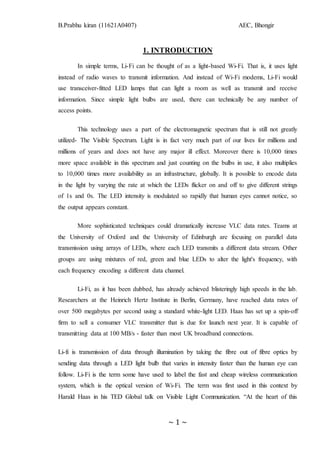
  • 3. B.Prabhu kiran (11621A0407) AEC, Bhongir ~ 3 ~ Fig. 1.1 Li-Fi Environment
  • 4. B.Prabhu kiran (11621A0407) AEC, Bhongir ~ 4 ~ 2. HISTORY OF LI-FI 2.1 The need for Visible Light Communication (VLC) Issues regarding Radio Waves: 1. Capacity:  Radio waves are limited, scar and expensive. We only have a certain range of it.  With the advent of the new generation technologies as of likes of 2.5G, 3G, 4G and so on we are running out of spectrum. 2. Efficiency:  There are 1.4 million cellular radio base stations. They consume massive amount of energy.  Most of this energy is not used for transmission but for cooling down the base stations.  Efficiency of such a base station is only 5% and that raise a very big problem. 3. Availability:  We have to switch off our mobiles in aero planes.  It is not advisable to use mobiles at places like petrochemical plants and petrol pumps.  Availability of radio waves causes another concern. 4. Security:  Radio waves penetrate through walls.  They can be intercepted. If someone has knowledge and bad intentions then he may misuse it. So we should look for other parts of EM waves. Gamma rays are simply very dangerous and thus can’t be used for our purpose of communication. X-rays are good in hospital and can’t be used either. Ultra-violet rays are sometimes good for our skin but for long duration it is dangerous. Infra-red rays are bad for our eyes and are therefore used at low power levels. We have already seen shortcomings of radio waves. So we are left with only Visible light spectrum.
  • 5. B.Prabhu kiran (11621A0407) AEC, Bhongir ~ 5 ~ Fig. 2.1 issues regarding Radio spectrum 2.2 Genesis of Li-Fi Harald Haas, a professor at the University of Edinburgh who began his research in the field in 2004, gave a debut demonstration of what he called a Li-Fi prototype at the TED Global conference in Edinburgh on 12th July 2011. He coined the term Li-Fi and is widely recognized as the original founder of Li-Fi. He is Chairman of Mobile Communications at the University of Edinburgh and co-founder of pureLiFi. Haas used a table lamp with an LED bulb to transmit a video of blooming flowers that was then projected onto a screen behind him. During the event he periodically blocked the light from lamp to prove that the lamp was indeed the source of incoming data. At TED Global, Haas demonstrated a data rate of transmission of around 10Mbps -- comparable to a fairly good UK broadband connection. Two months later he achieved 123Mbps. In 2011 German scientists succeeded in creating an800Mbps (Megabits per second) capable wireless network by using nothing more than normal red, blue, green and white LED light bulbs
  • 6. B.Prabhu kiran (11621A0407) AEC, Bhongir ~ 6 ~ (here), thus the idea has been around for awhile and various other global teams are also exploring the possibilities. VLC technology was exhibited in 2012 using Li-Fi. By August 2013, data rates of over 1.6 Gbit/s were demonstrated over a single color LED. In September 2013, a press release said that Li-Fi, or VLC systems in general, do not require line-of-sight conditions. One part of VLC is modeled after communication protocols established by the IEEE workgroup. However, the IEEE 802.15.7 standard is out-of-date. Specifically, the standard fails to consider the latest technological developments in the field of optical wireless communications, specifically with the introduction of optical orthogonal frequency-division multiplexing (O-OFDM) modulation methods which have been optimized for data rates, multiple-access and energy efficiency have. The introduction of O- OFDM means that a new drive for standardization of optical wireless communications is required. Nonetheless, the IEEE 802.15.7 standard defines the physical layer (PHY) and media access control (MAC) layer. The standard is able to deliver enough data rates to transmit audio, video and multimedia services. It takes into account the optical transmission mobility, its compatibility with artificial lighting present in infrastructures, the deviance which may be caused by interference generated by the ambient lighting. The MAC layer allows to use the link with the other layers like the TCP/IP protocol. The standard defines three PHY layers with different rates:  The PHY I was established for outdoor application and works from 11.67 Kbit/s to 267.6 Kbit/s.  The PHY II layer allows reaching data rates from 1.25 Mbit/s to 96 Mbit/s.  The PHY III is used for many emissions sources with a particular modulation method called colour shift keying (CSK). PHY III can deliver rates from 12 Mbit/s to 96 Mbit/s. The modulation formats recognized for PHY I and PHY II are the coding on-off keying (OOK) and variable pulse position modulation (VPPM). The Manchester coding used for the PHY I and PHY II layers include the clock inside the transmitted data by representing a logic 0 with an OOK symbol "01" and a logic 1 with an OOK symbol
  • 7. B.Prabhu kiran (11621A0407) AEC, Bhongir ~ 7 ~ "10", all with a DC component. The DC component avoids the light extinction in case of an extended line of logic 0. VLC technology is ready to use right now; it's being installed in museums and businesses across France, and is being embraced by EDF, one of the nation's largest utilities. Fig.2.2 Prof. Harald Hass
  • 8. B.Prabhu kiran (11621A0407) AEC, Bhongir ~ 8 ~ 3. WORKING PRINCIPLES Li-Fi is typically implemented using white LED light bulbs at the downlink transmitter. These devices are normally used for illumination only by applying a constant current. But unlike other light sources LEDs can turn on & off millions of times per second. However, by fast and subtle variations of the current, the optical output can be made to vary at extremely high speeds. This very property of optical current is used in Li-Fi setup. The operational procedure is very simple. If the LED is on, it transmits a digital 1, if it’s off it transmits a 0. The LEDs can be switched on and off very quickly, which gives nice opportunities for transmitting data. Hence all that is required is some LEDs and a controller that code data into those LEDs. All one has to do is to vary the rate at which the LED’s flicker depending upon the data we want to encode. Further enhancements can be made in this method, like using an array of LEDs for parallel data transmission, or using mixtures of red, green and blue LEDs to alter the light’s frequency with each frequency encoding a different data channel. Such advancements promise a theoretical speed of 10 Gbps – meaning one can download a full high-definition film in just 30 seconds. Fig.3.1 Block Diagram of LI-FI
  • 9. B.Prabhu kiran (11621A0407) AEC, Bhongir ~ 9 ~ To further get a grasp of Li-Fi consider an IR remote. It sends a single data stream of bits at the rate of 10,000-20,000 bps. Now replace the IR LED with a Light Box containing a large LED array. This system is capable of sending thousands of such streams at very fast rate. Light is inherently safe and can be used in places where radio frequency communication is often deemed problematic, such as in aircraft cabins or hospitals. So visible light communication not only has the potential to solve the problem of lack of spectrum space, but can also enable novel application. The visible light spectrum is unused; it's not regulated, and can be used for communication at very high speed. 3.1 Visible light communication (VLC): A potential solution to the global wireless spectrum shortage Li-fi (Light Fidelity) is a fast and cheap optical version of Wi-Fi, the technology of which is based on Visible Light Communication (VLC).VLC is a data communication medium, which uses visible light between 400 THz (780 nm) and 800 THz (375 nm) as optical carrier for data transmission and illumination. It uses fast pulses of light to transmit information wirelessly. The main components of this communication system are 1. A high brightness white LED, which acts as a communication source and 2. A silicon photodiode Which shows good response to visible wavelength region serving as the receiving element? LED can be switched on and off to generate digital strings of 1s and 0s. Data can be encoded in the light to generate a new data stream by varying the flickering rate of the LED. To be clearer, by modulating the LED light with the data signal, the LED illumination can be used as a communication source. Due to the physical properties of these components, information can only be encoded in the intensity of the emitted light, while the actual phase and amplitude of the light wave cannot be modulated. This significantly differentiates VLC from RF communications.VLC can only be realized as an IM/DD system, which means that the modulation signal has to be both real valued and unipolar. This limits the application of the well-researched and developed modulation schemes from the field of RF communications. Techniques such as on-off keying (OOK), pulse-position modulation (PPM), pulse-width
  • 10. B.Prabhu kiran (11621A0407) AEC, Bhongir ~ 10 ~ modulation (PWM) and unipolar M-ary pulse-amplitude modulation (M-PAM) can be applied in a relatively straightforward fashion. As the modulation speeds are increased, however, these particular modulation schemes begin to suffer from the undesired effects of intersymbol interference (ISI) due to the non-flat frequency response of the optical wireless communication channel. Hence, a more resilient technique such as OFDM is required. OFDM allows adaptive bit and energy loading of different frequency sub-bands according to the communication channel properties. This leads to optimal utilization of the available resources. OFDM achieves the throughput capacity in a non-flat communication channel even in the presence of nonlinear distortion. Such channel conditions are introduced by the transfer characteristic of an off-the-shelf LED that has a maximum 3 dB modulation bandwidth in the order of 20 MHz In fact, the record-breaking results have all been achieved using OFDM. Further benefits of this modulation scheme include simple equalization with single-tap equalizers in the frequency domain as well as the ability to avoid low-frequency distortion caused by flickering background radiation and the baseline wander effect in electrical circuits. Conventional OFDM signals are complex-valued and bipolar in nature. Therefore, the standard RF OFDM technique has to be modified in order to become suitable for IM/DD systems. A straightforward way to obtain a real-valued OFDM signal is to impose a Hermitian symmetry constraint on the sub-carriers in the frequency domain. However, the resulting time-domain signal is still bipolar. One way for obtaining a unipolar signal is to introduce a positive direct current (DC) bias around which the amplitude of the OFDM signal can vary as shown in Figure. (a) Unbiased bipolar OFDM signal (b) Biased unipolar OFDM signal Fig.3.2
  • 11. B.Prabhu kiran (11621A0407) AEC, Bhongir ~ 11 ~ The resulting unipolar modulation scheme is known as DC-biased optical OFDM (DCO-OFDM). The addition of the constant biasing level leads to a significant increase in electrical energy consumption. This can be easily visualized when Fig 3-2 (a) and Fig 3-2(b) are juxtaposed. However, if the light sources are used for illumination at the same time, the light output as a result of the DC bias is not wasted as it is used to fulfil the illumination function. Only if illumination is not required, such as in the uplink of a Li-Fi system, the DC bias can significantly compromise energy efficiency. Therefore, researchers have devoted significant efforts to designing an OFDM-based modulation scheme which is purely unipolar. Some well-known solutions include: asymmetrically clipped optical OFDM (ACO-OFDM), pulse-amplitude-modulated discrete multi-tone modulation (PAM-DMT), unipolar OFDM (U-OFDM), Flip-OFDM, spectrally-factorized optical OFDM (SFO- OFDM). The general disadvantage of all these techniques is a 50% loss in spectral efficiency, i.e., the data rates are halved. This limitation has recently been overcome by researchers at the University of Edinburgh. 3.1.1 Multiple accesses using VLC A networking solution cannot be realized without a suitable multiple access scheme that allows multiple users to share the communication resources without any mutual cross- talk. Multiple access schemes used in RF communications can be adapted for VLC as long as the necessary modifications related to the IM/DD nature of the modulation signals are performed. OFDM comes with a natural extension for multiple accesses – OFDMA. Single- carrier modulation schemes such as M-PAM, OOK and PWM require an additional multiple access technique such as frequency division multiple access (FDMA), time division multiple access (TDMA) and/or code division multiple access (CDMA). The results of an investigation regarding the performance of OFDMA versus TDMA and CDMA are presented in Fig 3-3. FDMA has not been considered due to its close similarity to OFDMA, and the fact that OWC does not use super heterodyning. In addition, due to the limited modulation bandwidth of the front-end elements, this scheme would not present a very efficient use of the LED modulation bandwidth.
  • 12. B.Prabhu kiran (11621A0407) AEC, Bhongir ~ 12 ~ Fig 3.3. TDMA vs. OFDMA vs. CDMA (with optical orthogonal code) in a six-user scenario) As shown in Fig. 3-3, CDMA is very inefficient as the use of unipolar signals creates significant interchannel interference (ICI) and a substantial increase in the power requirements compared to its application in RF communications. At the same time, the performance of TDMA barely surpasses that of OFDMA for the different scenarios. The higher power requirement of OFDMA compared to TDMA is caused by its wider time- domain signal distribution. This leads to the need for higher DC biasing levels and as a consequence to higher power consumption which is reflected in the shown signal-to-noise ratio (SNR). In a practical scenario where the functions of communication and illumination are combined, the difference in power consumption between the different schemes would diminish as the excess power due to the DC bias would be used for illumination purposes. It should be pointed out that this investigation has been performed for a flat linear additive white Gaussian noise (AWGN) channel where only clipping effects from below, applicable only to OFDMA, have been considered. This is due to the fact that nonlinear effects such as clipping from above as well as the nonlinear relationship between the modulating current signal and the emitted optical signal are device-specific, while clipping from below is inherent to any IM/DD system. Furthermore, low-frequency distortion effects from the DC- wander in electrical components as well as from the flickering of background light sources are also not considered. In a practical scenario, these effects would not be an issue for OFDMA, but are expected to decrease the performance of TDMA and CDMA. Therefore,
  • 13. B.Prabhu kiran (11621A0407) AEC, Bhongir ~ 13 ~ the design complexity of a TDMA or CDMA system increases as suitable techniques to deal with these problems need to be implemented. It is also worth noting that the non-flatness of the channel in a practical scenario would further degrade the performances of CDMA and TDMA compared to OFDMA. In VLC there exists an additional alternative dimension for achieving multiple accesses. This is colour, and the corresponding technique is wavelength division multiple access (WDMA). WDMA harnesses the different light wavelengths to facilitate multiple- user access. This scheme could reduce the complexity in terms of signal processing. However, it would lead to increased hardware complexity as well as to the need at each access point for multiple transmitter elements with narrow wavelength emission. This immediately puts strict requirements on the optical front-end elements, and compromises SNR and, hence, capacity. In addition, WDMA excludes the usage of a large variety of off- the-shelf LEDs as most of them are not optimized for WDMA. The typical emission profile of an off-the-shelf white LED is illustrated in Fig 3-4. At the same time, light sources with different narrow wavelength emission spectra have different modulation frequency profiles as well as different optical efficiencies. When combined with the varying responsively of photo detectors at different wavelengths, as shown in figure, these differences complicate immensely the fair distribution of communication resources between multiple users. (a) Typical spectrum of a white-phosphor LED (b) Typical responsively of photo detector. Fig.3.4
  • 14. B.Prabhu kiran (11621A0407) AEC, Bhongir ~ 14 ~ 3.2 Technologyin Brief LI-FI is a new class of high intensity light source of solid state design bringing clean lighting solutions to general and specialty lighting. It is a 5G visible light communication system that uses light from light-emitting diodes (LEDs) as a medium to deliver networked, mobile, high-speed communication in a similar manner as Wi-Fi. Visible light communications (VLC) works by switching bulbs on and off within nanoseconds, which is too quickly to be noticed by the human eye. Although Li-Fi bulbs would have to be kept on to transmit data, the bulbs could be dimmed to the point that they were not visible to humans and yet still functional. The light waves cannot penetrate walls which makes a much shorter range, though more secure from hacking, relative to Wi- Fi. Direct line of sight isn't necessary for Li-Fi to transmit signal and light reflected off of the walls can achieve 70 Mbit/s. A data rate of greater than 100 Mbps is possible by using high speed LEDs with appropriate multiplexing techniques. VLC data rate can be increased by parallel data transmission using LED arrays where each LED transmits a different data stream. There are reasons to prefer LED as the light source in VLC while a lot of other illumination devices like fluorescent lamp, incandescent bulb etc. are available. 3.2.1 Li-Fi Construction The LIFI™ product consists of 4 primary sub-assemblies: • Bulb • RF power amplifier circuit (PA) • Printed circuit board (PCB) • Enclosure Fig.3.5. Li-Fi bulb with PCB
  • 15. B.Prabhu kiran (11621A0407) AEC, Bhongir ~ 15 ~  The PCB controls the electrical inputs and outputs of the lamp and houses the microcontroller used to manage different lamp functions.  An RF (radio-frequency) signal is generated by the solid-state PA and is guided into an electric field about the bulb.  The high concentration of energy in the electric field vaporizes the contents of the bulb to a plasma state at the bulb’s centre; this controlled plasma generates an intense source of light. All of these subassemblies are contained in an aluminium enclosure.  Function of the bulb: The heart of LIFI™ is the bulb sub-assembly where a sealed bulb is embedded in a dielectric material. This design is more reliable than conventional light sources that insert degradable electrodes into the bulb. The dielectric material serves two purposes; first, as a waveguide for the RF energy transmitted by the PA and second, as an electric field concentrator that focuses energy in the bulb. The energy from the electric field rapidly heats the material in the bulb to a plasma state that emits light of high intensity and full spectrum. 3.2.2 Uplink Up until now, research has primarily focused on maximizing the transmission speeds over a single unidirectional link. However, for a complete Li-Fi communication system, full duplex communication is required, i.e., an uplink connection from the mobile terminals to the optical AP has to be provided. Existing duplex techniques used in RF such time division duplexing (TDD) and frequency division duplexing (FDD) could be considered, where the downlink and the uplink are separated by different time slots, or different frequency bands respectively. However, FDD is more difficult to realize due to the limited bandwidth of the front-end devices, and because super heterodyning is not used in IM/DD systems. TDD provides a viable option, but imposes precise timing and synchronization constraints which are needed for data decoding, anyway. However, plain TDD assumes that both the uplink and the downlink transmissions are performed over the same physical wavelength. This could often be impractical as visible light emitted by the user terminal may not be desirable. Therefore, the most suitable duplex technique in Li-Fi is wavelength division duplexing (WDD), where the two communication channels are established over different electromagnetic wavelengths. Using infrared (IR) transmission is one viable option for establishing an uplink communication channel. A first commercially-available full duplex
  • 16. B.Prabhu kiran (11621A0407) AEC, Bhongir ~ 16 ~ Li-Fi modem using IR light for the uplink channel has recently been announced by pureLiFi. There is also the option to use RF communication for the uplink. In this configuration, Li-Fi may be used to do the “heavy lifting” and off-load data traffic from the RF network, and thereby providing significant RF spectrum relief. This is particularly relevant since there is a traffic imbalance in favour of the downlink in current wireless communication systems. 3.2.3 Summary The design and construction of the LIFI™ light source enable efficiency, long stable life, full spectrum intensity and dimming that is digitally controlled and easy to use. With this features LI-FI lighting applications work better compared to conventional approaches. This technology brief describes the general construction of LI-FI lighting systems and the basic technology building blocks behind their function. 3.3 Working models Within a local Li-Fi cloud several database services are supported through a heterogeneous communication sys-tem. In an initial approach, the Li-Fi Consortium defined different types of technologies to provide secure, reliable and ultra-high-speed wireless communication interfaces. These technologies included Giga-Speed technologies, optical mobility technologies, and navigation, precision location and gesture recognition technologies. For Giga-Speed technologies, the Li-Fi Consortium defined Giga-Dock, Giga- Beam, Giga-Shower, Giga-Spot and Giga-MIMO models to address different user scenarios for wireless indoor and indoor-like data transfers. While Giga-Dock is a wireless docking solution including wireless charging for smartphones tablets or notebooks, with speeds up to 10 Gbps, the Giga-Beam model is a point-to-point data link for kiosk applications or portable-to-portable data exchanges. Thus a two-hour full HDTV movie (5 GB) can be transferred from one device to another within four seconds. Giga-Shower, Giga-Spot and Giga-MIMO are the other models for in-house communication. There a transmitter or receiver is mounted into the ceiling connected to, for example, a media server. On the other side are portable or fixed devices on a desk in an office, in an operating room, in a production hall or at an airport. Giga-Shower provides unidirectional data services via
  • 17. B.Prabhu kiran (11621A0407) AEC, Bhongir ~ 17 ~ several channels to multiple users with gigabit-class communication speed over several meters. This is like watching TV channels or listening to different radio stations where no uplink channel is needed. In case Giga-Shower is used to sell books, music or movies, the connected media server can be accessed via Wi-Fi to process payment via a mobile device. Giga-Spot and Giga-MIMO are optical wireless single- and multi-channel Hotspot solutions offering bidirectional gigabit-class communication in a room, hall or shopping mall for example. a.Giga-Dock b. Giga-Beam
  • 18. B.Prabhu kiran (11621A0407) AEC, Bhongir ~ 18 ~ C.Giga-shower d. Giga-MIMO Fig 3-6: Giga-Speed usage models (Images courtesy: TriLumina Corp.)
  • 19. B.Prabhu kiran (11621A0407) AEC, Bhongir ~ 19 ~ 4. COMPARISON BETWEEN LI-FI & WI-FI Li-Fi is a term of one used to describe visible light communication technology applied to high speed wireless communication. It acquired this name due to the similarity to Wi-Fi, only using light instead of radio. Wi-Fi is great for general wireless coverage within buildings, and Li-Fi is ideal for high density wireless data coverage in confined area and for relieving radio interference issues. Table 1: Comparison between Li-Fi and Wi-Fi S.No Parameters Wireless Technologies Light Fidelity Wireless Fidelity 1 Speed for data transfer Faster transfer speed (>1Gbps) Slower transfer speed (150Mbps) 2 Medium through which data transfer occurs Light is Used as carrier Radio Spectrum is Used as carrier 3 Spectrum range Visible light spectrum has 10,000 time broad spectrum in comparison to radio frequency Radio frequency spectrum range is much narrower than visible light spectrum. 4 Cost Cheaper than Wi-Fi because free band doesn’t need license and it uses light. Expensive in comparison to Li-Fi because it uses radio spectrum which requires license 5 Network topology Point to point Point to point 6 Operating frequency Hundreds of Tera Hz 2.4 GHz
  • 20. B.Prabhu kiran (11621A0407) AEC, Bhongir ~ 20 ~ The table also contains the current wireless technologies that can be used for transferring data between devices today (i.e. Wi-Fi, Bluetooth and IrDA). Only Wi-Fi currently offer very high data rates. The IEEE 802.11.n in most implementations provides up to 150Mbit/s (in theory the standard can go to600Mbit/s) although in practice you receive considerably less than this. Note that one out of three of these is an optical technology. Li-Fi technology is based on LEDs for the transfer of data. The transfer of the data can be with the help of all kinds of light, no matter the part of the spectrum that they belong. That is, the light can belong to the invisible, ultraviolet or the visible part of the spectrum. Also, the speed of the internet is incredibly high and movies, games, music etc. can be downloaded in just a few minutes with the help of this technology. Also, the technology removes limitations that have been put on the user by the Wi-Fi. You no more need to be in a region that is Wi-Fi enabled to have access to the internet. You can simply stand under any form of light and surf the internet as the connection is made in case of any light presence. There cannot be anything better than this technology. Table 2: Comparison between current and future wireless technology Technology Speed Data Density Wi-Fi – IEEE802.11n 150 Mbps * Bluetooth 3 Mbps * IrDA 4 Mbps *** Wireless (future) Wi-Gig 2 Gbps ** Giga-IR 1 Gbps *** Li-Fi >1Gbps ****
  • 21. B.Prabhu kiran (11621A0407) AEC, Bhongir ~ 21 ~ 4.1 How is it different? Li-Fi technology is based on LEDs for the transfer of data. The transfer of the data can be with the help of all kinds of light, no matter the part of the spectrum that they belong. That is, the light can belong to the invisible, ultraviolet or the visible part of the spectrum. Also, the speed of the internet is incredibly high and you can download movies, games, music etc in just a few minutes with the help of this technology. Also, the technology removes limitations that have been put on the user by the Wi-Fi. You no more need to be in a region that is Wi-Fi enabled to have access to the internet. You can simply stand under any form of light and surf the internet as the connection is made in case of any light presence. There cannot be anything better than this technology. Li-Fi is a term often used to describe high speed VLC in application scenarios where Wi-Fi might also be used. The term Li-Fi is similar to Wi-Fi with the exception that light rather than radio is used for transmission. Li-Fi might be considered as complementary to Wi-Fi. If a user device is placed within a Li-Fi hot spot (i.e. under a Li-Fi light bulb), it might be handed over from the Wi-Fi system to the Li-Fi system and there could be a boost in performance.
  • 22. B.Prabhu kiran (11621A0407) AEC, Bhongir ~ 22 ~ 5. APPLICATIONS AREAS OF LI-FI TECHNOLOGY 5.1 Air Ways Whenever we travel through airways we face the problem in communication media, because the whole airways communications are performed on the basis of radio waves. To overcome this drawback on radio waves, Li-Fi is introduced. Fig 5-1 Use of Li-Fi in Aeroplane 5.2 Medical applications For a long time, medical technology has lagged behind the rest of the wireless world. Operating rooms do not allow Wi-Fi over radiation concerns, and there is also that whole lack of dedicated spectrum. While Wi-Fi is in place in many hospitals, interference from cell phones and computers can block signals from monitoring equipment. Li-Fi solves both problems: lights are not only allowed in operating rooms, but tend to be the most glaring (pun intended) fixtures in the room. And, as Haas mentions in his TED Talk, Li-Fi has 10,000 times the spectrum of Wi-Fi, so maybe we can delegate red light to priority medical data. Code Red!
  • 23. B.Prabhu kiran (11621A0407) AEC, Bhongir ~ 23 ~ Fig.5.2 Use of LI-FI in Medical Field 5.3 In traffic lights In traffic signals and brake lights Li-Fi can be used which will communicate with the cars and other vehicles and accidents can be decreased. Fig 5.3 Use of Li-Fi in traffic lights
  • 24. B.Prabhu kiran (11621A0407) AEC, Bhongir ~ 24 ~ 5.4Secure communication It is very useful to use VLC where a secure and private communication is necessary. In visual light communication, the node or any terminal attach to our network is visible to the host of network. Blocking the light and also blocks the signal. However, this is also a potential advantage from a security point of view. Light cannot penetrate walls as radio signals can, so drive-by hacking of wireless internet signals would be far more difficult, though not impossible. 5.5 Multi user communications Li-Fi supports the broadcasting of network. It helps to share multiple things at a single instance called broadcasting. 5.6 Lightings points used as Hotspot Any lightings device can be performed as a hotspot. It means that the light device like car lights, ceiling lights, street lamps etc. all are able to spread internet connectivity using visual light communication which helps us to use low cost architecture for hotspot. Hotspot is a limited region (usually public places) where a number of devices can access the internet connectivity. Fig 5.4 Every light emitting device acting as a Li-Fi Hotspot
  • 25. B.Prabhu kiran (11621A0407) AEC, Bhongir ~ 25 ~ 5.7 Smarter power plants Wi-Fi and many other radiation types are bad for sensitive areas. Like those surrounding power plants. But power plants need fast, inter-connected data systems to monitor things like demand, grid integrity and (in nuclear plants) core temperature. The savings from proper monitoring at a single power plant can add up to hundreds of thousands of dollars. Li-Fi could offer safe, abundant connectivity for all areas of these sensitive locations. Not only would this save money related to currently implemented solutions, but the draw on a power plant’s own reserves could be lessened if they haven’t yet converted to LED lighting. Fig.5.5 Use of LI-FI in Smart Power Plant 5.8 Undersea awesomeness Remotely operated underwater vehicles (ROVs) work great, except when the tether isn’t long enough to explore an area, or when it gets stuck on something. If their wires were cut and replaced with light, say from a submerged, high-powered lamp, then they would be much freer to explore. They could also use their headlamps to communicate with each other, processing data autonomously and referring findings periodically back to the surface, all the while obtaining their next batch of orders.
  • 26. B.Prabhu kiran (11621A0407) AEC, Bhongir ~ 26 ~ Fig.5.6 Use of VLC under water 5.9 It could keep people informed and save lives If there’s an earthquake or a hurricane in a city, the average people may not know what the protocols are for those kinds of disasters. Until they pass under a street light, that is. With Li-Fi, if there’s light, they’re online. Subway stations and tunnels, common dead zones for most emergency communications, pose no obstruction. Plus, in times less stressing cities could opt to provide cheap high-speed Web access to every street corner.
  • 27. B.Prabhu kiran (11621A0407) AEC, Bhongir ~ 27 ~ 6. ADVANTAGES OVER RADIO WAVES The Li-Fi has the following advantages over RF based technologies. 1. Faster Data Transfer: Li-Fi is much faster than Wi-Fi and other current technologies based on radio spectrum. 2. Free from Frequency Bandwidth Problem: Li-Fi is a communication media in the form of light, so no matter about the frequency bandwidth problem. It does not require the any bandwidth spectrum i.e. we don’t need to pay any amount for communication and license. 3. Unlimited capacity: Visible light is part of the electromagnetic spectrum and 10,000 times bigger than the radio spectrum, affording potentially unlimited capacity. 4. Availability: Light Source is available everywhere, so possibilities of this technology are very high. Data can be accessed in home, streets, hospitals, hotels etc. 5. Efficiency: Li-Fi uses LED lamps which are very energy efficient. This saves a lot of electricity. If all the light bulbs are exchanged with LEDs, one billion barrels of oil could be saved every year, which again translates into energy production of 250 nuclear power plants. 6. High Security: Data can be accessed only if light is available. Light cannot penetrate through walls. So there is less chance of unauthorized access of data, though it is not impossible. 7. Harmless: Li-Fi is a green information technology unlike radio waves and other communication waves affects on the birds, human bodies etc. It never gives such side effects on any living thing
  • 28. B.Prabhu kiran (11621A0407) AEC, Bhongir ~ 28 ~ . 6.1(a) 6.1( b) Fig.6.1 (a&b) Electromagnetic Spectrum
  • 29. B.Prabhu kiran (11621A0407) AEC, Bhongir ~ 29 ~ 7. CHALLENGES OF LI-FI Apart from many advantages over Wi-Fi, Li-Fi technology is facing some challenges. They are: 1. Presence of Light: Presence of light is essential. One can’t access internet if there is no light source. Even on daytime the lights must be kept on to access data through Li-Fi. 2. Line of Sight: Li-Fi requires direct line of sight. Indoors, one would not be able to shift the receiving device. This is because visible light can’t penetrate through brick walls or objects as radio waves and is easily blocked by somebody simply walking in front of LED source. 3. Low efficiency with bulbs: It has higher efficiency with LEDs but very low efficiency with bulbs. So, one has to use expensive LEDs to get a decent data transmission rate. 4. Interference with other light sources: Other light sources can easily interfere with Li-Fi thus interrupting data transmission. When set up outdoors, the apparatus would need to deal with ever changing conditions. Also the power cord immediately becomes data stream. 5. Not ready for two way communication: Li-Fi works well for one way communication, i.e., the devices can receive data through it. But in case of two way communication, there is no such well defined and reliable way how the device will transmit data back.
  • 30. B.Prabhu kiran (11621A0407) AEC, Bhongir ~ 30 ~ 8. CONCLUSION The possibilities are numerous and can be explored further. If his technology can be put into practical use, every bulb can be used something like a Wi-Fi hotspot to transmit wireless data and we will proceed toward the cleaner, greener, safer and brighter future. The concept of Li-Fi is currently attracting a great deal of interest, not least because it may offer a genuine and very efficient alternative to radio-based wireless. As a growing number of people and their many devices access wireless internet, the airwaves are becoming increasingly clogged, making it more and more difficult to get a reliable, high-speed signal. This may solve issues such as the shortage of radio-frequency bandwidth and also allow internet where traditional radio based wireless isn’t allowed such as aircraft or hospitals. One of the biggest attractions of VLC is the energy saving of LED technology. Nineteen per cent of the worldwide electricity is used for lighting. Thirty billion light bulbs are in use worldwide. Assuming that all the light bulbs are exchanged with LEDs, one billion barrels of oil could be saved every year, which again translates into energy production of 250 nuclear power plants. There are few shortcomings in this technology right now, but those can be overcome in near future.
  • 31. B.Prabhu kiran (11621A0407) AEC, Bhongir ~ 31 ~ 9. REFRENCES 1. International Journal of advances in computing & communications, vol 1, 2013 http://www.ijacc.org 2. http://en.wikipedia.org/wiki/Li-Fi 3. http://oledcomm.com/lifi.html 4. http://en.wikipedia.org/wiki/visible_light_communication