Substation Neutral Earthing

Substation Neutral Earthing Substation Neutral EarthingSubstation Neutral EarthingSubstation Neutral EarthingSubstation Neutral EarthingSubstation Neutral EarthingSubstation Neutral EarthingSubstation Neutral EarthingSubstation Neutral EarthingSubstation Neutral EarthingSubstation Neutral EarthingSubstation Neutral EarthingSubstation Neutral EarthingSubstation Neutral EarthingSubstation Neutral EarthingSubstation Neutral EarthingSubstation Neutral EarthingSubstation Neutral EarthingSubstation Neutral EarthingSubstation Neutral EarthingSubstation Neutral EarthingSubstation Neutral EarthingSubstation Neutral EarthingSubstation Neutral EarthingSubstation Neutral EarthingSubstation Neutral EarthingSubstation Neutral EarthingSubstation Neutral EarthingSubstation Neutral EarthingSubstation Neutral EarthingSubstation Neutral EarthingSubstation Neutral EarthingSubstation Neutral EarthingSubstation Neutral EarthingSubstation Neutral EarthingSubstation Neutral EarthingSubstation Neutral EarthingSubstation Neutral EarthingSubstation Neutral EarthingSubstation Neutral EarthingSubstation Neutral EarthingSubstation Neutral EarthingSubstation Neutral EarthingSubstation Neutral Earthing

Empfohlen
Weitere ähnliche Inhalte
Was ist angesagt?
Was ist angesagt? (20)
Ähnlich wie Substation Neutral Earthing
Ähnlich wie Substation Neutral Earthing (20)
Mehr von Power System Operation
Mehr von Power System Operation (20)
Kürzlich hochgeladen
Kürzlich hochgeladen (20)
Substation Neutral Earthing
- 2. Distribution systems are earthed to create a reference point for the system voltage, to facilitate the detection and discriminative isolation of faults involving contact to earth, and to limit over-voltages under transient conditions. A neutral earthing system is a system in which the neutral is connected to earth, either solidly, or through a resistance or reactance of value sufficient to materially reduce transients, and to give sufficient current for selective earth fault protection devices to operate. Sensitive fault detectors allow the reduction of fault currents to very low values.
- 3. Unearthed neutrals were used in the past due to the fact that the first earth fault did not require tripping of the system. An unscheduled shutdown on the first earth fault was particularly undesirable for industries that were based on continuous processes and where continuation of the supply even under single fault conditions was necessary. Although achieving the initial goal, the unearthed system provided no control of transient over-voltages.
- 4. Neutral earthing systems are similar to fuses in that they do nothing until something in the system goes wrong. Then, like fuses, they protect personnel and equipment from damage. Damage comes from two factors, how long the fault lasts and how large the fault current is. Earth fault relays trip breakers and limit how long a fault lasts and neutral earthing resistors limit how large the fault current is. There are Five Methods of Neutral Earthing: •Unearthed neutral system •Solid neutral earthed system •Resistance neutral earthing system o Low resistance earthing o High resistance earthing •Resonant neutral earthing system •Transformer earthing system
- 5. Unearthed Systems In a unearthed neutral system there is no internal connection between the conductors and earth. However capacative coupling exists between the system conductors and the adjacent earthed surfaces. Consequently, the “unearthed system” is, in reality, a “capacative earthed system” by virtue of the distributed capacitance. As a result, this series resonant L-C circuit can create over-voltages well in excess of line-to-line voltage when subjected to repetitive re-strikes of one phase to earth. This in turn, reduces insulation life resulting in possible equipment failure (Fig.1).
- 6. Under normal operating conditions, this distributed capacitance causes no problems. In fact, it is beneficial because it establishes, in effect, a neutral point for the system. As a result, the phase conductors are stressed at only line-to- neutral voltage above earth potential. But problems can rise in earth fault conditions. A earth fault on one line results in full line-to-line voltage appearing throughout the system, between the conductors and earthed surfaces. Thus, a voltage 1,73 times the normal voltage is present on all insulation in the system. This situation can often cause failures in transformers, due to insulation breakdown.
- 7. Solidly Earthed Systems In a solidly earthed system, the neutral point is connected directly to earth, either directly or via a virtual neutral transformer. Generally all LV systems are solidly earthed. For MV and HV systems, solid earthing is the cheapest method but has a number of serious drawbacks. •High fault currents with resultant damage to plant •High current will cause tripping of all phases Neutral earthing resistors are used to limit the fault current in transformers When a phase to earth occurs, the fault current is limited only by the soil resistance. This current, which can be very high, can damage the windings. Low voltage networks are generally solidly earthed and resistive neutral earthing is generally only applied to MV and HV lines.
- 8. Resistive Earthed Systems The main reasons for limiting the phase to earth current by resistance earthing are: •To reduce burning and melting effects in faulted electrical equipment such as switchgear, transformers, cables. •To reduce mechanical stresses in circuits/equipment carrying fault currents. •To reduce electrical-shock hazards to personnel caused by stray earth fault. •To reduce the arc blast or flash hazard. •To reduce the momentary line-voltage dip. •To secure control of the transient over-voltages while at the same time. •To improve the detection of the earth fault in a power system. Fig. 2: A solidly earthed system [4].
- 9. Earthing resistors are generally connected between earth and the neutral of substation transformers, (Fig. 3), to limit maximum fault current to a value which will not damage equipment, while allowing sufficient fault current to operate earth fault protective relays. Although it is possible to limit fault currents with high resistance neutral earthing resistors, earth short circuit currents may be extremely reduced and protection devices may not sense the fault. Fig. 3: Resistive neutral earthing [4]. It is common to limit single phase fault currents with low resistance neutral earthing resistors to approximately the rated current of the transformer. In addition, limiting fault currents to predetermined maximum values permits selective coordination of protective devices, which minimises system disruption and allows for quick location of faults.
- 10. Earthing resistance can be classified into high and low value types. The resistance is also categorised on the basis of time they can withstand the fault current. Typical durations are 1 s, 10 s, 1 min and 10 min rating. The extended time rating resistor is used in systems where the reliability of the system is critical. In these situations, a high resistance which can sustain the fault for a long period is used. When an earth fault occurs of one phase, an alarm is generated. However, the system continues to run until the next scheduled shutdown. Earth fault current flowing through either type of resistor when a single phase faults to earth will increase the phase-to-earth voltage of the remaining two phases. As a result, conductor insulation and surge arrestor ratings must be based on line-to-line voltage. This temporary increase in phase-to-earth voltage should also be considered when selecting two and three pole breakers installed on resistance earthed low voltage systems
- 11. High Resistance Neutral Earthing Systems High resistance earthing systems are designed for limiting phase-to-earth fault currents in distribution systems by using a neutral earthed resistor between the transformer or generator neutral and earth. With this type of system earthing there is no need to trip the corresponding circuit breaker in the case of a phase- to-earth fault. The system will only provide an alarm while the faulted feeder remains operational until the fault is located and cleared. This functionality is required in certain electrical applications where the risks associated to interrupting the electrical service are higher than the risk of letting the system run with a phase-to-earth fault limited by the resistor. Fig. 4: Delta star transformer earthing [4].
- 12. Besides preventing the feeder from tripping by limiting the fault current, some of the advantages of a High Resistance earthing system include: •Transient overvoltages are reduced •Arc flash risks are diminished •Fault location is easily accomplished The disadvantage is that, in case of single earth fault, the voltage at the two other healthy phases tends to reach the value of the line-to-line voltage, depending on the relation between zero and direct sequence impedance seen from the fault. This rise in phase voltage increases the probability of a second earth fault in a different phase and a different feeder. In this case, a phase-to-earth-to-phase fault current will flow with a magnitude limited by: •The total impedance of the earth path •The possible occurrence of an arc flash
- 13. The neutral earthing resistor cannot limit the magnitude of this fault because the resistor is outside of its trajectory. The fault will evolve until being finally cut off by the overcurrent protection of the feeders involved, and the risks associated to a sudden interruption will not be avoided. Second Earth Fault Protection Systems have been developed to prevent this situation by tripping only one of the feeders, the one with the lowest priority, in the event of a second phase-to- earth fault, leaving the rest of the system operational with only a phase-to-earth fault limited in magnitude by the neutral earthing resistor. Coordination with circuit breakers’ overcurrent protection and priority settings are important considerations. If the second phase-to-earth fault in a different phase occurs in the same feeder that had the initial fault the second earth fault protection system will not operate, leaving the responsibility for tripping or disconnecting the feeder to the circuit breaker’s overcurrent protection or fuses.
- 14. Fig. 5: Zig-zag transformer neutral earthing [4]. Low Resistance Neutral Earthing Systems Low resistance earthing is used in large MV/HV electrical networks where there is a high level of capital equipment and network interruptions have a significant economic impact. These NERs are generally sized to limit the fault current to a level enough to operate protective devices yet not enough to create major damage at the fault point.
- 15. Earthing via a Transformer or Neutral Electromagnetic Coupler (NEC) Where the neutral point is not available, an artificial earth can be created by using a transformer. The earthing transformer is used to provide a path to an unearthed system or when the system neutral is not available for some reason, for example, when a system is delta connected. It provides a low impedance path to the neutral and also limits the transient overvoltage when the earth faults occur in the system. The earthing of the system can be done in the following way: Delta-Star Earthing Transformer In a case of delta-star earthing transformer, the delta side is closed to provide a path for zero-sequence current. The star winding must be of the same voltage rating as the circuit that is to be earthed, whereas the delta voltage rating can be chosen to be any standard voltage level.
- 16. Fig. 6: The Petersen coil system [4]. Zig-zag Transformer A zig-zag transformer can be used for providing earthing on the transformer. It provides insulation between the earth and the component so that the system component may not be affected by the fault currents. The zig-zag transformer cancels out the harmonics of the power system. It also protects the power system by reducing the stress of the voltage under a fault condition. The zig-zag transformer has no secondary winding. It is a three-limbed (branched) transformer where each limb has two identical windings. One set of windings is connected in the star to provide the neutral point.
- 17. Resonant Earthed Neutral Fault currents can also be reduced by earthing the neutral through an inductive impedance. Adding inductive reactance from the system neutral point to earth is an easy method of limiting the available earth fault from something near the maximum 3-phase short circuit capacity to a relatively low value. To limit the reactive part of the earth fault current in a power system a neutral point reactor can be connected between the transformer neutral and the station earthing system. Fig. 7: Plunger type NERC (Trench).
- 18. Petersen Coil Earthing A Peterson coil is an adjustable iron cored reactor used to neutralise the capacitive earth fault current in a power system. When a phase-to-earth fault occurs in unearthed 3-phase systems, the phase voltage of the faulty phase is reduced to the earth potential as the capacitance of the faulty line is discharged at the fault location, the phase-to-earth voltage of the other two phases rises by √3 times. A charging current occurs between these phase-to-earth capacitances, which will continue to flow via the fault path while it remains. A modern steplessly adjustable Petersen coil consists of an iron-cored reactor connected between the star point of the substation transformer and earth in a three-phase system. In the event of a fault, the capacative earth fault current (Ir +Iy) is now neutralised by the current in the reactor (Ir) as this is equal in magnitude, but 180° out-of-phase. Petersen coils adjust automatically to compensate for the earth fault current. Fig. 7 shows a plunger type adjustable Petersen coil. The value of the inductance in the Petersen coil needs to match the value of the network capacitance which may vary, as and when switching in the network is carried out. Modern coil controllers continually monitor the zero-sequence voltage and detect any change which occurs. When there is a change in the network capacitance, the controller auto-tunes the Petersen coil to this new level to ensure that it is tuned to the correct point to immediately neutralise any earth fault which may occur. This rapid earth fault current limiting occurs automatically without any further intervention from the system [2].
- 19. The Petersen coil may also be referred to as an arc suppression coil (ASC). Technology and Design Liquid neutral earthing resistors (LNER) The design of a liquid neutral earthing resistor is a large tank containing an electrolyte solution (distilled water with a small amount of electrolytic powder).(Fig.8) The outer case of the tank is connected solidly to the earth point. An inner electrode which is insulated from the tank, provides the connection to the transformer neutral point. At commissioning, small amounts of electrolyte are added to the water to increase the conductivity of the solution until it reaches the calibrated resistance level. The final result is a high current carrying capacity fluid with a high resistance, in a very robust and low maintenance package.
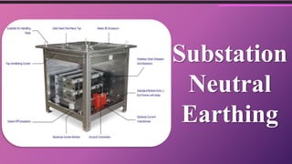
- 20. The LNER has a fixed structure as opposed to the more familiar liquid starter resistors or rheostats, and is therefore simpler to construct and calibrate. The amount of liquid in the tank provides a high heat absorption capacity. Problems with LNERs include a wide tolerance on ohmic values , and the necessity to recalibrate at regular intervals. Fig. 9: Solid earthing resistor (Postglover). Solid Earthing Resistors Solid neutral earthing resistors consist of coils of resistive material wound on insulators. The resistor uses unforced air cooling, and carful design is required to ensure that temperature limits are not exceeded. Resistive material is usually stainless steel or some other alloy. The solid earthing resistor may include a current transformer to drive a protection device. The current transformer is required to withstand the fault current. However in the case of resistive earthing, the fault current is greatly reduced and the design of the CT is not so severe.