
Empfohlen
Empfohlen
Weitere ähnliche Inhalte
Was ist angesagt?
Was ist angesagt? (16)
Ähnlich wie Kappa pump and motor units high pressure hydraulic gear units catalog
Ähnlich wie Kappa pump and motor units high pressure hydraulic gear units catalog (18)
Kürzlich hochgeladen
Kürzlich hochgeladen (20)
Kappa pump and motor units high pressure hydraulic gear units catalog
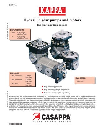
- 1. Edition:03/03.2006Replaces:K02TA K 03 T A KAPPA pump and motor units consist essentially of a housing and a mounting flange in cast iron of superior mechanical specifications. KAPPA is available with mountig flanges and side or rear ports according to SAE and European standard. The rigidity of assembly and the compact design of KAPPA pumps and motors ensure reliability and high volumetric effi- ciency also at high operating pressures. Infinite care and attention is taken over the design and construction of each single component, and with quality monitored unceasingly, the result is a consistent, perfectly balanced assembly that guarantees unbroken service under the most arduous operating conditions. KAPPA series is the right choice wherever noise, contami- nation, non inflammable fluids and size are critical factors. The wide choice of combinations of mounting flanges, shafts and ports ensure to KAPPA series to be applied in a vast range of application. PRESSURE Max. Continuous 4133 psi (285 bar) Max. Intermittent 4350 psi (300 bar) Max. Peak 4785 psi (330 bar) MAX. SPEED 4000 min-1 DISPLACEMENTS From 0.30 in3 /rev (4,95 cm3 /rev) To 4.50 in3 /rev (73,82 cm3 /rev) Hydraulic gear pumps and motors two piece cast iron housing l High operating pressures l High efficiency at high temperature l Exceptional working life expectancy *D0004430*
- 2. 003 D006-002 Kappa Section Description Page FEATURES . . . . . . . . . . . . . . . . . . . . . . . . . . . . . . . . . . . . . . . . . . . . . . . 1 GENERAL DATA PUMPS . . . . . . . . . . . . . . . . . . . 3 KP 20 PERFORMANCE CURVES . . . . . . . . . . . . . . . 6 KP 30 PERFORMANCE CURVES . . . . . . . . . . . . . . . 9 SINGLE GEAR PUMPS KP 20 EUROPEAN STANDARD . . . . . . . . . . . . . . . . 12 KP 20 SAE STANDARD . . . . . . . . . . . . . . . . . . . . 15 KP 30 EUROPEAN STANDARD . . . . . . . . . . . . . . . . 23 KP 30 SAE STANDARD . . . . . . . . . . . . . . . . . . . . 31 GENERALITY . . . . . . . . . . . . . . . . . . . . . . . . . . 35 MULTIPLE GEAR PUMPS KP 20 EUROPEAN STANDARD . . . . . . . . . . . . . . . . 40 KP 20 SAE STANDARD . . . . . . . . . . . . . . . . . . . . 46 KP 30 EUROPEAN STANDARD . . . . . . . . . . . . . . . . 56 PORTS CONNECTORS TIGHTENING TORQUE . . . . . . . . . . . . . . . . . . . . . . . . . . . . . . . . . . . . . . . . . 74 GENERAL DATA MOTORS . . . . . . . . . . . . . . . . . . 75 KM 20 PERFORMANCE CURVES . . . . . . . . . . . . . . . 78 KM 30 PERFORMANCE CURVES . . . . . . . . . . . . . . . 81 GEAR MOTORS KM 20 EUROPEAN STANDARD . . . . . . . . . . . . . . . . 84 KM 20 SAE STANDARD . . . . . . . . . . . . . . . . . . . . 87 KM 30 EUROPEAN STANDARD . . . . . . . . . . . . . . . . 95 KM 30 SAE STANDARD . . . . . . . . . . . . . . . . . . . . 103 KM 30 ISO STANDARD. . . . . . . . . . . . . . . . . . . . . 106 INSTRUCTIONS . . . . . . . . . . . . . . . . . . . . . . . . . . . . . . . . . . . . . . . . . . . . . 108 INDEX 02/06.05 Modification from former edition.
- 3. Kappa D006-003 003 1 ›03/03.2006Replaces:02/06.05 FEATURES GENERAL NOTES Available with different inlet and outlet ports. If you use fire resistant fluids specify the type of them at the order. For more information please consult our technical sales department. Construction External gear type pumps and motors Mounting EUROPEAN - SAE - ISO standard flanges Line connections Screw and flange Direction of rotation (looking on drive shaft) Anti-clock (S) - clockwise (D) - reversible (L, R or B) Inlet pressure range for pumps 10 ¸ 44 psi - [0,7 ¸ 3 bar (abs.)] Max back pressure for single rotation motors p1 (continuous) max 73 psi (5 bar) p2 (for 20 s) max 116 psi (8 bar) p3 (for 8 s) max 218 psi (15 bar) Max drain line pressure on the reversible rotation motors 73 psi (5 bar) Max back pressure on the series motors 2175 psi (150 bar) Fluid temperature range See table (1) Fluid Mineral oil based hydraulic fluids to ISO/DIN and fire resistant fluids [see table (1)]. For other fluids please consult our technical sales department. Viscosity range From 60 to 456 SSU [12 to 100 mm2 /s (cSt)] recommended Filtering requirement See table (2) Tab. 1 Type Fluid composition Max pressure psi - (bar) Max speed min-1 Temperature °F - (°C) Seals (u)Min Max continuous Max peak ISO/DIN Mineral oil based hydraulic fluid to ISO/DIN See page 3, 4 75,76 See page 3, 4 75,76 -13 (-25) 176 (80) 212 (100) N N-H -13 (-25) 230 (110) 257 (125) V HFA Oil emulsion in water 5 ¸ 15% of oil 725 (50) 1500 36 (2) 131 (55) N HFB Water emulsion in oil 40 % of water 1740 (120) 1500 36 (2) 140 (60) N HFC Water - glycol 1450 (100) 1500 -4 (-20) 140 (60) N Bz HFD Phosphate ester 2175 (150) 1500 14 (-10) 176 (80) V Bz (u) N= Buna N (standard) - N-H= Buna N and high back pressure shaft seals - V= Viton N Bz= Buna N and Bronze thrust plates - V Bz= Viton and Bronze thrust plates Casappa recommends to use its own production filters: Tab. 2 Working presure psi (bar) Dp<2030 (140) 2030<Dp<3045 (140) (210) Dp>3045 (210) Contamination class NAS 1638 10 9 8 Contamination class ISO 4406 21/19/16 20/18/15 19/17/14 Achieved with filter ßx(c) ³75 25 mm 10 mm 10 mm
- 4. Kappa 2 003 D006-003 01/03.02 PRESSURE DEFINITION p1 Max. continuous pressure p2 Max. intermittent pressure p3 Max. peak pressure Clockwise rotation Reversible rotationAnti-clock rotation DEFINITION OF ROTATION DIRECTION LOOKING ON THE DRIVE SHAFT
- 5. Kappa D006-004 003 3 Pump type Displacement Max. pressure Max. speed Min. speed p1 p2 p3 in3 /rev (cm3 /rev) psi (bar) min -1 KP 20•4 0.30 (4,95) 4133 (285) 4350 (300) 4785 (330) 4000 350 KP 20•6,3 0.40 (6,61) 4133 (285) 4350 (300) 4785 (330) 4000 350 KP 20•8 0.50 (8,26) 4133 (285) 4350 (300) 4785 (330) 3500 350 KP 20•11,2 0.69 (11,23) 3988 (275) 4205 (290) 4640 (320) 3500 350 KP 20•14 0.89 (14,53) 3843 (265) 4205 (290) 4640 (320) 3500 350 KP 20•16 1.03 (16,85) 3770 (260) 4205 (290) 4640 (320) 3000 300 KP 20•20 1.29 (21,14) 3045 (210) 3335 (230) 3625 (250) 3000 300 KP 20•25 1.61 (26,42) 2610 (180) 2900 (200) 3190 (220) 2500 300 KP 20•31,5 2.01 (33,03) 2030 (140) 2320 (160) 2610 (180) 2000 300 KAPPA 20 GENERAL DATA PUMPS p3= Max. peak pressurep1= Max. continuous pressure p2= Max. intermittent pressure KP 20 01/03.02 The values in the table refer to unidirectional pumps. Reversible pump max pressures are 15% lower than those shown in table. For different working conditions please consult our sales department.
- 6. Kappa 4 003 D006-004 KAPPA 30 GENERAL DATA PUMPS KP 30 p3= Max. peak pressurep1= Max. continuous pressure p2= Max. intermittent pressure The values in the table refer to unidirectional pumps. Reversible pump max pressures are 15% lower than those shown in table. For different working conditions please consult our sales department. 01/03.02 Pump type Displacement Max. pressure Max. speed Min. speed p1 p2 p3 in3 /rev (cm3 /rev) psi (bar) min -1 KP 30•27 1.63 (26,7) 4060 (280) 4350 (300) 4495 (310) 3000 350 KP 30•34 2.11 (34,56) 3770 (260) 4060 (280) 4350 (300) 3000 350 KP 30•38 2.40 (39,27) 3770 (260) 4060 (280) 4350 (300) 3000 350 KP 30•43 2.68 (43,98) 3625 (250) 3915 (270) 4205 (290) 3000 350 KP 30•51 3.16 (51,83) 3335 (230) 3625 (250) 3915 (270) 2500 350 KP 30•56 3.45 (56,54) 3118 (215) 3408 (235) 3698 (255) 2500 350 KP 30•61 3.74 (61,26) 2900 (200) 3190 (220) 3480 (240) 2500 350 KP 30•73 4.50 (73,82) 2610 (180) 2900 (200) 3190 (220) 2500 350
- 7. Kappa D006-004 003 5 DESIGN CALCULATIONS FOR PUMPS 02/06.05 Q = V(cm3 /rev) • hv • n • 10-3 [l/min] M = Dp (bar) • V (cm3 /rev) [Nm] 62,83 • hm P = Dp (bar) • V (cm3 /rev) • n [kW] 600 • 1000• ht Note: Diagrams providing approximate selection data will be found on subsequent pages. Q US gpm (l/min) Delivery M lbf in (Nm) Torque P HP (kW) Power V in3 /rev (cm3 /rev) Displacement n min -1 Speed Dp psi (bar) Pressure hv= hv (V,Dp, n) (» 0,98) Volumetric efficiency hm= hm (V,Dp, n) (» 0,90) Mechanical efficiency ht = hv • hm (» 0,88) Overall efficiency
- 8. Kappa 20 6 003 D006-005 KAPPA 20 GEAR PUMPS PERFORMANCE CURVES KP 20 Each curve has been obtained at 122 °F (50 °C), using oil with viscosity 168 SSU (36 cSt) at 104 °F (40 °C) and at these pressures. KP 20•4 . . . . . . 290-4133 psi (20-285 bar) KP 20•6,3 . . . . 290-4133 psi (20-285 bar) KP 20•8 . . . . . . 290-4133 psi (20-285 bar) KP 20•11,2 . . . 290-3988 psi (20-275 bar) KP 20•14 . . . . . 290-3843 psi (20-265 bar) KP 20•16 . . . . . 290-3770 psi (20-260 bar) KP 20•20 . . . . . 290-3045 psi (20-210 bar) KP 20•25 . . . . . 290-2610 psi (20-180 bar) KP 20•31,5 . . . 290-2030 psi (20-140 bar) KP 20 KP 20•6,3KP 20•4 01/03.02
- 9. Kappa 20 D006-005 003 7 KP 20•8 KP 20•11,2 KP 20•14 KP 20•16 KAPPA 20 GEAR PUMPS PERFORMANCE CURVES KP 20 01/03.02
- 10. Kappa 20 8 003 D006-005 KP 20•20 KAPPA 20 GEAR PUMPS PERFORMANCE CURVES KP 20 KP 20•31,5 KP 20•25 01/03.02
- 11. Kappa 30 D006-006 003 9 KAPPA 30 GEAR PUMPS PERFORMANCE CURVES KP 30 Each curve has been obtained at 122 °F (50°C), using oil with viscosity 168 SSU (36 cSt) at 104 °F (40°C) and at these pressures. KP 30•27 . . . . . 290-4060 psi (20-280 bar) KP 30•34 . . . . . 290-3770 psi (20-260 bar) KP 30•38 . . . . . 290-3770 psi (20-260 bar) KP 30•43 . . . . . 290-3625 psi (20-250 bar) KP 30•51 . . . . . 290-3335 psi (20-230 bar) KP 30•56 . . . . . 290-3118 psi (20-215 bar) KP 30•61 . . . . . 290-2900 psi (20-200 bar) KP 30•73 . . . . . 290-2610 psi (20-180 bar) KP 30•27 KP 30•34 KP 30 01/03.02
- 12. Kappa 30 10 003 D006-006 KP 30•38 KP 30•43 KP 30•51 KP 30•56 KAPPA 30 GEAR PUMPS PERFORMANCE CURVES KP 30 01/03.02
- 13. Kappa 30 D006-006 003 11 KP 30•73KP 30•61 KAPPA 30 GEAR PUMPS PERFORMANCE CURVES KP 30 01/03.02
- 14. Kappa 20 12 003 D006-007 HYDRAULIC GEAR PUMPS EUROPEAN STANDARD 82 E2KAPPA 20 02/06.05 RL EUROPEAN FLANGED PORTS - 4 Bolts Metric thread ISO 60° conforms to ISO/R 262 Pump type A B C D E mm (in) mm (in) mm (in) mm (in) mm (in) KP 20•4 S D L R B 0-82 E2-L EA/EA-N 87,5 (3.445) 60 (2.362) M 6 Depth 12 (0.472) 13 (0.512) 30 (1.181) KP 20•6,3 90 (3.543) 62,5 (2.461) KP 20•8 92,5 (3.642) 65 (2.559) KP 20•11,2 96 (3.780) 68,5 (2.697) KP 20•14 0-82 E2-L EB/EA-N 100 (3.937) 67 (2.638) M 8 Depth 14 (0.551) 19 (0.748) 40 (1.575) KP 20•16 105,5 (4.154) 72,5 (2.854) KP 20•20 112 (4.409) 79 (3.110) KP 20•25 120 (4.724) 72 (2.835) KP 20•31,5 130 (5.118) 82 (3.228) Rotation: S=left - D=right - L=reversible side drain - R=reversible rear drain - B=reversible internal drain How to order: KP 20•4 S0-82 E2-L EA/EA-N V Screws tightening torque Nm (lbf in) 70 ±7 (558 ¸ 682)
- 15. Kappa 20 D006-007 003 13 HYDRAULIC GEAR PUMPS EUROPEAN STANDARDKAPPA 20 82 E2 02/06.05 Pump type A B C mm (in) mm (in) mm (in) KP 20•4 S D L R B 0-82 E2-L GD/GD-N 87,5 (3.445) 60 (2.362) G 1/2 Depth 20 (0.787) KP 20•6,3 90 (3.543) 62,5 (2.461) KP 20•8 92,5 (3.642) 65 (2.559) KP 20•11,2 96 (3.780) 68,5 (2.697) KP 20•14 0-82 E2-L GE/GD-N 100 (3.937) 67 (2.638) G 3/4 Depth 22 (0.866) KP 20•16 105,5 (4.154) 72,5 (2.854) KP 20•20 112 (4.409) 79 (3.110) KP 20•25 120 (4.724) 72 (2.835) KP 20•31,5 130 (5.118) 82 (3.228) Rotation: S=left - D=right - L=reversible side drain - R=reversible rear drain - B=reversible internal drain How to order: KP 20•4 S0-82 E2-L GD/GD-N RL V Screws tightening torque Nm (lbf in) 70 ±7 (558 ¸ 682) GAS STRAIGHT THREAD PORTS British standard pipe parallel (55°) conforms to UNI - ISO 228
- 16. Kappa 20 14 003 D006-007 HYDRAULIC GEAR PUMPS EUROPEAN STANDARD 82 E2 - PKAPPA 20 02/06.05 Rear ports version. Pump type A B C mm (in) mm (in) mm (in) KP 20•4 S D R B 0-82 E2-P GD/GD-N 84,5 (3.327) G 1/2 Depth 17 (0.670) 19 (0.748) KP 20•6,3 87 (3.425) KP 20•8 89,5 (3.524) KP 20•11,2 93 (3.661) KP 20•14 0-82 E2-P GE/GE-N 112 (4.409) G 3/4 Depth 18 (0.709) 22 (0.866) KP 20•16 115,5 (4.547) KP 20•20 122 (4.803) KP 20•25 130 (5.118) KP 20•31,5 140 (5.512) Rotation: S=left - D=right - R=reversible rear drain - B=reversible internal drain How to order: KP 20•4 S0-82 E2-P GD/GD-N V Screws tightening torque Nm (lbf in) 70 ±7 (558 ¸ 682) GAS STRAIGHT THREAD PORTS British standard pipe parallel (55°) conforms to UNI - ISO 228
- 17. Kappa 20 D006-007 003 15 HYDRAULIC GEAR PUMPS SAE STANDARD ... S1KAPPA 20 02/06.05 Pump type A B C Ports code mm (in) mm (in) IN OUT KP 20•4 89,5 (3.524) 62 (2.441) 7/8-14 UNF-2B OC OC KP 20•6,3 92 (3.622) 64,5 (2.539) KP 20•8 94,5 (3.720) 67 (2.638) KP 20•11,2 98 (3.858) 70,5 (2.776) KP 20•14 102 (4.016) 69 (2.717) 1-1/16-12 UN-2B OD KP 20•16 107,5 (4.232) 74,5 (2.933) KP 20•20 114 (4.488) 81 (3.189) KP 20•25 122 (4.803) 74 (2.913) KP 20•31,5 132 (5.197) 84 (3.307) Side ports version (L) - To order see page 22 OR 2300 S2 Type V Screws tightening torque Nm (lbf in) 70 ±7 (558 ¸ 682) SAE STRAIGHT THREAD PORTS J514 American straight thread UNC-UNF 60° conforms to ANSI B 1.1
- 18. Kappa 20 16 003 D006-007 OR 2300 S2 Type HYDRAULIC GEAR PUMPS SAE STANDARD ... S1KAPPA 20 SAE FLANGED PORTS J518 - Standard pressure series 3000 PSI Metric thread ISO 60° conforms to ISO/R 262 V Screws tightening torque Nm (lbf in) 70 ±7 (558 ¸ 682) Side ports version (L) - To order see page 22 Pump type A B C D E F G H I L Ports code mm (in) mm (in) mm (in) mm (in) mm (in) mm (in) mm (in) mm (in) mm (in) mm (in) IN OUT KP 20•4 101,5 (3.996) 62 (2.441) M 8 Depth 12 (0.472) 12,5 (0.492) 38,1 (1.500) 17,5 (0.689) M 8 Depth 12 (0.472) 12,5 (0.492) 38,1 (1.500) 17,5 (0.689) MA MA KP 20•6,3 104 (4.094) 64,5 (2.539) KP 20•8 106,5 (4.193) 67 (2.638) KP 20•11,2 111 (4.370) 70,5 (2.776) KP 20•14 116 (4.567) 69 (2.717) M 10 Depth 12 (0.472) 19 (0.748) 47,6 (1.874) 22,2 (0.874) MBKP 20•16 119,5 (4.705) 74,5 (2.933) KP 20•20 126 (4.961) 81 (3.189) KP 20•25 134 (5.276) 74 (2.913) 25,4 (1.000) 52,4 (2.063) 26,2 (1.031) M 10 Depth 12 (0.472) 19 (0.748) 47,6 (1.874) 22,2 (0.874) MC MB KP 20•31,5 144 (5.669) 84 (3.307) 02/06.05
- 19. Kappa 20 D006-007 003 17 HYDRAULIC GEAR PUMPS SAE STANDARD ... S1KAPPA 20 02/06.05 Pump type A B C Ports code mm (in) mm (in) IN OUT KP 20•4 86,5 (3.406) 7/8-14 UNF-2B 19 (0.748) OC OC KP 20•6,3 89 (3.504) KP 20•8 91,5 (3.602) KP 20•11,2 95 (3.740) KP 20•14 114 (4.488) 1-1/16-12 UN-2B 22 (0.866) OD KP 20•16 117,5 (4.623) KP 20•20 124 (4.882) KP 20•25 132 (5.197) KP 20•31,5 142 (5.591) Rear ports version (P) - To order see page 22 OR 2300 S2 Type V Screws tightening torque Nm (lbf in) 70 ±7 (558 ¸ 682) SAE STRAIGHT THREAD PORTS J514 American straight thread UNC-UNF 60° conforms to ANSI B 1.1
- 20. Kappa 20 18 003 D006-007 02/06.05 HYDRAULIC GEAR PUMPS SAE STANDARD ... S5KAPPA 20 Side ports version (L) - To order see page 22 Pump type A B C Ports code mm (in) mm (in) IN OUT KP 20•4 89,5 (3.524) 62 (2.441) 7/8-14 UNF-2B OC OC KP 20•6,3 92 (3.622) 64,5 (2.539) KP 20•8 94,5 (3.720) 67 (2.638) KP 20•11,2 98 (3.858) 70,5 (2.776) KP 20•14 102 (4.016) 69 (2.717) 1-1/16-12 UN-2B OD KP 20•16 107,5 (4.232) 74,5 (2.933) KP 20•20 114 (4.488) 81 (3.189) KP 20•25 122 (4.803) 74 (2.913) KP 20•31,5 132 (5.197) 84 (3.307) SAE STRAIGHT THREAD PORTS J514 American straight thread UNC-UNF 60° conforms to ANSI B 1.1 V Screws tightening torque Nm (lbf in) 70 ±7 (558 ¸ 682)
- 21. Kappa 20 D006-007 003 19 02/06.05 HYDRAULIC GEAR PUMPS SAE STANDARD ... S5KAPPA 20 Pump type A B C D E F G H I L Ports code mm (in) mm (in) mm (in) mm (in) mm (in) mm (in) mm (in) mm (in) mm (in) mm (in) IN OUT KP 20•4 101,5 (3.996) 62 (2.441) M 8 Depth 12 (0.472) 12,5 (0.492) 38,1 (1.500) 17,5 (0.689) M 8 Depth 12 (0.472) 12,5 (0.492) 38,1 (1.500) 17,5 (0.689) MA MA KP 20•6,3 104 (4.094) 64,5 (2.539) KP 20•8 106,5 (4.193) 67 (2.638) KP 20•11,2 111 (4.370) 70,5 (2.776) KP 20•14 116 (4.567) 69 (2.717) M 10 Depth 12 (0.472) 19 (0.748) 47,6 (1.874) 22,2 (0.874) MBKP 20•16 119,5 (4.705) 74,5 (2.933) KP 20•20 126 (4.961) 81 (3.189) KP 20•25 134 (5.276) 74 (2.913) 25,4 (1.000) 52,4 (2.063) 26,2 (1.031) M 10 Depth 12 (0.472) 19 (0.748) 47,6 (1.874) 22,2 (0.874) MC MB KP 20•31,5 144 (5.669) 84 (3.307) Side ports version (L) - To order see page 22 SAE FLANGED PORTS J518 - Standard pressure series 3000 PSI Metric thread ISO 60° conforms to ISO/R 262 V Screws tightening torque Nm (lbf in) 70 ±7 (558 ¸ 682)
- 22. Kappa 20 20 003 D006-007 02/06.05 HYDRAULIC GEAR PUMPS SAE STANDARD ... S5KAPPA 20 Pump type A B C Ports code mm (in) mm (in) IN OUT KP 20•4 86,5 (3.406) 7/8-14 UNF-2B 19 (0.748) OC OC KP 20•6,3 89 (3.504) KP 20•8 91,5 (3.602) KP 20•11,2 95 (3.740) KP 20•14 114 (4.488) 1-1/16-12 UN-2B 22 (0.866) OD KP 20•16 117,5 (4.623) KP 20•20 124 (4.882) KP 20•25 132 (5.197) KP 20•31,5 142 (5.591) Rear ports version (P) - To order see page 22 SAE STRAIGHT THREAD PORTS J514 American straight thread UNC-UNF 60° conforms to ANSI B 1.1 V Screws tightening torque Nm (lbf in) 70 ±7 (558 ¸ 682)
- 23. Kappa 20 D006-007 003 21 KAPPA 20 END DRIVE SHAFTS SAE MAX 1151 lbf in (130 Nm) Ext. Involute Spline SAE J498B with major diameter modified 10 teeth - 16/32 Pitch - 30 deg Flat Root - Side fit - Class 1 SAE SPLINE 01 MAX 1239 lbf in (140 Nm) STRAIGHT 49 MAX 885 lbf in (100 Nm) Ext. Involute Spline SAE J498B with major diameter modified 9 teeth - 16/32 Pitch - 30 deg Flat Root - Side fit - Class 1 MAX 620 lbf in (70 Nm) SAE “A” STRAIGHT 31SAE “A” SPLINE 03 MAX 1505 lbf in (170 Nm) Ext. Involute Spline SAE J498B with major diameter modified 11 teeth - 16/32 Pitch - 30 deg Flat Root - Side fit - Class 5 STRAIGHT 50 MAX 885 lbf in (100 Nm) SAE SPLINE 07 MAX 2478 lbf in (280 Nm) Ext. Involute Spline SAE J498B with major diameter modified 13 teeth - 16/32 Pitch - 30 deg Flat Root - Side fit - Class 1 SAE “B”SPLINE 04 MAX 1770 lbf in (200 Nm) SAE “B” STRAIGHT 32 ›03/03.2006Replaces:01/03.02
- 24. Kappa 20 22 003 D006-007 Pump type Rotation Version – Drive shaft Mounting flange – Ports positon Ports IN/OUT – Seals KP20•4 S 0 – 03 S1 – L OC/OC – N 1 2 3 4 5 6 7 8 HOW TO ORDER SINGLE PUMPS 1 Pump type CODE in3 /rev cm3 /rev 0.30 4,95 KP 20•4 0.40 6,61 KP 20•6,3 0.50 8,26 KP 20•8 0.69 11,23 KP 20•11,2 0.89 14,53 KP 20•14 1.03 16,85 KP 20•16 1.29 21,14 KP 20•20 1.61 26,42 KP 20•25 2.01 33,03 KP 20•31,5 2 Rotation CODE Left S Right D Reversible R Reversible internal drain B 3 Version CODE Without outboard bearing 0 4 Drive shaft CODE SAE “A” spline (9 teeth) 03 SAE spline (10 teeth) 01 SAE spline (11 teeth) 07 SAE “B” spline (13 teeth) 04 SAE “A” straight 31 Straight 49 Straight 50 SAE “B” straight 32 5 Mounting flange CODE SAE “A” 2 holes S1 SAE “A” 2 holes (with o-ring seal) S2 SAE “B” 2 holes (a) S5 CODE Ports position 6 L Side P Rear CODE Ports IN/OUT 7 SAE STRAIGHT THREAD PORTS (ODT) Side Rear Pump type OC/OC OC/OC KP 20•4 OC/OC OC/OC KP 20•6,3 OC/OC OC/OC KP 20•8 OC/OC OC/OC KP 20•11,2 OD/OC OD/OD KP 20•14 OD/OC OD/OD KP 20•16 OD/OC OD/OD KP 20•20 OD/OC OD/OD KP 20•25 OD/OC OD/OD KP 20•31,5 METRIC SAE SPLIT PORTS SAE J518 C Side Rear Pump type MA/MA KP 20•4 MA/MA KP 20•6,3 MA/MA KP 20•8 MA/MA KP 20•11,2 MB/MA KP 20•14 MB/MA KP 20•16 MB/MA KP 20•20 MC/MB KP 20•25 MC/MB KP 20•31,5 CODE Seals (b) 8 N Buna N (standard) - No code N-H Buna with high back pressure shaft seals V Viton N Bz Buna N and bronze thrust plates V Bz Viton and bronze thrust plates (a) Available only with 04 and 32 shaft (b) Choose the seals according to the temperature shown on page 1 Standard pump KP 20•4 S0 - 03 S1 - L OC/OC - N Special version pump KP 20•4 S0 - 04 S5 - L MA/MA - V Bz ORDER EXAMPLE 01/03.02
- 25. Kappa 30 D006-008 003 23 HYDRAULIC GEAR PUMPS EUROPEAN STANDARD 83 E3 Pump type A B C D E F G H I mm (in) mm (in) mm (in) mm (in) mm (in) mm (in) mm (in) mm (in) mm (in) KP 30•27 S D L R B 0-83 E3-L ED/EB-N 133 (5.236) 85 (3.346) M 10 Depth 17 (0.669) 27 (1.063) 51 (2.008) M 8 Depth 17 (0.669) 19 (0.748) 40 (1.575) 130 (5.118) KP 30•34 138 (5.433) 90 (3.543) KP 30•38 141 (5.551) 93 (3.661) KP 30•43 144 (5.669) 96 (3.780) KP 30•51 149 (5.866) 93 (3.661) KP 30•56 152 (5.984) 97 (3.819) KP 30•61 155 (6.102) 100 (3.937) KP 30•73 0-83 E3-L EF/ED-N 163 (6.417) 108 (4.252) M 12 Depth 17 (0.669) 33 (1.299) 62 (2.441) M 10 Depth 17 (0.669) 27 (1.063) 51 (2.008) 135 (5.315) Rotation: S=left - D=right - L=reversible side drain - R=reversible rear drain - B=reversible internal drain How to order: KP 30•27 S0-83 E3-L ED/EB-N KAPPA 30 RL 02/06.05 EUROPEAN FLANGED PORTS - 4 Bolts Metric thread ISO 60° conforms to ISO/R 262 V Screws tightening torque Nm (lbf in) 70 ±7 (558 ¸ 682)
- 26. Kappa 30 24 003 D006-008 HYDRAULIC GEAR PUMPS EUROPEAN STANDARDKAPPA 30 83 E3 02/06.05 RL GAS STRAIGHT THREAD PORTS British standard pipe parallel (55°) conforms to UNI - ISO 228 V Screws tightening torque Nm (lbf in) 70 ±7 (558 ¸ 682) Pump type A B C D mm (in) mm (in) mm (in) mm (in) KP 30•27 S D L R B 0-83 E3-L GF/GF-N 133 (5.236) 85 (3.346) G 1 Depth 22 (0.866) 130 (5.118) KP 30•34 138 (5.433) 90 (3.543) KP 30•38 141 (5.551) 93 (3.661) KP 30•43 144 (5.669) 96 (3.780) KP 30•51 149 (5.866) 93 (3.661) KP 30•56 152 (5.984) 97 (3.819) KP 30•61 155 (6.102) 100 (3.937) KP 30•73 0-83 E3-L GG/GF-N 163 (6.417) 108 (4.252) G 1 1/4 Depth 24 (0.945) 135 (5.315) Rotation: S=left - D=right - L=reversible side drain - R=reversible rear drain - B=reversible internal drain How to order: KP 30•27 S0-83 E3-L GF/GF-N
- 27. Kappa 30 D006-008 003 25 HYDRAULIC GEAR PUMPS EUROPEAN STANDARD 83 E3KAPPA 30 Pump type A B mm (in) mm (in) KP 30•27 S D R B 0-83 E3-P GF/GF-N 148 (5.827) 143 (5.630) KP 30•34 153 (6.024) KP 30•38 156 (6.142) KP 30•43 159 (6.260) KP 30•51 164 (6.457) KP 30•56 167 (6.575) 148 (5.827)KP 30•61 170 (6.693) KP 30•73 178 (7.008) Rotation: S=Left - D=Right - R=reversible rear drain - B=reversible internal drain How to order: KP 30•27 S0-83 E3-P GF/GF-N 02/06.05 GAS STRAIGHT THREAD PORTS British standard pipe parallel (55°) conforms to UNI - ISO 228 V Screws tightening torque Nm (lbf in) 70 ±7 (558 ¸ 682) Rear ports version (P)
- 28. Kappa 30 26 003 D006-008 HYDRAULIC GEAR PUMPS EUROPEAN STANDARD A8 E3 02/06.05 KAPPA 30 RL Pump type A B C D E F G H I mm (in) mm (in) mm (in) mm (in) mm (in) mm (in) mm (in) mm (in) mm (in) KP 30•27 S D L R B 0-83 E3-L ED/EB-N 133 (5.236) 85 (3.346) M 10 Depth 17 (0.669) 27 (1.063) 51 (2.008) M 8 Depth 17 (0.669) 19 (0.748) 40 (1.575) 130 (5.118) KP 30•34 138 (5.433) 90 (3.543) KP 30•38 141 (5.551) 93 (3.661) KP 30•43 144 (5.669) 96 (3.780) KP 30•51 149 (5.866) 93 (3.661) KP 30•56 152 (5.984) 97 (3.819) KP 30•61 155 (6.102) 100 (3.937) KP 30•73 0-83 E3-L EF/ED-N 163 (6.417) 108 (4.252) M 12 Depth 17 (0.669) 33 (1.299) 62 (2.441) M 10 Depth 17 (0.669) 27 (1.063) 51 (2.008) 135 (5.315) Rotation: S=left - D=right - L=reversible side drain - R=reversible rear drain - B=reversible internal drain How to order: KP 30•27 S0-83 E3-L ED/EB-N EUROPEAN FLANGED PORTS - 4 Bolts Metric thread ISO 60° conforms to ISO/R 262 V Screws tightening torque Nm (lbf in) 70 ±7 (558 ¸ 682)
- 29. Kappa 30 D006-008 003 27 HYDRAULIC GEAR PUMPS EUROPEAN STANDARD 84 E4KAPPA 30 02/06.05 Pump type A B C D E F mm (in) mm (in) mm (in) mm (in) mm (in) mm (in) KP 30•51 S D R B 0-84 E4-L ED/ED-N 150 (5.906) 94 (3.701) M 10 Depth 17 (0.669) 27 (1.063) 51 (2.008) 130 (5.118) KP 30•61 0-84 E4-L EF/ED-N 156 (6.142) 101 (3.976) M 12 Depth 17 (0.669) 33 (1.299) 62 (2.441) 135 (5.315) KP 30•73 164 (6.457) 109 (4.291) Rotation: S=left - D=right - R=reversible rear drain - B=reversible internal drain How to order: KP 30•51 S0-84 E4-L ED/ED-N EUROPEAN FLANGED PORTS - 4 Bolts Metric thread ISO 60° conforms to ISO/R 262 V Screws tightening torque Nm (lbf in) 70 ±7 (558 ¸ 682)
- 30. Kappa 30 28 003 D006-008 HYDRAULIC GEAR PUMPS EUROPEAN STANDARD 84 E4KAPPA 30 Pump type A B C D mm (in) mm (in) mm (in) mm (in) KP 30•51 S D R B 0-84 E4-L GF/GF-N 150 (5.906) 94 (3.701) G 1 Depth 22 (0.866) 130 (5.118) KP 30•61 0-84 E4-L GG/GF-N 156 (6.142) 101 (3.976) G 1 1/4 Depth 24 (0.945) 135 (5.315) KP 30•73 164 (6.457) 109 (4.291) Rotation: S=left - D=right - R=reversible rear drain - B=reversible internal drain How to order: KP 30•51 S0-84 E4-L GF/GF-N 02/06.05 GAS STRAIGHT THREAD PORTS British standard pipe parallel (55°) conforms to UNI - ISO 228 V Screws tightening torque Nm (lbf in) 70 ±7 (558 ¸ 682)
- 31. Kappa 30 D006-008 003 29 HYDRAULIC GEAR PUMPS EUROPEAN STANDARD A8 E4KAPPA 30 Pump type A B C D E F mm (in) mm (in) mm (in) mm (in) mm (in) mm (in) KP 30•51 S D R B 0-A8 E4-L ED/ED-N 150 (5.906) 94 (3.701) M 10 Depth 17 (0.669) 27 (1.063) 51 (2.008) 130 (5.118) KP 30•61 0-A8 E4-L EF/ED-N 156 (6.142) 101 (3.976) M 12 Depth 17 (0.669) 33 (1.299) 62 (2.441) 135 (5.315) KP 30•73 164 (6.457) 109 (4.291) Rotation: S=left - D=right - R=reversible rear drain - B=reversible internal drain How to order: KP 30•51 S0-A8 E4-L ED/ED-N 02/06.05 V Screws tightening torque Nm (lbf in) 70 ±7 (558 ¸ 682) EUROPEAN FLANGED PORTS - 4 Bolts Metric thread ISO 60° conforms to ISO/R 262
- 32. Kappa 30 30 003 D006-008 HYDRAULIC GEAR PUMPS EUROPEAN STANDARD A5 E4KAPPA 30 02/06.05 Pump type A B C D E F mm (in) mm (in) mm (in) mm (in) mm (in) mm (in) KP 30•51 S D R B 0-A5 E4-L ED/ED-N 150 (5.906) 94 (3.701) M 10 Depth 17 (0.669) 27 (1.063) 51 (2.008) 130 (5.118) KP 30•61 0-A5 E4-L EF/ED-N 156 (6.142) 101 (3.976) M 12 Depth 17 (0.669) 33 (1.299) 62 (2.441) 135 (5.315) KP 30•73 164 (6.457) 109 (4.291) Rotation: S=left - D=right - R=reversible rear drain - B=reversible internal drain How to order: KP 30•51 S0-A5 E4-L ED/ED-N V Screws tightening torque Nm (lbf in) 70 ±7 (558 ¸ 682) EUROPEAN FLANGED PORTS - 4 Bolts Metric thread ISO 60° conforms to ISO/R 262
- 33. Kappa 30 D006-008 003 31 HYDRAULIC GEAR PUMPS SAE STANDARD ... S3KAPPA 30 02/06.05 To order see page 33 - 34. Pump type A B C D E Ports code mm (in) mm (in) mm (in) IN OUT KP 30•27 164 (6.457) 115 (4.528) 1-5/16-12 UN-2B 1-1/16-12 UN-2B 130 (5.118) OF OD KP 30•34 169 (6.654) 120 (4.724) KP 30•38 172 (6.772) 123 (4.843) 1-5/8-12 UN-2B 1-5/16-12 UN-2B OG OFKP 30•43 175 (6.890) 126 (4.961) KP 30•51 180 (7.087) 123 (4.843) KP 30•56 * 182 (7.165) 127 (5.000) 1-7/8-12 UN-2B 1-5/8-12 UN-2B 135 (5.433) OH OGKP 30•61 186 (7.323) 130 (5.118) KP 30•73 194 (7.638) 138 (5.433) * Available only with 04 and 32 shaft for 0 and 1 version. SAE STRAIGHT THREAD PORTS J514 American straight thread UNC-UNF 60° conforms to ANSI B 1.1 V Screws tightening torque Nm (lbf in) 70 ±7 (558 ¸ 682)
- 34. Kappa 30 32 003 D006-008 HYDRAULIC GEAR PUMPS SAE STANDARD ... S5KAPPA 30 02/06.05 To order see page 33 - 34. Pump type A B C D E Ports code mm (in) mm (in) mm (in) IN OUT KP 30•27 164 (6.457) 115 (4.528) 1-5/16-12 UN-2B 1-1/16-12 UN-2B 130 (5.118) OF OD KP 30•34 169 (6.654) 120 (4.724) KP 30•38 172 (6.772) 123 (4.843) 1-5/8-12 UN-2B 1-5/16-12 UN-2B OG OFKP 30•43 175 (6.890) 126 (4.961) KP 30•51 180 (7.087) 123 (4.843) KP 30•56 * 182 (7.165) 127 (5.000) 1-7/8-12 UN-2B 1-5/8-12 UN-2B 135 (5.433) OH OGKP 30•61 186 (7.323) 130 (5.118) KP 30•73 194 (7.638) 138 (5.433) * Available only with 04 and 32 shaft for 0 and 1 version. SAE STRAIGHT THREAD PORTS J514 American straight thread UNC-UNF 60° conforms to ANSI B 1.1 V Screws tightening torque Nm (lbf in) 70 ±7 (558 ¸ 682)
- 35. Kappa 30 D006-008 003 33 KAPPA 30 END DRIVE SHAFTS SAE 0 Version for applications without radial and axial load on the drive shaft. 1 Version for applications with low radial load and without axial load on the drive shaft. 2 Special version with indepen- dent shaft for applications with low radial load and without axial load on the drive shaft. KAPPA 30 SAE VERSION SAE SAE “B” SPLINE 04 MAX 2921 lbf in (330 Nm) u Ext. Involute Spline SAE J498B with major diameter modified 13 teeth - 16/32 Pitch - 30 deg Flat Root - Side fit - Class 1 SAE “B” STRAIGHT 32 MAX 1770 lbf in (200 Nm) u SAE “BB” STRAIGHT 33 MAX 2478 lbf in (280 Nm) u u For “2” version whichever end shaft, the max. torque applicable is M= 1505 lbf in (170 Nm) SAE “BB” SPLINE 05 MAX 4426 lbf in (500 Nm) u Ext. Involute Spline SAE J498B with major diameter modified 15 teeth - 16/32 Spline - 30 deg Flat Root - Side fit - Class 1 ›03/03.2006Replaces:01/03.02
- 36. Kappa 30 34 003 D006-008 Pump type Rotation Version – Drive shaft Mounting flange – Ports position Ports IN/OUT – Seals KP30•27 S 0 – 04 S3 – L OF/OD – N 1 2 3 4 5 6 7 8 HOW TO ORDER SAE SINGLE PUMPS 1 Pump type CODE in3 /rev cm3 /rev 1.63 26,7 KP 30•27 2.11 34,56 KP 30•34 2.40 39,27 KP 30•38 2.68 43,98 KP 30•43 3.16 51,83 KP 30•51 3.45 56,54 KP 30•56 3.74 61,26 KP 30•61 4.50 73,82 KP 30•73 2 Rotation CODE Left S Right D Reversible R Reversible internal drain B 3 Version CODE Without outboard bearing 0 With outboard bearing 1 With outboard bearing and indep. shaft 2 4 Drive shaft CODE SAE “B” spline (13 theeth) 04 SAE “B” straight 32 SAE “BB” spline (15 theeth) 05 SAE “BB” straight 33 5 Mounting flange CODE SAE “B” 2-4 holes S3 SAE “B” 2 holes S5 Standard pump KP 30•27 S0 - 04 S3 - L OF/OD - N Special version pump KP 30•27 S2 - 32 S3 - L OF/OD - V Bz ORDER EXAMPLE CODE Ports position 6 L Side P Rear CODE Ports IN/OUT 7 SAE STRAIGHT THREAD PORTS (ODT) Side Pump type OF/OD KP 30•27 OF/OD KP 30•34 OG/OF KP 30•38 OG/OF KP 30•43 OG/OF KP 30•51 OH/OG KP 30•56 OH/OG KP 30•61 OH/OG KP 30•73 CODE Seals (a) 8 N Buna N (standard) - No code N-H Buna with high back pressure shaft seals V Viton N Bz Buna N and Bronze thrust plates V Bz Viton and Bronze thrust plates (a) Choose the seals according to the temperature shown on page 1 01/03.02
- 37. Kappa D006-009 003 35 MULTIPLE PUMPS KAPPA series pumps can be coupled together in combination. Where imput power requirement of each element varies, that with the greater requirement must be at the drive shaft end, and progressively smaller to the rear. Features and performances are the same as the corresponding single pumps, but pressures must be limi- ted by the transmissible torque of the drive and connecting shafts. To have appropriate data, use the for- mula below. The maximum rotational speed is that of the lowest rated speed of the single units incorporated. 02/06.05 M lbf in (Nm) Torque V in3 /rev (cm3 /rev) Displacement Dp psi (bar) Pressure hm= hm (V,Dp, n) (» 0,90) Mechanical efficiency M = Dp (bar) • V (cm3 /rev) [Nm] 62,83 • hm Note: The torque absorbed from the shaft of the first pump results from the sum of the torques due to all single stages. The achieved value must not exceed the maximum torque limit given for the shaft of the first pump. Diagrams providing approximate selection data will be found on page 36.
- 38. Kappa 36 003 D006-009 02/06.05 ABSORBED TORQUE PLP 10 3 DRIVE SHAFT SELECTION Let us consider a double pump KP30•34+ KP20•20. If we suppose that we have to work with the first pump at a pressure of 2900 psi (200 bar) and the second pump at a pressure of 2175 psi (150 bar), the grafh 1 shows that the torque absor- bed by KP30•34 is 1106 lbf in (125 Nm) and the grafh 2 shows that the torque absorbed by KP20•20 is 505 lbf in (57 Nm) [acceptable value be- cause it don’t exceed the maximum drive shaft tor- que that is 974 lbf in (110 Nm), see page 38]. The torque to be transmitted by the first drive shaft will thus be 1106+505= 1611 lbf in (125+57= 182 Nm), this value must not exceed the shaft’s maximum ra- ted value. KP 30 1 KP 20 - PLP 20 2
- 39. Kappa D006-009 003 37 RearFront KAPPA 20 +POLARIS 10 KAPPA 20 + KAPPA 20 KAPPA 20 END DRIVE SHAFTS ›03/03.2006Replaces:01/03.02 RearIntermediate SAE "A" SPLINE 03 MAX 885 lbf in (100 Nm) SAE "B" SPLINE 04 MAX 2478 lbf in (280 Nm) STRAIGHT 50 MAX 885 lbf in (100 Nm) SAE SPLINE 01 MAX 1151 lbf in (130 Nm) SAE "A" STRAIGHT 31 MAX 620 lbf in (70 Nm) SAE "B" STRAIGHT 32 MAX 1770 lbf in (200 Nm) EUROPEAN TAPERED 1:8 82 MAX 1239 lbf in (140 Nm) SAE SPLINE 07 MAX 1505 lbf in (170 Nm) STRAIGHT 49 MAX 1239 lbf in (140 Nm) MAX 974 lbf in (110 Nm) MAX 266 lbf in (30 Nm) MAX 974 lbf in (110 Nm) Front
- 40. Kappa 38 003 D006-009 RearFront Kappa 30 + Polaris 20 Separate stages Intermediate RearFront RearFront Kappa 30 + Kappa 20 Separate stages Kappa 30 + Kappa 30 01/03.02 MAX 1505 lbf in (170 Nm)MAX 1505 lbf in (170 Nm) MAX 974 lbf in (110 Nm) MAX 974 lbf in (110 Nm)
- 41. Kappa D006-009 003 39 ›03/03.2006Replaces:01/03.02 KAPPA 30 END DRIVE SHAFTS EUROPEAN TAPERED 1:8 84 SAE SPLINE A5 MAX 3540 lbf in (400 Nm) SAE "BB" STRAIGHT 33 MAX 2478 lbf in (280 Nm) MAX 3098 lbf in (350 Nm) SAE "B" SPLINE 04 MAX 2921 lbf in (330 Nm) SAE "BB" SPLINE 05 MAX 4426 lbf in (500 Nm) EUROPEAN TAPERED 1:8 83 MAX 2124 lbf in (240 Nm) SAE SPLINE A8 MAX 2478 lbf in (280 Nm) SAE "B" STRAIGHT 32 MAX 1770 lbf in (200 Nm)
- 42. Kappa 20 40 003 D006-010 02/06.05 HYDRAULIC GEAR PUMPS EUROPEAN STANDARD 82 E2KAPPA 20 EUROPEAN FLANGED PORTS - 4 Bolts Metric thread ISO 60° conforms to ISO/R 262 V Screws tightening torque Nm (lbf in) 70 ±7 (558 ¸ 682)
- 43. Kappa 20 D006-010 003 41 HYDRAULIC GEAR PUMPS EUROPEAN STANDARD 82 E2 02/06.05 Pump type A B C D E F G mm (in) mm (in) mm (in) mm (in) mm (in) mm (in) mm (in) KP 20•4 60 (2.362) 37,5 (1.476) 24 (0.945) 27,5 (1.083) M 6 Depth 12 (0.472) 13 (0.512) 30 (1.181) KP 20•6,3 62,5 (2.461) 26,5 (1.043) KP 20•8 65 (2.559) 29 (1.142) KP 20•11,2 68,5 (2.697) 38,5 (1.51) 32,5 (1.280) KP 20•14 67 (2.638) 45 (1.772) 31 (1.220) 33 (1.299) M 8 Depth 14 (0.551) 19 (0.748) 40 (1.575) KP 20•16 72,5 (2.854) 43 (1.693) 36,5 (1.437) KP 20•20 79 (3.110) 43 (1.693) KP 20•25 72 (2.835) 58 (2.283) 36 (1.417) 48 (1.890) KP 20•31,5 82 (3.228) 46 (1.811) The lenght of a triple pump is obtained with the sum of the following dimensions: A+B+C+B+C+D. Front pump / Intermediate pump / Rear pump Rotation (1) / – Seals (2) KP20•4 / 20•4 / 20•4 S / FS - (1) Rotation: S= Left - D= Right (2) For Buna N seals no code How to order a triple pump (for double pump omit the intermediate pump) Double pump KP20•4/20•4 S/FS Triple pump KP20•4/20•4/20•4 S/FS ORDER EXAMPLE KAPPA 20
- 44. Kappa 20 42 003 D006-010 02/06.05 HYDRAULIC GEAR PUMPS EUROPEAN STANDARD 82 E2KAPPA 20 GAS STRAIGHT THREAD PORTS British standard pipe parallel (55°) conforms to UNI - ISO 228 V Screws tightening torque Nm (lbf in) 70 ±7 (558 ¸ 682)
- 45. Kappa 20 D006-010 003 43 HYDRAULIC GEAR PUMPS EUROPEAN STANDARD 82 E2KAPPA 20 02/06.05 How to order a triple pump (for double pump omit the intermediate pump) Pump type – Ports position Ports IN/OUT – Rotation (1) / - Seals (2) KP 20•4 – L GD/GD / Front pump 20•4 – L GD/GD / Intermediate pump 20•4 – L GD/GD S / FS - Rear pump (1) Rotation: S= Left - D= Right (2) For Buna N seals no code Double pump KP20•4-LGD/GD/20•4-LGD/GD S/FS Triple pump KP20•4-LGD/GD/20•4-LGD/GD/20•4-LGD/GD S/FS ORDER EXAMPLE Pump type A B C D E Ports code mm (in) mm (in) mm (in) mm (in) mm (in) IN OUT KP 20•4 60 (2.362) 37,5 (1.476) 24 (0.945) 27,5 (1.083) G 1/2 Depth 20 (0.787) GD GD KP 20•6,3 62,5 (2.461) 26,5 (1.043) KP 20•8 65 (2.559) 29 (1.142) KP 20•11,2 68,5 (2.697) 38,5 (1.51) 32,5 (1.280) KP 20•14 67 (2.638) 45 (1.772) 31 (1.220) 33 (1.299) G 3/4 Depth 22 (0.866) GE KP 20•16 72,5 (2.854) 43 (1.693) 36,5 (1.437) KP 20•20 79 (3.110) 43 (1.693) KP 20•25 72 (2.835) 58 (2.283) 36 (1.417) 48 (1.890) KP 20•31,5 82 (3.228) 46 (1.811) The lenght of a triple pump is obtained with the sum of the following dimensions: A+B+C+B+C+D.
- 46. Kappa 20 44 003 D006-010 02/06.05 HYDRAULIC GEAR PUMPS EUROPEAN STANDARD 82 E2+PL10KAPPA 20 EUROPEAN FLANGED PORTS - 4 Bolts Metric thread ISO 60° conforms to ISO/R 262 Screws tightening torque Nm (lbf in) V V1 70 ±7 (558 ¸ 682) 25 ±2,5 (199 ¸ 243)
- 47. Kappa 20 D006-010 003 45 HYDRAULIC GEAR PUMPS EUROPEAN STANDARD 82 E2+PL10 02/06.05 How to order a double pump Front pump / Rear pump Rotation (1) / – Seals (2) KP20•4 / PLP10•1 S / FS - (1) Rotation: S= Left - D= Right (2) For Buna N seals no code Double pump KP20•4/PLP10•1 S/FS ORDER EXAMPLE Pump type A B C D E mm (in) mm (in) mm (in) mm (in) mm (in) KP 20•4 60 (2.362) 37,5 (1.476) 24 (0.945) 27,5 (1.083) M 6 Depth 12 (0.472) KP 20•6,3 62,5 (2.461) 26,5 (1.043) KP 20•8 65 (2.559) 29 (1.142) KP 20•11,2 68,5 (2.697) 38,5 (1.51) 32,5 (1.280) KP 20•14 67 (2.638) 45 (1.772) 31 (1.220) 33 (1.299) M 8 Depth 14 (0.551) KP 20•16 72,5 (2.854) 43 (1.693) 36,5 (1.437) KP 20•20 79 (3.110) 43 (1.693) KP 20•25 72 (2.835) 58 (2.283) 36 (1.417) 48 (1.890) KP 20•31,5 82 (3.228) 46 (1.811) KAPPA 20 Pump type F G mm (in) mm (in) PL 10•1 17,6 (0.693) 34,6 (1.362) PL 10•1,5 18,4 (0.724) 35,4 (1.394) PL 10•2 19,2 (0.756) 36,2 (1.425) PL 10•2,5 20 (0.787) 37 (1.457) PL 10•3,15 21 (0.827) 38 (1.496) PL 10•4 22,4 (0.882) 39,4 (1.551) PL 10•5 24 (0.945) 41 (1.614) PL 10•5,8 25,3 (0.996) 42,3 (1.665) PL 10•6,3 26 (1.024) 43 (1.693) PL 10•8 28,8 (1.134) 45,8 (1.803) PL 10•10 32 (1.260) 49 (1.929) For ports and general data of Polaris series, please see the proper technical catalogue.
- 48. Kappa 20 46 003 D006-010 02/06.05 HYDRAULIC GEAR PUMPS SAE STANDARD ... S1KAPPA 20 OR 2300 S2 Type V Screws tightening torque Nm (lbf in) 70 ±7 (558 ¸ 682) SAE STRAIGHT THREAD PORTS J514 American straight thread UNC-UNF 60° conforms to ANSI B 1.1
- 49. Kappa 20 D006-010 003 47 HYDRAULIC GEAR PUMPS SAE STANDARD ... S1 02/06.05 Pump type A B C D E Ports code mm (in) mm (in) mm (in) mm (in) IN OUT KP 20•4 62 (2.441) 37,5 (1.476) 24 (0.945) 27,5 (1.083) 7/8-14 UNF-2B OC OC KP 20•6,3 64,5 (2.539) 26,5 (1.043) KP 20•8 67 (2.638) 29 (1.142) KP 20•11,2 70,5 (2.776) 38,5 (1.51) 32,5 (1.280) KP 20•14 69 (2.717) 45 (1.772) 31 (1.220) 33 (1.299) 1-1/16-12 UN-2B OD KP 20•16 74,5 (2.933) 43 (1.693) 36,5 (1.437) KP 20•20 81 (3.189) 43 (1.693) KP 20•25 74 (2.913) 58 (2.283) 36 (1.417) 48 (1.890) KP 20•31,5 84 (3.307) 46 (1.811) The lenght of a triple pump is obtained with the sum of the following dimensions: A+B+C+B+C+D. To order see page 54 e 55 KAPPA 20
- 50. Kappa 20 48 003 D006-010 02/06.05 HYDRAULIC GEAR PUMPS SAE STANDARD ... S1KAPPA 20 OR 2300 S2 Type V Screws tightening torque Nm (lbf in) 70 ±7 (558 ¸ 682) SAE FLANGED PORTS J518 - Standard pressure series 3000 PSI Metric thread ISO 60° conforms to ISO/R 262
- 51. Kappa 20 D006-010 003 49 HYDRAULIC GEAR PUMPS SAE STANDARD ... S1 02/06.05 Pump type A B C D mm (in) mm (in) mm (in) mm (in) KP 20•4 62 (2.441) 37,5 (1.476) 24 (0.945) 39,5 (1.555)KP 20•6,3 64,5 (2.539) 26,5 (1.043) KP 20•8 67 (2.638) 29 (1.142) KP 20•11,2 70,5 (2.776) 38,5 (1.51) 32,5 (1.280) 40,5 (1.594) KP 20•14 69 (2.717) 45 (1.772) 31 (1.220) 47 (1.850) KP 20•16 74,5 (2.933) 43 (1.693) 36,5 (1.437) 45 (1.772) KP 20•20 81 (3.189) 43 (1.693) KP 20•25 74 (2.913) 58 (2.283) 36 (1.417) 60 (2.362) KP 20•31,5 84 (3.307) 46 (1.811) The lenght of a triple pump is obtained with the sum of the following dimensions: A+B+C+B+C+D. Pump type E F G H I L M N Ports code mm (in) mm (in) mm (in) mm (in) mm (in) mm (in) mm (in) IN OUT KP 20•4 M 8 Depth 12 (0.472) 12,5 (0.492) 38,1 (1.500) 17,5 (0.689) M 8 Depth 12 (0.472) 12,5 (0.492) 38,1 (1.500) 17,5 (0.689) MA MA KP 20•6,3 KP 20•8 KP 20•11,2 KP 20•14 M 10 Depth 12 (0.472) 19 (0.748) 47,6 (1.874) 22,2 (0.874) MBKP 20•16 KP 20•20 KP 20•25 25,4 (1.000) 52,4 (2.063) 26,2 (1.031) M 10 Depth 12 (0.472) 19 (0.748) 47,6 (1.874) 22,2 (0.874) MC MB KP 20•31,5 To order see page 54 e 55 KAPPA 20
- 52. Kappa 20 50 003 D006-010 02/06.05 HYDRAULIC GEAR PUMPS SAE STANDARD ... S5KAPPA 20 V Screws tightening torque Nm (lbf in) 70 ±7 (558 ¸ 682) SAE STRAIGHT THREAD PORTS J514 American straight thread UNC-UNF 60° conforms to ANSI B 1.1
- 53. Kappa 20 D006-010 003 51 HYDRAULIC GEAR PUMPS SAE STANDARD ... S5 02/06.05 Pump type A B C D E Ports code mm (in) mm (in) mm (in) mm (in) IN OUT KP 20•4 62 (2.441) 37,5 (1.476) 24 (0.945) 27,5 (1.083) 7/8-14 UNF-2B OC OC KP 20•6,3 64,5 (2.539) 26,5 (1.043) KP 20•8 67 (2.638) 29 (1.142) KP 20•11,2 70,5 (2.776) 38,5 (1.51) 32,5 (1.280) KP 20•14 69 (2.717) 45 (1.772) 31 (1.220) 33 (1.299) 1-1/16-12 UN-2B OD KP 20•16 74,5 (2.933) 43 (1.693) 36,5 (1.437) KP 20•20 81 (3.189) 43 (1.693) KP 20•25 74 (2.913) 58 (2.283) 36 (1.417) 48 (1.890) KP 20•31,5 84 (3.307) 46 (1.811) The lenght of a triple pump is obtained with the sum of the following dimensions: A+B+C+B+C+D. To order see page 54 e 55 KAPPA 20
- 54. Kappa 20 52 003 D006-010 02/06.05 HYDRAULIC GEAR PUMPS SAE STANDARD ... S5KAPPA 20 V Screws tightening torque Nm (lbf in) 70 ±7 (558 ¸ 682) SAE FLANGED PORTS J518 - Standard pressure series 3000 PSI Metric thread ISO 60° conforms to ISO/R 262
- 55. Kappa 20 D006-010 003 53 HYDRAULIC GEAR PUMPS SAE STANDARD ... S5 02/06.05 Pump type A B C D mm (in) mm (in) mm (in) mm (in) KP 20•4 62 (2.441) 37,5 (1.476) 24 (0.945) 39,5 (1.555)KP 20•6,3 64,5 (2.539) 26,5 (1.043) KP 20•8 67 (2.638) 29 (1.142) KP 20•11,2 70,5 (2.776) 38,5 (1.51) 32,5 (1.280) 40,5 (1.594) KP 20•14 69 (2.717) 45 (1.772) 31 (1.220) 47 (1.850) KP 20•16 74,5 (2.933) 43 (1.693) 36,5 (1.437) 45 (1.772) KP 20•20 81 (3.189) 43 (1.693) KP 20•25 74 (2.913) 58 (2.283) 36 (1.417) 60 (2.362) KP 20•31,5 84 (3.307) 46 (1.811) The lenght of a triple pump is obtained with the sum of the following dimensions: A+B+C+B+C+D. Pump type E F G H I L M N Ports code mm (in) mm (in) mm (in) mm (in) mm (in) mm (in) mm (in) mm (in) IN OUT KP 20•4 M 8 Depth 12 (0.472) 12,5 (0.492) 38,1 (1.500) 17,5 (0.689) M 8 Depth 12 (0.472) 12,5 (0.492) 38,1 (1.500) 17,5 (0.689) MA MA KP 20•6,3 KP 20•8 KP 20•11,2 KP 20•14 M 10 Depth 12 (0.472) 19 (0.748) 47,6 (1.874) 22,2 (0.874) MBKP 20•16 KP 20•20 KP 20•25 25,4 (1.000) 52,4 (2.063) 26,2 (1.031) M 10 Depth 12 (0.472) 19 (0.748) 47,6 (1.874) 22,2 (0.874) MC MB KP 20•31,5 To order see page 54 e 55 KAPPA 20
- 56. Kappa 20 54 003 D006-010 KAPPA 20 END DRIVE SHAFTS SAE MAX 1151 lbf in (130 Nm) Ext. Involute Spline SAE J498B with major diameter modified 10 teeth - 16/32 Pitch - 30 deg Flat Root - Side fit - Class 1 SAE SPLINE 01 Ext. Involute Spline SAE J498B with major diameter modified 9 teeth - 16/32 Pitch - 30 deg Flat Root - Side fit - Class 1 SAE “A” SPLINE 03 MAX 885 lbf in (100 Nm) MAX 1505 lbf in (170 Nm) Ext. Involute Spline SAE J498B with major diameter modified 11 teeth - 16/32 Pitch - 30 deg Flat Root - Side fit - Class 5 SAE SPLINE 07 Ext. Involute Spline SAE J498B with major diameter modified 13 teeth - 16/32 Pitch - 30 deg Flat Root - Side fit - Class 1 SAE “B” SPLINE 04 STRAIGHT 50 MAX 885 lbf in (100 Nm) MAX 620 lbf in (70 Nm) SAE “A” STRAIGHT 31 MAX 1770 lbf in (200 Nm) SAE “B” STRAIGHT 32 ›03/03.2006Replaces:01/03.02 MAX 1239 lbf in (140 Nm) STRAIGHT 49 MAX 2478 lbf in (280 Nm)
- 57. Kappa 20 D006-010 003 55 02/06.05 1 2 3 4 5 6 7 Pump type – Drive shaft Mounting flange – Ports position Ports IN/OUT – Rotation / - Seals KP 20•4 – 03 S1 – L OC/OC / Front pump 20•4 – L O/COC / Intermediate pump 20•4 – L OC/OC S / FS - Rear pump 1 Pump type CODE in3 /rev cm3 /rev 0.30 4,95 KP 20•4 0.40 6,61 KP 20•6,3 0.50 8,26 KP 20•8 0.69 11,23 KP 20•11,2 0.89 14,53 KP 20•14 1.03 16,85 KP 20•16 1.29 21,14 KP 20•20 1.61 26,42 KP 20•25 2.01 33,03 KP 20•31,5 2 Drive shaft CODE SAE “A” spline (9 theeth) 03 SAE spline (10 theeth) 01 SAE spline (11 theeth) 07 SAE “B” spline (13 theeth) 04 SAE “A” straight 31 Straight 49 Straight 50 SAE “B” straight 32 3 Mounting flange CODE SAE “A” 2 holes S1 SAE “A” 2 holes (with o-ring seal) S2 SAE “B” 2 holes (a) S5 4 Ports position CODE Side L Rear (only for rear sections) P CODE Ports IN/OUT 5 SAE STRAIGHT THREAD PORTS (ODT) Side Rear Pump type OC/OC OC/OC KP 20•4 OC/OC OC/OC KP 20•6,3 OC/OC OC/OC KP 20•8 OC/OC OC/OC KP 20•11,2 OD/OC OD/OD KP 20•14 OD/OC OD/OD KP 20•16 OD/OC OD/OD KP 20•20 OD/OC OD/OD KP 20•25 OD/OC OD/OD KP 20•31,5 METRIC SAE SPLIT PORTS SAE J518 C Side Rear Pump type MA/MA KP 20•4 MA/MA KP 20•6,3 MA/MA KP 20•8 MA/MA KP 20•11,2 MB/MA KP 20•14 MB/MA KP 20•16 MB/MA KP 20•20 MC/MB KP 20•25 MC/MB KP 20•31,5 CODE Rotation 6 S Left D Right CODE Seals (b) 7 Buna N (standard) - No code N-H Buna with high back pressure shaft seals V Viton N Bz Buna N and Bronze thrust plates V Bz Viton and Bronze thrust plates (a) Available only with 04 and 32 shaft (b) Choose the seals according to the temperature shown on page 1 HOW TO ORDER KAPPA 20 MULTIPLE PUMPS
- 58. Kappa 30 56 003 D006-011 02/06.05 HYDRAULIC GEAR PUMPS EUROPEAN STANDARD 83 E3KAPPA 30 EUROPEAN FLANGED PORTS - 4 Bolts Metric thread ISO 60° conforms to ISO/R 262 V Screws tightening torque Nm (lbf in) 70 ±7 (558 ¸ 682)
- 59. Kappa 30 D006-011 003 57 HYDRAULIC GEAR PUMPS EUROPEAN STANDARDKAPPA 30 83 E3 02/06.05 Front pump / Intermediate pump / Rear pump Rotation (1) – Seals (2) KP30•27 / 30•27 / 30•27 S - (1) Rotation: S= Left - D= Right (2) For Buna N seals no code How to order a triple pump (for double pump omit the intermediate pump) Double pump KP30•27/30•27 S Triple pump KP30•27/30•27/30•27 S ORDER EXAMPLE Pump type A B C D E F G H I L M mm (in) mm (in) mm (in) mm (in) mm (in) mm (in) mm (in) mm (in) mm (in) mm (in) mm (in) KP 30•27 85 (3.346) 63 (2.480) 35 (1.378) 48 (1.890) M 10 Depth 17 (0.669) 27 (1.063) 51 (2.008) 130 (5.118) 40 (1.575) 19 (0.748) M 8 Depth 17 (0.669) KP 30•34 90 (3.543) 40 (1.575) KP 30•38 93 (3.661) 43 (1.693) KP 30•43 96 (3.780) 46 (1.811) KP 30•51 93 (3.661) 71 (2.795) 43 (1.693) 56 (2.205) KP 30•56 97 (3.819) 70 (2.756) 47 (1.850) 55 (2.165) KP 30•61 100 (3.937) 50 (1.969) KP 30•73 108 (4.252) 58 (2.283) M 12 Depth 17 (0.669) 33 (1.299) 62 (2.441) 135 (5.315) 51 (2.008) 27 (1.063) M 10 Depth 17 (0.669) The lenght of a triple pump is obtained with the sum of the following dimensions: A+B+C+B+C+D.
- 60. Kappa 30 58 003 D006-011 02/06.05 HYDRAULIC GEAR PUMPS EUROPEAN STANDARD 83 E3KAPPA 30 GAS STRAIGHT THREAD PORTS British standard pipe parallel (55°) conforms to UNI - ISO 228 V Screws tightening torque Nm (lbf in) 70 ±7 (558 ¸ 682)
- 61. Kappa 30 D006-011 003 59 HYDRAULIC GEAR PUMPS EUROPEAN STANDARD 83 E3KAPPA 30 02/06.05 How to order a triple pump (for double pump omit the intermediate pump) Pump type – Ports position Ports IN/OUT – Rotation (1) - Seals (2) KP 30•27 – L GF/GF / Front pump 30•27 – L GF/GF / Intermediate pump 30•27 – L GF/GF S - Rear pump (1) Rotation: S= Left - D= Right (2) For Buna N seals no code Double pump KP30•27-LGF/GF/30•27-LGF/GF S Triple pump KP30•27-LGF/GF/30•27-LGF/GF/30•27-LGF/GF S ORDER EXAMPLE Pump type A B C D E F Ports code mm (in) mm (in) mm (in) mm (in) mm (in) mm (in) IN OUT KP 30•27 85 (3.346) 63 (2.480) 35 (1.378) 48 (1.890) G 1 Depth 22 (0.866) 130 (5.118) GF GF KP 30•34 90 (3.543) 40 (1.575) KP 30•38 93 (3.661) 43 (1.693) KP 30•43 96 (3.780) 46 (1.811) KP 30•51 93 (3.661) 71 (2.795) 43 (1.693) 56 (2.205) KP 30•56 97 (3.819) 70 (2.756) 47 (1.850) 55 (2.165) KP 30•61 100 (3.937) 50 (1.969) KP 30•73 108 (4.252) 58 (2.283) G 1 1/4 Depth 24 (0.945) 135 (5.315) GG GF The lenght of a triple pump is obtained with the sum of the following dimensions: A+B+C+B+C+D.
- 62. Kappa 30 60 003 D006-011 02/06.05 HYDRAULIC GEAR PUMPS EUROPEAN STANDARD 83 E3+KP20 EUROPEAN FLANGED PORTS - 4 Bolts Metric thread ISO 60° conforms to ISO/R 262 Screws tightening torque Nm (lbf in) V V1 70 ±7 (558 ¸ 682) 70 ±7 (558 ¸ 682)
- 63. Kappa 30 D006-011 003 61 HYDRAULIC GEAR PUMPS EUROPEAN STANDARDKAPPA 30 83 E3+KP20 02/06.05 Pump type L M N O P mm (in) mm (in) mm (in) mm (in) mm (in) KP 20•4 60 (2.362) 27,5 (1.083) 13 (0.512) 30 (1.181) M 6 Depth 12 (0.472) KP 20•6,3 62,5 (2.461) KP 20•8 65 (2.559) KP 20•11,2 68,5 (2.697) KP 20•14 67 (2.638) 33 (1.299) 91 (0.748) 40 (1.575) M 8 Depth 14 (0.551) KP 20•16 72,5 (2.854) KP 20•20 79 (3.110) KP 20•25 72 (2.835) 48 (1.890) KP 20•31,5 82 (3.228) How to order a double pump ORDER EXAMPLE Double pump KP30•27-67/20•4 S/FS Front pump - / Rear pump Rotation (1) – Seals (2) KP30•27 - 67 / 20•4 S - (1) Rotation: S= Left - D= Right (2) For Buna N seals no code Pump type A B C D E F G H I mm (in) mm (in) mm (in) mm (in) mm (in) mm (in) mm (in) mm (in) mm (in) KP 30•27 85 (3.346) 63 (2.480) 27 (1.063) 51 (2.008) M 10 Depth 17 (0.669) 130 (5.118) 40 (1.575) 19 (0.748) M 8 Depth 17 (0.669) KP 30•34 90 (3.543) KP 30•38 93 (3.661) KP 30•43 96 (3.780) KP 30•51 93 (3.661) 71 (2.795) KP 30•56 97 (3.819) 70 (2.756) KP 30•61 100 (3.937) KP 30•73 108 (4.252) 33 (1.299) 62 (2.441) M 12 Depth 17 (0.669) 135 (5.315) 51 (2.008) 27 (1.063) M 10 Depth 17 (0.669)
- 64. Kappa 30 62 003 D006-011 02/06.05 HYDRAULIC GEAR PUMPS EUROPEAN STANDARD 83 E3+PL20 EUROPEAN FLANGED PORTS - 4 Bolts Metric thread ISO 60° conforms to ISO/R 262 Screws tightening torque Nm (lbf in) V V1 V2 70 ±7 (558 ¸ 682) 70 ±7 (558 ¸ 682) 70 ±7 (558 ¸ 682)
- 65. Kappa 30 D006-011 003 63 HYDRAULIC GEAR PUMPS EUROPEAN STANDARD 83 E3+PL20 02/06.05 How to order a double pump Double pump KP30•27-67/PLP20•4 S/FS Pump type A B C D E F G H I mm (in) mm (in) mm (in) mm (in) mm (in) mm (in) mm (in) mm (in) mm (in) KP 30•27 85 (3.346) 63 (2.480) 27 (1.063) 51 (2.008) M 10 Depth 17 (0.669) 130 (5.118) 40 (1.575) 19 (0.748) M 8 Depth 17 (0.669) KP 30•34 90 (3.543) KP 30•38 93 (3.661) KP 30•43 96 (3.780) KP 30•51 93 (3.661) 71 (2.795) KP 30•56 97 (3.819) 70 (2.756) KP 30•61 100 (3.937) KP 30•73 108 (4.252) 33 (1.299) 62 (2.441) M 12 Depth 17 (0.669) 135 (5.315) 51 (2.008) 27 (1.063) M 10 Depth 17 (0.669) Front pump - / Rear pump Rotation (1) – Seals (2) KP30•27 - 67 / PLP20•4 S - (1) Rotation: S= Left - D= Right (2) For Buna N seals no code KAPPA 30 ORDER EXAMPLE Pump type L M N O P mm (in) mm (in) mm (in) mm (in) mm (in) PLP 20•4 43,8 (1.722) 49,3 (1.941) 13 (0.512) 30 (1.181) M 6 Depth 13 (0.512) PLP 20•6,3 45 (1.772) 50,5 (1.988) PLP 20•7,2 45,5 (1.791) 51 (2.008) PLP 20•8 46,3 (1.821) 51,8 (2.039) PLP 20•9 46,9 (1.846) 52,4 (2.063) PLP 20•10,5 48,3 (1.900) 53,8 (2.118) PLP 20•11,2 48,5 (1.909) 54 (2.126) PLP 20•14 51 (2.008) 56,5 (2.224) 19 (0.748) 40 (1.575) M 8 Depth 14 (0.551) PLP 20•16 52,8 (2.077) 58,3 (2.295) PLP 20•19 54,5 (2.146) 60 (2.553) PLP 20•20 56 (2.205) 61,5 (2.421) PLP 20•24,5 58,8 (2.315) 64,3 (2.531) PLP 20•25 60 (2.362) 65,5 (2.579) PLP 20•27,5 61,4 (2.417) 66,9 (2.634) PLP 20•31,5 65 (2.559) 70,5 (2.776)
- 66. Kappa 30 64 003 D006-011 02/06.05 HYDRAULIC GEAR PUMPS EUROPEAN STANDARD A8 E3KAPPA 30 EUROPEAN FLANGED PORTS - 4 Bolts Metric thread ISO 60° conforms to ISO/R 262 V Screws tightening torque Nm (lbf in) 70 ±7 (558 ¸ 682)
- 67. Kappa 30 D006-011 003 65 HYDRAULIC GEAR PUMPS EUROPEAN STANDARD A8 E3 02/06.05 Pump type A B C D E F G H I L M mm (in) mm (in) mm (in) mm (in) mm (in) mm (in) mm (in) mm (in) mm (in) mm (in) mm (in) KP 30•27 85 (3.346) 63 (2.480) 35 (1.378) 48 (1.890) M 10 Depth 17 (0.669) 27 (1.063) 51 (2.008) 130 (5.118) 40 (1.575) 19 (0.748) M 8 Depth 17 (0.669) KP 30•34 90 (3.543) 40 (1.575) KP 30•38 93 (3.661) 43 (1.693) KP 30•43 96 (3.780) 46 (1.811) KP 30•51 93 (3.661) 71 (2.795) 43 (1.693) 56 (2.205) KP 30•56 97 (3.819) 70 (2.756) 47 (1.850) 55 (2.165) KP 30•61 100 (3.937) 50 (1.969) KP 30•73 108 (4.252) 58 (2.283) M 12 Depth 17 (0.669) 33 (1.299) 62 (2.441) 135 (5.315) 51 (2.008) 27 (1.063) M 10 Depth 17 (0.669) The lenght of a triple pump is obtained with the sum of the following dimensions: A+B+C+B+C+D. How to order a triple pump (for double pump omit the intermediate pump) Double pump KP30•27-A8/30•27 S Triple pump KP30•27-A8/30•27/30•27 S ORDER EXAMPLE Front pump – Drive shaft / Intermediate pump / Rear pump Rotation (1) – Seals (2) KP30•27 - A8 / 30•27 / 30•27 S - (1) Rotation: S= Left - D= Right (2) For Buna N seals no code KAPPA 30
- 68. Kappa 30 66 003 D006-011 02/06.05 HYDRAULIC GEAR PUMPS EUROPEAN STANDARD 84 E4KAPPA 30 EUROPEAN FLANGED PORTS - 4 Bolts Metric thread ISO 60° conforms to ISO/R 262 V Screws tightening torque Nm (lbf in) 70 ±7 (558 ¸ 682)
- 69. Kappa 30 D006-011 003 67 HYDRAULIC GEAR PUMPS EUROPEAN STANDARD 84 E4 02/06.05 Pump type A B C D E F G H Ports code mm (in) mm (in) mm (in) mm (in) mm (in) mm (in) mm (in) mm (in) IN OUT KP 30•51 94 (3.701) 71 (2.795) 43 (1.693) 56 (2.205) M 10 Depth 17 (0.669) 27 (1.063) 51 (2.008) 130 (5.118) ED ED KP 30•61 101 (3.976) 70 (2.756) 50 (1.969) 55 (2.165) M 12 Depth 17 (0.669) 33 (1.299) 62 (2.441) 135 (5.315) EF KP 30•73 109 (4.291) 58 (2.283) The lenght of a triple pump is obtained with the sum of the following dimensions: A+B+C+B+C+D. ORDER EXAMPLE How to order a triple pump (for double pump omit the intermediate pump) Pump type – Drive shaft Mounting flange – Ports position Ports IN/OUT – Rotation (1) - Seals (2) KP 30•51 – 84 E4 – L ED/ED / Front pump 30•51 – L ED/ED / Intermediate pump 30•51 – L ED/ED S - Rear pump (1) Rotation: S= Left - D= Right (2) For Buna N seals no code Double pump KP30•51-84 E4-LED/ED/30•51-LED/ED S Triple pump KP30•51-84 E4-LED/ED/30•51-LED/ED/30•51-LED/ED S KAPPA 30
- 70. Kappa 30 68 003 D006-011 02/06.05 HYDRAULIC GEAR PUMPS EUROPEAN STANDARD 84 E4KAPPA 30 GAS STRAIGHT THREAD PORTS British standard pipe parallel (55°) conforms to UNI - ISO 228 V Screws tightening torque Nm (lbf in) 70 ±7 (558 ¸ 682)
- 71. Kappa 30 D006-011 003 69 HYDRAULIC GEAR PUMPS EUROPEAN STANDARD 84 E4 02/06.05 Pump type A B C D E F Ports code mm (in) mm (in) mm (in) mm (in) mm (in) mm (in) IN OUT KP 30•51 94 (3.701) 71 (2.795) 43 (1.693) 56 (2.205) G 1 Depth 22 (0.866) 130 (5.118) GF GF KP 30•61 101 (3.976) 70 (2.756) 50 (1.969) 55 (2.165) G 1 1/4 Depth 24 (0.945) 135 (5.315) GG KP 30•73 109 (4.291) 58 (2.283) The lenght of a triple pump is obtained with the sum of the following dimensions: A+B+C+B+C+D. ORDER EXAMPLE How to order a triple pump (for double pump omit the intermediate pump) Pump type – Drive shaft Mounting flange – Ports position Ports IN/OUT – Rotation (1) - Seals (2) KP 30•51 – 84 E4 – L GF/GF / Front pump 30•51 – L GF/GF / Intermediate pump 30•51 – L GF/GF S - Rear pump (1) Rotation: S= Left - D= Right (2) For Buna N seals no code Double pump KP30•51-84 E4-LGF/GF/30•51-LGF/GF S Triple pump KP30•51-84 E4-LGF/GF/30•51-LGF/GF/30•51-LGF/GF S KAPPA 30
- 72. Kappa 30 70 003 D006-011 02/06.05 HYDRAULIC GEAR PUMPS EUROPEAN STANDARD A8 E4KAPPA 30 EUROPEAN FLANGED PORTS - 4 Bolts Metric thread ISO 60° conforms to ISO/R 262 V Screws tightening torque Nm (lbf in) 70 ±7 (558 ¸ 682)
- 73. Kappa 30 D006-011 003 71 HYDRAULIC GEAR PUMPS EUROPEAN STANDARD A8 E4 02/06.05 ORDER EXAMPLE Pump type A B C D E F G H Ports code mm (in) mm (in) mm (in) mm (in) mm (in) mm (in) mm (in) mm (in) IN OUT KP 30•51 94 (3.701) 71 (2.795) 43 (1.693) 56 (2.205) M 10 Depth 17 (0.669) 27 (1.063) 51 (2.008) 130 (5.118) ED ED KP 30•61 101 (3.976) 70 (2.756) 50 (1.969) 55 (2.165) M 12 Depth 17 (0.669) 33 (1.299) 62 (2.441) 135 (5.315) EF KP 30•73 109 (4.291) 58 (2.283) The lenght of a triple pump is obtained with the sum of the following dimensions: A+B+C+B+C+D. How to order a triple pump (for double pump omit the intermediate pump) Pump type – Drive shaft Mounting flange – Ports position Ports IN/OUT – Rotation (1) - Seals (2) KP 30•51 – A8 E4 – L ED/ED / Front pump 30•51 – L ED/ED / Intermediate pump 30•51 – L ED/ED S - Rear pump (1) Rotation: S= Left - D= Right (2) For Buna N seals no code Double pump KP30•51-A8 E4-LED/ED/30•51-LED/ED S Triple pump KP30•51-A8 E4-LED/ED/30•51-LED/ED/30•51-LED/ED S KAPPA 30
- 74. Kappa 30 72 003 D006-011 02/06.05 HYDRAULIC GEAR PUMPS EUROPEAN STANDARD A5 E4KAPPA 30 EUROPEAN FLANGED PORTS - 4 Bolts Metric thread ISO 60° conforms to ISO/R 262 V Screws tightening torque Nm (lbf in) 70 ±7 (558 ¸ 682)
- 75. Kappa 30 D006-011 003 73 HYDRAULIC GEAR PUMPS EUROPEAN STANDARDKAPPA 30 A5 E4 02/06.05 ORDER EXAMPLE Pump type A B C D E F G H Ports code mm (in) mm (in) mm (in) mm (in) mm (in) mm (in) mm (in) mm (in) IN OUT KP 30•51 94 (3.701) 71 (2.795) 43 (1.693) 56 (2.205) M 10 Depth 17 (0.669) 27 (1.063) 51 (2.008) 130 (5.118) ED ED KP 30•61 101 (3.976) 70 (2.756) 50 (1.969) 55 (2.165) M 12 Depth 17 (0.669) 33 (1.299) 62 (2.441) 135 (5.315) EF KP 30•73 109 (4.291) 58 (2.283) The lenght of a triple pump is obtained with the sum of the following dimensions: A+B+C+B+C+D. How to order a triple pump (for double pump omit the intermediate pump) Pump type – Drive shaft Mounting flange – Ports position Ports IN/OUT – Rotation (1) - Seals (2) KP 30•51 – A5 E4 – L ED/ED / Front pump 30•51 – L ED/ED / Intermediate pump 30•51 – L ED/ED S - Rear pump (1) Rotation: S= Left - D= Right (2) For Buna N seals no code Double pump KP30•51-A5 E4-LED/ED/30•51-LED/ED S Triple pump KP30•51-A5 E4-LED/ED/30•51-LED/ED/30•51-LED/ED S
- 76. Kappa 30 74 003 D006-011 02/06.05 PORTS CONNECTORS TIGHTENING TORQUE Tightening torque for low pressure side port. Tightening torque for high pressure side port [values obtained at 350 bar (5075 psi)] For reversible rotation, please consult only the tightening torque for high pressure side port. EUROPEAN FLANGED PORTS - 4 Bolts EUROPEAN CODICE Nm (lbf in) Nm (lbf in) EA 8 +0.5 71 ¸ 75 8 +0.5 71 ¸ 75 EB 15 +1 133 ¸ 142 20 +1 (KP 20) 177 ¸ 186 15 +1 (KP 30) 133 ¸ 142 ED 20 +1 177 ¸ 186 30 +2,5 266 ¸ 288 EF 25 +1 221 ¸ 230 50 +2,5 443 ¸ 465 GAS STRAIGHT THREAD PORTS BSPP CODICE Nm (lbf in) Nm (lbf in) GB (u) 15 +1 133 ¸ 142 ¾ ¾ GC (n) 15 +1 133 ¸ 142 ¾ ¾ GD 20 +1 177 ¸ 186 50 +2,5 443 ¸ 465 GE 30 +2,5 266 ¸ 288 90 +5 797 ¸ 841 GF 50 +2,5 443 ¸ 465 130 +10 1151 ¸ 1239 GG 60 +5 531 ¸ 575 170 +10 1505 ¸ 1593 SAE STRAIGHT THREAD PORTS J514 ODT CODICE Nm (lbf in) Nm (lbf in) 03 (®) 12 +1 106 ¸ 115 ¾ OA (n) 15 +1 133 ¸ 142 ¾ OC 30 +2,5 266 ¸ 288 70 +5 620 ¸ 664 OD 40 +2,5 354 ¸ 376 120 +10 1062 ¸ 1151 OF 60 +5 531 ¸ 575 170 +10 1505 ¸ 1593 OG 70 +5 620 ¸ 664 200 +10 1770 ¸ 1859 OH 100 +5 885 ¸ 929 270 +15 2390 ¸ 2523 SAE FLANGED PORTS J518 - Standard pressure series 3000 PSI SSM CODICE Nm (lbf in) Nm (lbf in) MA 12 +1 106 ¸ 115 12 +1 106 ¸ 115 MB 20 +1 177 ¸ 186 25 +1 221 ¸ 230 MC 20 +1 177 ¸ 186 25 +1 221 ¸ 230 (u) Drain port: KAPPA 20 rear drain (R) and KAPPA 30 side drain (L) (®) Drain port: KAPPA 20 rear drain (R) (n) Drain port: KAPPA 30 rear drain (R)
- 77. Kappa D006-012 003 75 KAPPA 20 GENERAL DATA MOTORS KM 20 01/03.02 Pump type Displacement Max. pressure Max. speed Min. speed p1 p2 p3 in3 /rev (cm3 /rev) psi (bar) min -1 KM 20•4 0.30 (4,95) 4133 (285) 4350 (300) 4785 (330) 4000 350 KM 20•6,3 0.40 (6,61) 4133 (285) 4350 (300) 4785 (330) 4000 350 KM 20•8 0.50 (8,26) 4133 (285) 4350 (300) 4785 (330) 3500 350 KM 20•11,2 0.69 (11,23) 3988 (275) 4205 (290) 4640 (320) 3500 350 KM 20•14 0.89 (14,53) 3843 (265) 4205 (290) 4640 (320) 3500 350 KM 20•16 1.03 (16,85) 3770 (260) 4205 (290) 4640 (320) 3000 300 KM 20•20 1.29 (21,14) 3045 (210) 3335 (230) 3625 (250) 3000 300 KM 20•25 1.61 (26,42) 2610 (180) 2900 (200) 3190 (220) 2500 300 KM 20•31,5 2.01 (33,03) 2030 (140) 2320 (160) 2610 (180) 2000 300 p3= Max. peak pressurep1= Max. continuous pressure p2= Max. intermittent pressure The values in the table refer to unidirectional motors. Reversible motors max pressures are 15% lower than those shown in table. For different working conditions please consult our sales department.
- 78. Kappa 76 003 D006-012 KAPPA 30 GENERAL DATA MOTORS KM 30 01/03.02 p3= Max. peak pressurep1= Max. continuous pressure p2= Max. intermittent pressure The values in the table refer to unidirectional motors. Reversible motors max pressures are 15% lower than those shown in table. For different working conditions please consult our sales department. Pump type Displacement Max. pressure Max. speed Min. speed p1 p2 p3 in3 /rev (cm3 /rev) psi (bar) min -1 KM 30•27 1.63 (26,7) 4060 (280) 4350 (300) 4495 (310) 3000 350 KM 30•34 2.11 (34,56) 3770 (260) 4060 (280) 4350 (300) 3000 350 KM 30•38 2.40 (39,27) 3770 (260) 4060 (280) 4350 (300) 3000 350 KM 30•43 2.68 (43,98) 3625 (250) 3915 (270) 4205 (290) 3000 350 KM 30•51 3.16 (51,83) 3335 (230) 3625 (250) 3915 (270) 2500 350 KM 30•56 3.45 (56,54) 3118 (215) 3408 (235) 3698 (255) 2500 350 KM 30•61 3.74 (61,26) 2900 (200) 3190 (220) 3480 (240) 2500 350 KM 30•73 4.50 (73,82) 2610 (180) 2900 (200) 3190 (220) 2500 350
- 79. Kappa D006-012 003 77 DESIGN CALCULATIONS FOR MOTORS 02/06.05 Note: Diagrams providing approximate selection data will be found on subsequent pages. Q US gpm (l/min) Delivery M lbf in (Nm) Torque P HP (kW) Power V in3 /rev (cm3 /rev) Displacement n min -1 Speed Dp psi (bar) Pressure hv= hv (V,Dp, n) (» 0,97) Volumetric efficiency hm= hm (V,Dp, n) (» 0,88) Mechanical efficiency ht = hv • hm (» 0,85) Overall efficiency Q = V (cm3 /rev) • n • 10-3 [Nm] hv M = Dp (bar) • V (cm3 /rev) • hm [Nm] 62,83 P = Dp (bar) • V (cm3 /rev) • n• ht [kW] 600 • 1000
- 80. Kappa 20 78 003 D006-013 KAPPA 20 GEAR MOTORS PERFORMANCE CURVES KM 20 KM 20 KM 20•6,3KM 20•4 01/03.02 Each curve has been obtained at 122 °F (50 °C), using oil with viscosity 168 SSU (36 cSt) at 104 °F (40 °C) and at these pressures. KM 20•4 . . . . . 290-4133 psi (20-285 bar) KM 20•6,3 . . . . 290-4133 psi (20-285 bar) KM 20•8 . . . . . 290-4133 psi (20-285 bar) KM 20•11,2 . . . 290-3988 psi (20-275 bar) KM 20•14 . . . . 290-3843 psi (20-265 bar) KM 20•16 . . . . 290-3770 psi (20-260 bar) KM 20•20 . . . . 290-3045 psi (20-210 bar) KM 20•25 . . . . 290-2610 psi (20-180 bar) KM 20•31,5 . . . 290-2030 psi (20-140 bar)
- 81. Kappa 20 D006-013 003 79 KM 20•8 KM 20•11,2 KM 20•14 KM 20•16 KAPPA 20 GEAR MOTORS PERFORMANCE CURVES KM 20 01/03.02
- 82. Kappa 20 80 003 D006-013 KM 20•20 KAPPA 20 GEAR MOTORS PERFORMANCE CURVES KM 20 KM 20•31,5 KM 20•25 01/03.02
- 83. Kappa 30 D006-014 003 81 KAPPA 30 GEAR MOTORS PERFORMANCE CURVES KM 30 KM 30•27 KM 30•34 KM 30 01/03.02 Each curve has been obtained at 122 °F (50 °C), using oil with viscosity 168 SSU (36 cSt) at 104 °F (40 °C) and at these pressures. KM 30•27 . . . . 290-4060 psi (20-280 bar) KM 30•34 . . . . 290-3770 psi (20-260 bar) KM 30•38 . . . . 290-3770 psi (20-260 bar) KM 30•43 . . . . 290-3625 psi (20-250 bar) KM 30•51 . . . . 290-3335 psi (20-230 bar) KM 30•56 . . . . 290-3118 psi (20-215 bar) KM 30•61 . . . . 290-2900 psi (20-200 bar) KM 30•73 . . . . 290-2610 psi (20-180 bar)
- 84. Kappa 30 82 003 D006-014 KM 30•38 KM 30•43 KM 30•51 KM 30•56 KAPPA 30 GEAR MOTORS PERFORMANCE CURVES KM 30 01/03.02
- 85. Kappa 30 D006-014 003 83 KM 30•73KM 30•61 KAPPA 30 GEAR MOTORS PERFORMANCE CURVES KM 30 01/03.02
- 86. Kappa 20 84 003 D006-015 HYDRAULIC GEAR MOTORS EUROPEAN STANDARD 82 E2KAPPA 20 02/06.05 Motor type A B C D E mm (in) mm (in) mm (in) mm (in) mm (in) KM 20•4 S D L R B 0-82 E2-L EA/EA-N 87,5 (3.445) 60 (2.362) M 6 Depth 12 (0.472) 13 (0.512) 30 (1.181) KM 20•6,3 90 (3.543) 62,5 (2.461) KM 20•8 92,5 (3.642) 65 (2.559) KM 20•11,2 96 (3.780) 68,5 (2.697) KM 20•14 0-82 E2-L EA/EB-N 100 (3.937) 67 (2.638) M 8 Depth 14 (0.551) 19 (0.748) 40 (1.575) KM 20•16 105,5 (4.154) 72,5 (2.854) KM 20•20 112 (4.409) 79 (3.110) KM 20•25 120 (4.724) 72 (2.835) KM 20•31,5 130 (5.118) 82 (3.228) Rotation: S=left - D=right - L=reversible side drain - R=reversible rear drain - B=reversible internal drain How to order: KM 20•4 S0-82 E2-L EA/EA-N RL EUROPEAN FLANGED PORTS - 4 Bolts Metric thread ISO 60° conforms to ISO/R 262 V Screws tightening torque Nm (lbf in) 70 ±7 (558 ¸ 682)
- 87. Kappa 20 D006-015 003 85 HYDRAULIC GEAR MOTORS EUROPEAN STANDARDKAPPA 20 82 E2 02/06.05 Motor type A B C mm (in) mm (in) mm (in) KM 20•4 S D L R B 0-82 E2-L GD/GD-N 87,5 (3.445) 60 (2.362) G 1/2 Depth 20 (0.787) KM 20•6,3 90 (3.543) 62,5 (2.461) KM 20•8 92,5 (3.642) 65 (2.559) KM 20•11,2 96 (3.780) 68,5 (2.697) KM 20•14 0-82 E2-L GD/GE-N 100 (3.937) 67 (2.638) G 3/4 Depth 22 (0.866) KM 20•16 105,5 (4.154) 72,5 (2.854) KM 20•20 112 (4.409) 79 (3.110) KM 20•25 120 (4.724) 72 (2.835) KM 20•31,5 130 (5.118) 82 (3.228) Rotation: S=left - D=right - L=reversible side drain - R=reversible rear drain - B=reversible internal drain How to order: KM 20•4 S0-82 E2-L GD/GD-N RL V Screws tightening torque Nm (lbf in) 70 ±7 (558 ¸ 682) GAS STRAIGHT THREAD PORTS British standard pipe parallel (55°) conforms to UNI - ISO 228
- 88. Kappa 20 86 003 D006-015 02/06.05 Rear ports version. Motor type A B C mm (in) mm (in) mm (in) KM 20•4 S D R B 0-82 E2-P GD/GD-N 84,5 (3.327) G 1/2 Depth 17 (0.670) 19 (0.748) KM 20•6,3 87 (3.425) KM 20•8 89,5 (3.524) KM 20•11,2 93 (3.661) KM 20•14 0-82 E2-P GE/GE-N 112 (4.409) G 3/4 Depth 18 (0.709) 22 (0.866) KM 20•16 115,5 (4.547) KM 20•20 122 (4.803) KM 20•25 130 (5.118) KM 20•31,5 140 (5.512) Rotation: S=left - D=right - R=reversible rear drain - B=reversible internal drain How to order: KM 20•4 S0-82 E2-P GD/GD-N HYDRAULIC GEAR MOTORS EUROPEAN STANDARD 82 E2 - PKAPPA 20 V Screws tightening torque Nm (lbf in) 70 ±7 (558 ¸ 682) GAS STRAIGHT THREAD PORTS British standard pipe parallel (55°) conforms to UNI - ISO 228
- 89. Kappa 20 D006-015 003 87 HYDRAULIC GEAR MOTORS SAE STANDARD ... S1KAPPA 20 02/06.05 Side ports version (L) - To order see page 93 e 94 OR 2300 S2 Type Motor type A B C Ports code mm (in) mm (in) mm (in) IN OUT KM 20•4 89,5 (3.524) 62 (2.441) 7/8-14 UNF-2B OC OC KM 20•6,3 92 (3.622) 64,5 (2.539) KM 20•8 94,5 (3.720) 67 (2.638) KM 20•11,2 98 (3.858) 70,5 (2.776) KM 20•14 102 (4.016) 69 (2.717) 1-1/16-12 UN-2B OD KM 20•16 107,5 (4.232) 74,5 (2.933) KM 20•20 114 (4.488) 81 (3.189) KM 20•25 122 (4.803) 74 (2.913) KM 20•31,5 132 (5.197) 84 (3.307) V Screws tightening torque Nm (lbf in) 70 ±7 (558 ¸ 682) SAE STRAIGHT THREAD PORTS J514 American straight thread UNC-UNF 60° conforms to ANSI B 1.1
- 90. Kappa 20 88 003 D006-015 HYDRAULIC GEAR MOTORS SAE STANDARD ... S1KAPPA 20 02/06.05 Motor type A B C D E F G H I L Ports code mm (in) mm (in) mm (in) mm (in) mm (in) mm (in) mm (in) mm (in) mm (in) mm (in) IN OUT KM 20•4 101,5 (3.996) 62 (2.441) M 8 Depth 12 (0.472) 12,5 (0.492) 38,1 (1.500) 17,5 (0.689) M 8 Depth 12 (0.472) 12,5 (0.492) 38,1 (1.500) 17,5 (0.689) MA MA KM 20•6,3 104 (4.094) 64,5 (2.539) KM 20•8 106,5 (4.193) 67 (2.638) KM 20•11,2 111 (4.370) 70,5 (2.776) KM 20•14 116 (4.567) 69 (2.717) M 10 Depth 12 (0.472) 19 (0.748) 47,6 (1.874) 22,2 (0.874) MBKM 20•16 119,5 (4.705) 74,5 (2.933) KM 20•20 126 (4.961) 81 (3.189) KM 20•25 134 (5.276) 74 (2.913) 25,4 (1.000) 52,4 (2.063) 26,2 (1.031) M 10 Depth 12 (0.472) 19 (0.748) 47,6 (1.874) 22,2 (0.874) MB MC KM 20•31,5 144 (5.669) 84 (3.307) Side ports version (L) - To order see page 93 e 94 OR 2300 S2 Type SAE FLANGED PORTS J518 - Standard pressure series 3000 PSI Metric thread ISO 60° conforms to ISO/R 262 V Screws tightening torque Nm (lbf in) 70 ±7 (558 ¸ 682)
- 91. Kappa 20 D006-015 003 89 HYDRAULIC GEAR MOTORS SAE STANDARD ... S1KAPPA 20 02/06.05 Rear ports version (P) - To order see page 93 e 94 OR 2300 S2 Type Motor type A B C Ports code mm (in) mm (in) mm (in) IN OUT KM 20•4 86,5 (3.406) 7/8-14 UNF-2B 19 (0.748) OC OC KM 20•6,3 89 (3.504) KM 20•8 91,5 (3.602) KM 20•11,2 95 (3.740) KM 20•14 114 (4.488) 1-1/16-12 UN-2B 22 (0.866) OD KM 20•16 117,5 (4.623) KM 20•20 124 (4.882) KM 20•25 132 (5.197) KM 20•31,5 142 (5.591) V Screws tightening torque Nm (lbf in) 70 ±7 (558 ¸ 682) SAE STRAIGHT THREAD PORTS J514 American straight thread UNC-UNF 60° conforms to ANSI B 1.1
- 92. Kappa 20 90 003 D006-015 02/06.05 HYDRAULIC GEAR MOTORS SAE STANDARD ... S5KAPPA 20 Side ports version (L) - To order see page 93 e 94 Motor type A B C Ports code mm (in) mm (in) mm (in) IN OUT KM 20•4 89,5 (3.524) 62 (2.441) 7/8-14 UNF-2B OC OC KM 20•6,3 92 (3.622) 64,5 (2.539) KM 20•8 94,5 (3.720) 67 (2.638) KM 20•11,2 98 (3.858) 70,5 (2.776) KM 20•14 102 (4.016) 69 (2.717) 1-1/16-12 UN-2B OD KM 20•16 107,5 (4.232) 74,5 (2.933) KM 20•20 114 (4.488) 81 (3.189) KM 20•25 122 (4.803) 74 (2.913) KM 20•31,5 132 (5.197) 84 (3.307) SAE STRAIGHT THREAD PORTS J514 American straight thread UNC-UNF 60° conforms to ANSI B 1.1 V Screws tightening torque Nm (lbf in) 70 ±7 (558 ¸ 682)
- 93. Kappa 20 D006-015 003 91 02/06.05 HYDRAULIC GEAR MOTORS SAE STANDARD ... S5KAPPA 20 Motor type A B C D E F G H I L Ports code mm (in) mm (in) mm (in) mm (in) mm (in) mm (in) mm (in) mm (in) mm (in) mm (in) IN OUT KM 20•4 101,5 (3.996) 62 (2.441) M 8 Depth 12 (0.472) 12,5 (0.492) 38,1 (1.500) 17,5 (0.689) M 8 Depth 12 (0.472) 12,5 (0.492) 38,1 (1.500) 17,5 (0.689) MA MA KM 20•6,3 104 (4.094) 64,5 (2.539) KM 20•8 106,5 (4.193) 67 (2.638) KM 20•11,2 111 (4.370) 70,5 (2.776) KM 20•14 116 (4.567) 69 (2.717) M 10 Depth 12 (0.472) 19 (0.748) 47,6 (1.874) 22,2 (0.874) MBKM 20•16 119,5 (4.705) 74,5 (2.933) KM 20•20 126 (4.961) 81 (3.189) KM 20•25 134 (5.276) 74 (2.913) 25,4 (1.000) 52,4 (2.063) 26,2 (1.031) M 10 Depth 12 (0.472) 19 (0.748) 47,6 (1.874) 22,2 (0.874) MB MC KM 20•31,5 144 (5.669) 84 (3.307) Side ports version (L) - To order see page 93 e 94 SAE FLANGED PORTS J518 - Standard pressure series 3000 PSI Metric thread ISO 60° conforms to ISO/R 262 V Screws tightening torque Nm (lbf in) 70 ±7 (558 ¸ 682)
- 94. Kappa 20 92 003 D006-015 02/06.05 HYDRAULIC GEAR MOTORS SAE STANDARD ... S5KAPPA 20 Rear ports version (P) - To order see page 93 e 94 Motor type A B C Ports code mm (in) mm (in) IN OUT KM 20•4 86,5 (3.406) 7/8-14 UNF-2B 19 (0.748) OC OC KM 20•6,3 89 (3.504) KM 20•8 91,5 (3.602) KM 20•11,2 95 (3.740) KM 20•14 114 (4.488) 1-1/16-12 UN-2B 22 (0.866) OD KM 20•16 117,5 (4.623) KM 20•20 124 (4.882) KM 20•25 132 (5.197) KM 20•31,5 142 (5.591) SAE STRAIGHT THREAD PORTS J514 American straight thread UNC-UNF 60° conforms to ANSI B 1.1 V Screws tightening torque Nm (lbf in) 70 ±7 (558 ¸ 682)
- 95. Kappa 20 D006-015 003 93 KAPPA 20 END DRIVE SHAFTS SAE MAX 1239 lbf in (140 Nm) Ext. Involute Spline SAE J498B with major diameter modified 10 teeth - 16/32 Pitch - 30 deg Flat Root - Side fit - Class 1 SAE “A” SPLINE 03 MAX 885 lbf in (100 Nm) MAX 620 lbf in (70 Nm) Ext. Involute Spline SAE J498B with major diameter modified 9 teeth - 16/32 Pitch - 30 deg Flat Root - Side fit - Class 1 MAX 1505 lbf in (170 Nm) MAX 885 lbf in (100 Nm) Ext. Involute Spline SAE J498B with major diameter modified 11 teeth - 16/32 Pitch - 30 deg Flat Root - Side fit - Class 5 MAX 1770 lbf in (200 Nm) Ext. Involute Spline SAE J498B with major diameter modified 13 teeth - 16/32 Pitch - 30 deg Flat Root - Side fit - Class 1 SAE SPLINE 07 STRAIGHT 50 SAE “A” STRAIGHT 31 STRAIGHT 49 ›03/03.2006Replaces:01/03.02 SAE SPLINE 01 SAE “B” SPLINE 04 SAE “B” STRAIGHT 32 MAX 1151 lbf in (130 Nm) MAX 2478 lbf in (280 Nm)
- 96. Kappa 20 94 003 D006-015 Motor type Rotation Version – Drive shaft Mounting flange – Ports position Ports IN/OUT – Seals KM20•4 S 0 – 03 S1 – L OC/OC – N 1 2 3 4 5 6 7 8 HOW TO ORDER SAE STADARD MOTORS 1 Motor type CODE in3 /rev cm3 /rev 0.30 4,95 KM 20•4 0.40 6,61 KM 20•6,3 0.50 8,26 KM 20•8 0.69 11,23 KM 20•11,2 0.89 14,53 KM 20•14 1.03 16,85 KM 20•16 1.29 21,14 KM 20•20 1.61 26,42 KM 20•25 2.01 33,03 KM 20•31,5 2 Rotation CODE Left S Right D Reversible R Reversible internal drain B 3 Version CODE Without outboard bearing 0 4 Drive shaft CODE SAE “A” spline (9 theeth) 03 SAE spline (10 theeth) 01 SAE spline (11 theeth) 07 SAE “B” spline (13 theeth) 04 SAE “A” straight 31 Straight 49 Straight 50 SAE “B” straight 32 5 Mounting flange CODE SAE “A” 2 holes S1 SAE “A” 2 holes (with o-ring seal) S2 SAE “B” 2 holes (a) S5 CODE Ports position 6 L Side P Rear CODE Ports IN/OUT 7 SAE STRAIGHT THREAD PORTS (ODT) Side Rear Motor type OC/OC OC/OC KM 20•4 OC/OC OC/OC KM 20•6,3 OC/OC OC/OC KM 20•8 OC/OC OC/OC KM 20•11,2 OC/OD OD/OD KM 20•14 OC/OD OD/OD KM 20•16 OC/OD OD/OD KM 20•20 OC/OD OD/OD KM 20•25 OC/OD OD/OD KM 20•31,5 METRIC SAE SPLIT PORTS SAE J518 C Side Rear Motor type MA/MA KM 20•4 MA/MA KM 20•6,3 MA/MA KM 20•8 MA/MA KM 20•11,2 MA/MB KM 20•14 MA/MB KM 20•16 MA/MB KM 20•20 MB/MC KM 20•25 MB/MC KM 20•31,5 CODE Seals (b) 8 N Buna N (standard) - No code N-H Buna with high back pressure shaft seals V Viton N Bz Buna N and bronze thrust plates V Bz Viton and Bronze thrust plates (a) Available only with 04 and 32 shaft (b) Choose the seals according to the temperature shown on page 1 Standard motor KM 20•4 S0 - 03 S1 - L OC/OC - N Special version motor KM 20•4 S0 - 04 S5 - L MA/MA - V Bz ORDER EXAMPLE 01/03.02
- 97. Kappa 30 D006-016 003 95 HYDRAULIC GEAR MOTORS EUROPEAN STANDARD 83 E3KAPPA 30 RL 02/06.05 The following version are also available: KM 30•22 L0-83 E3-Z EV/EZ-N KM 30•22 B0-83 E3-Z EV/EZ-N (For more information please consult our technical sales department ). EUROPEAN FLANGED PORTS - 4 Bolts Metric thread ISO 60° conforms to ISO/R 262 V Screws tightening torque Nm (lbf in) 70 ±7 (558 ¸ 682) Motor type A B C D E F G H I mm (in) mm (in) mm (in) mm (in) mm (in) mm (in) mm (in) mm (in) mm (in) KM 30•27 S D L R B 0-83 E3-L EB/ED-N 133 (5.236) 85 (3.346) M 10 Depth 17 (0.669) 27 (1.063) 51 (2.008) M 8 Depth 17 (0.669) 19 (0.748) 40 (1.575) 130 (5.118) KM 30•34 138 (5.433) 90 (3.543) KM 30•38 141 (5.551) 93 (3.661) KM 30•43 144 (5.669) 96 (3.780) KM 30•51 149 (5.866) 93 (3.661) KM 30•56 152 (5.984) 97 (3.819) KM 30•61 155 (6.102) 100 (3.937) KM 30•73 0-83 E3-L ED/EF-N 163 (6.417) 108 (4.252) M 12 Depth 17 (0.669) 33 (1.299) 62 (2.441) M 10 Depth 17 (0.669) 27 (1.063) 51 (2.008) 135 (5.315) Rotation: S=left - D=right - L=reversible side drain - R=reversible rear drain - B=reversible internal drain How to order: KM 30•27 S0-83 E3-L EB/ED-N
- 98. Kappa 30 96 003 D006-016 HYDRAULIC GEAR MOTORS EUROPEAN STANDARDKAPPA 30 83 E3 Motor type A B C I mm (in) mm (in) mm (in) mm (in) KM 30•27 S D L R B 0-83 E3-L GF/GF-N 133 (5.236) 85 (3.346) G 1 Depth 22 (0.866) 130 (5.118) KM 30•34 138 (5.433) 90 (3.543) KM 30•38 141 (5.551) 93 (3.661) KM 30•43 144 (5.669) 96 (3.780) KM 30•51 149 (5.866) 93 (3.661) KM 30•56 152 (5.984) 97 (3.819) KM 30•61 155 (6.102) 100 (3.937) KM 30•73 0-83 E3-L GF/GG-N 163 (6.417) 108 (4.252) G 1 1/4 Depth 24 (0.945) 135 (5.315) Rotation: S=left - D=right - L=reversible side drain - R=reversible rear drain - B=reversible internal drain How to order: KM 30•27 S0-83 E3-L GF/GF-N 02/06.05 RL GAS STRAIGHT THREAD PORTS British standard pipe parallel (55°) conforms to UNI - ISO 228 V Screws tightening torque Nm (lbf in) 70 ±7 (558 ¸ 682)
- 99. Kappa 30 D006-016 003 97 HYDRAULIC GEAR MOTORS EUROPEAN STANDARD 83 E3KAPPA 30 Motor type A B mm (in) mm (in) KM 30•27 S D R B 0-83 E3-P GF/GF-N 148 (5.827) 143 (5.630) KM 30•34 153 (6.024) KM 30•38 156 (6.142) KM 30•43 159 (6.260) KM 30•51 164 (6.457) KM 30•56 167 (6.575) 148 (5.827)KM 30•61 170 (6.693) KM 30•73 178 (7.008) Rotation: S=left - D=right - R=reversible rear drain - B=reversible internal drain How to order: KM 30•27 S0-83 E3-P GF/GF-N 02/06.05 GAS STRAIGHT THREAD PORTS British standard pipe parallel (55°) conforms to UNI - ISO 228 V Screws tightening torque Nm (lbf in) 70 ±7 (558 ¸ 682) Rear ports version (P)
- 100. Kappa 30 98 003 D006-016 HYDRAULIC GEAR MOTORS EUROPEAN STANDARD A8 E3 02/06.05 KAPPA 30 RL Pump type A B C D E F G H I mm (in) mm (in) mm (in) mm (in) mm (in) mm (in) mm (in) mm (in) mm (in) KM 30•27 S D L R B 0-83 E3-L ED/EB-N 133 (5.236) 85 (3.346) M 10 Depth 17 (0.669) 27 (1.063) 51 (2.008) M 8 Depth 17 (0.669) 19 (0.748) 40 (1.575) 130 (5.118) KM 30•34 138 (5.433) 90 (3.543) KM 30•38 141 (5.551) 93 (3.661) KM 30•43 144 (5.669) 96 (3.780) KM 30•51 149 (5.866) 93 (3.661) KM 30•56 152 (5.984) 97 (3.819) KM 30•61 155 (6.102) 100 (3.937) KM 30•73 0-83 E3-L EF/ED-N 163 (6.417) 108 (4.252) M 12 Depth 17 (0.669) 33 (1.299) 62 (2.441) M 10 Depth 17 (0.669) 27 (1.063) 51 (2.008) 135 (5.315) Rotation: S=left - D=right - L=reversible side drain - R=reversible rear drain - B=reversible internal drain How to order: KP 30•27 S0-83 E3-L ED/EB-N EUROPEAN FLANGED PORTS - 4 Bolts Metric thread ISO 60° conforms to ISO/R 262 V Screws tightening torque Nm (lbf in) 70 ±7 (558 ¸ 682)
- 101. Kappa 30 D006-016 003 99 HYDRAULIC GEAR MOTORS EUROPEAN STANDARD 84 E4KAPPA 30 Motor type A B C D E F mm (in) mm (in) mm (in) mm (in) mm (in) mm (in) KM 30•51 S D R B 0-84 E4-L ED/ED-N 150 (5.906) 94 (3.701) M 10 Depth 17 (0.669) 27 (1.063) 51 (2.008) 130 (5.118) KM 30•61 0-84 E4-L ED/EF-N 156 (6.142) 101 (3.976) M 12 Depth 17 (0.669) 33 (1.299) 62 (2.441) 135 (5.315) KM 30•73 164 (6.457) 109 (4.291) Rotation: S=left - D=right - R=reversible rear drain - B=reversible internal drain How to order: KM 30•51 S0-84 E4-L ED/ED-N 02/06.05 EUROPEAN FLANGED PORTS - 4 Bolts Metric thread ISO 60° conforms to ISO/R 262 V Screws tightening torque Nm (lbf in) 70 ±7 (558 ¸ 682)
- 102. Kappa 30 100 003 D006-016 HYDRAULIC GEAR MOTORS EUROPEAN STANDARD 84 E4KAPPA 30 02/06.05 Motor type A B C D mm (in) mm (in) mm (in) mm (in) KM 30•51 S D R B 0-84 E4-L GF/GF-N 150 (5.906) 94 (3.701) G 1 Depth 22 (0.866) 130 (5.118) KM 30•61 0-84 E4-L GF/GG-N 156 (6.142) 101 (3.976) G 1 1/4 Depth 24 (0.945) 135 (5.315) KM 30•73 164 (6.457) 109 (4.291) Rotation: S=left - D=right - R=reversible rear drain - B=reversible internal drain How to order: KM 30•51 S0-84 E4-L GF/GF-N GAS STRAIGHT THREAD PORTS British standard pipe parallel (55°) conforms to UNI - ISO 228 V 70 ±7 (558 ¸ 682)
- 103. Kappa 30 D006-016 003 101 HYDRAULIC GEAR MOTORS EUROPEAN STANDARD A8 E4KAPPA 30 Motor type A B C D E F mm (in) mm (in) mm (in) mm (in) mm (in) mm (in) KM 30•51 S D R B 0-A8 E4-L ED/ED-N 150 (5.906) 94 (3.701) M 10 Depth 17 (0.669) 27 (1.063) 51 (2.008) 130 (5.118) KM 30•61 0-A8 E4-L ED/EF-N 156 (6.142) 101 (3.976) M 12 Depth 17 (0.669) 33 (1.299) 62 (2.441) 135 (5.315) KM 30•73 164 (6.457) 109 (4.291) Rotation: S=left - D=right - R=reversible rear drain - B=reversible internal drain How to order: KM 30•51 S0-A8 E4-L ED/ED-N 02/06.05 V Screws tightening torque Nm (lbf in) 70 ±7 (558 ¸ 682) EUROPEAN FLANGED PORTS - 4 Bolts Metric thread ISO 60° conforms to ISO/R 262
- 104. Kappa 30 102 003 D006-016 HYDRAULIC GEAR MOTORS EUROPEAN STANDARD A5 E4KAPPA 30 Motor type A B C D E F mm (in) mm (in) mm (in) mm (in) mm (in) mm (in) KM 30•51 S D R B 0-A5 E4-L ED/ED-N 150 (5.906) 94 (3.701) M 10 Depth 17 (0.669) 27 (1.063) 51 (2.008) 130 (5.118) KM 30•61 0-A5 E4-L ED/EF-N 156 (6.142) 101 (3.976) M 12 Depth 17 (0.669) 33 (1.299) 62 (2.441) 135 (5.315) KM 30•73 164 (6.457) 109 (4.291) Rotation: S=left - D=right - R=reversible rear drain - B=reversible internal drain How to order: KM 30•51 S0-A5 E4-L ED/ED-N 02/06.05 V Screws tightening torque Nm (lbf in) 70 ±7 (558 ¸ 682) EUROPEAN FLANGED PORTS - 4 Bolts Metric thread ISO 60° conforms to ISO/R 262
- 105. Kappa 30 D006-016 003 103 HYDRAULIC GEAR MOTORS SAE STANDARD ... S3KAPPA 30 02/06.05 To order see page 104 e 105. Motor type A B C D E Ports code mm (in) mm (in) mm (in) IN OUT KM 30•27 164 (6.457) 115 (4.528) 1-5/16-12 UN-2B 1-1/16-12 UN-2B 130 (5.118) OD OF KM 30•34 169 (6.654) 120 (4.724) KM 30•38 172 (6.772) 123 (4.843) 1-5/8-12 UN-2B 1-5/16-12 UN-2B OF OGKM 30•43 175 (6.890) 126 (4.961) KM 30•51 180 (7.087) 123 (4.843) KM 30•56 * 182 (7.165) 127 (5.000) 1-7/8-12 UN-2B 1-5/8-12 UN-2B 135 (5.433) OG OHKM 30•61 186 (7.323) 130 (5.118) KM 30•73 194 (7.638) 138 (5.433) * Available only with 04 and 32 shaft for 0 and 1 version. SAE STRAIGHT THREAD PORTS J514 American straight thread UNC-UNF 60° conforms to ANSI B 1.1 V Screws tightening torque Nm (lbf in) 70 ±7 (558 ¸ 682)
- 106. Kappa 30 104 003 D006-016 ›03/03.2006Replaces:01/03.02 KAPPA 30 END DRIVE SHAFTS SAE 0 1 Version for applications with low radial load and without axial load on the drive shaft. 2 Special version with indepen- dent shaft for applications with low radial load and without axial load on the drive shaft. Version for applications without radial and axial load on the drive shaft. KAPPA 30 SAE VERSION SAE SAE “B” SPLINE 04 Ext. Involute Spline SAE J498B with major diameter modified 13 teeth - 16/32 Pitch - 30 deg Flat Root - Side fit - Class 1 SAE “B” STRAIGHT 32 MAX 1770 lbf in (200 Nm) u SAE “BB” SPLINE 05 Ext. Involute Spline SAE J498B with major diameter modified 15 teeth - 16/32 Spline - 30 deg Flat Root - Side fit - Class 1 SAE “BB” STRAIGHT 33 MAX 2478 lbf in (280 Nm) u u For “2” version whichever end shaft, the max. torque applicable is M= 1505 lbf in (170 Nm) MAX 2921 lbf in (330 Nm) u MAX 4426 lbf in (500 Nm) u
- 107. Kappa 30 D006-016 003 105 01/03.02 Motor type Rotation Version – Drive shaft Mounting flange – Ports position Ports IN/OUT – Seals KM30•27 S 0 – 04 S3 – L OF/OD – N 1 2 3 4 5 6 7 8 1 Motor type CODE in3 /rev cm3 /rev 1.63 26,7 KM 30•27 2.11 34,56 KM 30•34 2.40 39,27 KM 30•38 2.68 43,98 KM 30•43 3.16 51,83 KM 30•51 3.45 56,54 KM 30•56 3.74 61,26 KM 30•61 4.50 73,82 KM 30•73 2 Rotation CODE Left S Right D Reversible R Reversible internal drain B 3 Version CODE Without outboard bearing 0 With outboard bearing 1 With outboard bearing and indep. shaft 2 4 Drive shaft CODE SAE “B” spline (13 theeth) 04 SAE “B” straight 32 SAE “BB” spline (15 theeth) 05 SAE “BB” straight 33 5 Mounting flange CODE SAE “B” 2-4 holes S3 Standard motor KM 30•27 S0 - 04 S3 - L OD/OF - N Special version motor KM 30•27 S2 - 32 S3 - L OD/OF - V Bz ORDER EXAMPLE CODE Ports position 6 L Side CODE Ports IN/OUT 7 SAE STRAIGHT THREAD PORTS (ODT) Side Motor type OD/OF KM 30•27 O/DOF KM 30•34 OF/OG KM 30•38 OF/OG KM 30•43 OF/OG KM 30•51 OG/OH KM 30•56 OG/OH KM 30•61 OG/OH KM 30•73 CODE Seals (a) 8 N Buna N (standard) - No code N-H Buna with high back pressure shaft seals V Viton N Bz Buna N and Bronze thrust plates V Bz Viton and Bronze thrust plates (a) Choose the seals according to the temperature shown on page 2 HOW TO ORDER SAE STADARD MOTORS
- 108. Kappa 30 106 003 D006-016 02/06.05 HYDRAULIC GEAR MOTORS ISO STANDARD 42 Z0KAPPA 30 Motor type A B mm (in) mm (in) KM 30•27 R5-42 Z0-P GF/GF-N 198 (7.795) 143 (5.630) KM 30•34 203,5 (8.012) KM 30•38 206,5 (8.130) KM 30•43 209,5 (8.248) Rotation: R=reversible rear drain How to order: KM 30•27 R5-42 Z0-P GF/GF-N GAS STRAIGHT THREAD PORTS British standard pipe parallel (55°) conforms to UNI - ISO 228 V 70 ±7 (558 ¸ 682)
- 109. Kappa 30 D006-016 003 107 01/03.02 PERMISSIBLE RADIAL LOADING ON SUPPORT 42 Z0KAPPA 30 Each curve has been obtained at: Operating temperature: 140 °F (60 °C) Grease lubrification ISO VG 100 Rating fatigue life (hours) Lh= 5000 [h] X= Distance of the radial load result from the mounting flange.
- 110. 108 003 D006-017 Kappa INSTRUCTIONS 02/06.05 INSTALLATION Pump The direction of rotation of single-rotation pumps must be the same as that of the drive shaft. Check that the coupling flange correctly aligns the transmission shaft and the pump shaft. Flexible couplings should be used (never rigid fittings) wich will not generate an axial or radial load on the pump shaft. Motor The direction of rotation of single-rotation motors must match circuit connections. Check that the coupling flange correctly aligns the transmission shaft and the motor shaft. Flexible couplings should be used (never rigid fittings) wich will not generate an axial or radial load on the motor shaft. TANK Tank capacity must be sufficient for the system’s operating conditions ( ~ 3 times the amount of oil in circula- tion) to avoid overheating of the fluid. A heat exchanger should be installed if necessary. The intake and return lines in the tank must be spaced apart (by inserting a vertical divider) to prevent the return-line oil from being taken up again immediately. LINES The lines must have a major diameter which is at least as large as the diameter of pump or motor ports, and must be perfectly sealed. To reduce loss of power, the lines should be as short as possible, reducing the sources of hydraulic resistance (elbow, throttling, gate valves, etc.) to a minimum. A length of flexible tubing is recommended to reduce the transmission of vibrations. All return lines must end below the minimum oil level, to prevent foaming. Before connecting the lines, remove any plugs and make sure that the lines are perfectly clean. FILTERS We recommend filtering the entire system flow. Filters on suction and return line must be fitted in according to the contamination class as indicated in the first pages of the catalogue. Casappa recommends to use its own production filters: HYDRAULIC FLUID Use hydraulic fluid conforming to ISO/DIN standards, having viscosity as specified in the first pages of the cat- alogue. Avoid using mixtures of different oils which could result in decomposition and reduction of the oil’s lu- bricating power. STARTING UP Check that all circuit connections are tight and that the entire system is completely clean. Insert the oil in the tank, using a filter. Bleed the circuit to assist in filling. Set the pressure relief valves to the lowest possible set- ting. Turn on the system for a few moments at minimum speed, then bleed the circuit again and check the level of oil in the tank. In the difference between pump or motor temperature and fluid temperature exceeds 50 °F (10 °C), rapidly switch the system on and off to heat it up gradually. Then gradually increase the pressure and speed of rotation until the pre-set operating levels as specified in the catalogue are attained. PERIODICAL CHECKS - MAINTENANCE Keep the outside surface clean especially in the area of the drive shaft seal. In fact, abrasive powder can accel- erate wear on the seal and cause leakage. Replace filters regularly to keep the fluid clean. The oil level must be checked and oil replaced periodically depending on the system’s operating conditions.
- 111. Kappa D006-017 003 01/03.02 INSTRUCTIONS 2 3 456 1 1 _ Mountig flange 2 _ Gear 3 _ Body 4 _ Thrust plate 5 _ Seal 6 _ Shaft seal
- 112. Variable displacement axial piston pumps, for open circuit. Fixed displacement bent axis piston pumps, for truck applications. Cast iron gear pumps and motors of three part construction. Cast iron gear pumps, for truck applications. Cast iron gear pumps and motors of two part construction. Gear pumps and motors in aluminium. Filters : suction filters, return filters, in line filters spin-on type, for medium and high pressure filters. Gear pumps. High performace, low noise. CASAPPA S.p.A. - Parma - Italy - Tel.: + 39 0521 304111 - Fax: + 39 0521 804600 CASAPPA Corp. - Batavia, IL 60510 U.S.A. - Phone: 630 761-0041 - Fax: 630 761-0048 CASAPPA GmbH - Plüderhausen - Germany - Tel.: + 49 (0)7181 989830 - Fax: + 49 (0)7181 989831 CASAPPA SARL - La Rochelle - France - Tel.: + 33 (0)5 46372433 - Fax: + 33 (0)5 46423907 www.casappa.com e-mail: info@casappa.com Double acting hydraulic hand pumps with or without reservoir. Casappa: Fluid Power Design at 360°