1. Objective:- To detemine wear rate ofa specimen by Pin on Disc frietion and wearsetup
Procedure:-
(a) Specimen pin was thoroughly cleaned, burrs were removed from the circumference using
emery paper and initial wt. of specimen pin was recorded.
6) Wear disc of 130mm was clamped on wear disc holder with 130mm centre clamping.
() Wear disc was thoroughly cleaned with solvent and there clamped on holder using for
screws.
(d) Specimen pin was inserted inside hardened jaws and tightened to specimen holder the
height of the specimen pin was set above the wear disc using height adjustment block
where the adjustment block insure the loading arm is always parallel.
(e) Required wear track dia. was set by moving with graduated scale on sliding plat towards
the pointer the scale measurement being 1:1 and all screws on sliding plat was
tightened
() Compensating dead weight over loading leaver was removed computer was prepared for
operation, test Load of 2 kg was applied by placing dead weight on loading pan.
(gWhere test duration completed spindle stocked and so did data acquisition.
(h) Final Wt. of specimen is recorded.
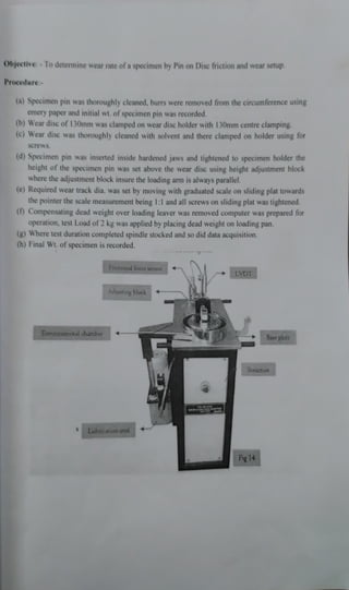
Factional torce sensor
LVDT
Adjusting block
Enveronunental chamber Base plate
Strucnire
Lubncation unut
Fig 14
2. Construction:
TR-20L -
PDNM, Pin on disc wear and friction monitor represent a substantial advance
interms of simplicity and convenience of operation ease of specimen clamping and accuracy of
measurement both wear and friction force the equipment is designed to apply load up to
200
and speed starting from 200 to 2000 RPM, provision is made only to conduct tests under dry and
heated conditions. This apparatus facilities of friction and wear characteristics in sliding contacts
underdifferent test conditions sliding occurs between the stationary pin and a rotating disc the
normal load, rotational speed and wear track dia. Can be varied to suit test conditions tangential
frictional force and wear are mounted with electronic sensors and recorded on PC. These
parameters are available as frictions of load and speed.
War dac
Loadung leva
Fg31
Sanpie pun
Fig 30
Fg 33
Holder for specunen pio
Test Parameter Details
Speed 400 RPM (200 RPM to 2000 RPM)
Normal Load (5-200 N)2 kg
Friction Force 0- 200 N Max
Wear 2mm
Wear Track Diameter Up to 140mm (130mm)
Pin 1Omm
165mmX8mm thick EN-31 hardened to 60HRc, ground to
surface roughness 1.6 Ra Win ducom 2010
Wear Disc
3. Sensors:-Sensorsare used to measure the test parameters on this machine.
(a) LVDT (Linear Variable Differential Transducer):- A LVDT measures wear between
specimen pin and disc for this the sensor is mounted at exactly same distance or
specimen trom pivot point to get equal (1:1) lever ratio. The plunger ofsensor resets on
hardened pin projection from lever, during wear occurs the loading lever lifts in upward
direction pushing the plunger, this plunger movement as on indication of wear rate is
sensed by LVDT as the plunger lefts up, and this movement is displayed as wear on
controller. Least count of LVDT is I micrometer the max wear measured is between+
2mm.
(b)Frietion force: The friction between pin and rotating
mounted on a bracket at a distance equal to the distance between specimen and pivot. A
beam type load cell with max
capacity of 20 kg is used to measure frictional force up to
200 N. The load cell with bracket is fixed on sliding plate and it moves along with
sliding plate while setting wear track diameter. It is a strain gauge type of load cell;
primarily a column of corrosion resistant super alloy of high tensile strength steel that
deforms very minutely under load. The deformation is sensed by foil type strain gauges
bonded Wheatstone Bridge.
(c) Temperature Sensor: -
2 No's of K- type thermocouple are provide to measure pin &
chamber temperatures. One K- type thermocouple is placed near the radiation heater to
measure chamber temperature & another K- type thermocouple is inserted through the
hole on
specimen pin to measure pin temperature. The sensor tip is exposed to free
inners surface of chamber. The chamber temperature is controlled by PID (Proportional
Integral Derivation) fitted on controller; the set value on PID sereen is compared with
measured value by sensor and corresponding power to heater is regulated to min or max
depending on the difference of measured value.
isc is measured by load cell
(d) Proximity Sensor: -
The spindle speed is measured by proximity sensor, for this an
RPM sensor (indexing plate) with slots on circumference is fixed to bottom of spindle&
rotated with it. The sensor is mounted perpendicular to it on a bracket; signal is
generated when sensor disc approaches the active surface with in the specified switching
distance. The sensor works in contactless fashion and do not require any sensing
mechanisms.
An inductive proximity sensor is used, thus it can detect wide range of metallic targets
and is mechanically wear free.
4. Spindle assembly Side panel for
Pac y connectorss
sensc
AC motor with
belt dave
Wze jack
to cool pinde
ACdaive
Fig I5
Fig 16
Precaution: -
1. The sample preparation plays a very important role in performing pin on disc wear
test. The flatness and surface roughness are same
parameters which are a few to
mention.
2. The alignment (perpendicularity) between sample holder and the counter disc axis
was
carefully checked to ensure specimen cross SXN contacts the disc appropriately.
3. The pulley alignment loading lever, LVDT position and weigh hanger is checked
before the test to ensure normal load acts properly because it affects coefticient of
friction.
4. The set up (disc) was cleaned properly with solvent since left over debris from
previous test can cause faulty info.
5. Some time was allowed (5min) for electronic components of measured valve.
Result and Discussion
1. Coefficient of friction initially increases very fast and then decreases. Then it reaches a
constant valve and maintains it
2. Wear rate instantly increase & then increases gradually.
3. Pin temperature increases almost linearly.
. A . . . . . A .