Thông số kĩ thuật siemens rccb 5 sm
•
0 gefällt mir•422 views

Thông số kĩ thuật siemens rccb 5 sm

Empfohlen
Weitere ähnliche Inhalte
Was ist angesagt?
Was ist angesagt? (20)
Ähnlich wie Thông số kĩ thuật siemens rccb 5 sm
Ähnlich wie Thông số kĩ thuật siemens rccb 5 sm (20)
Mehr von Công ty cổ phần OKS | Tổng thầu thi công Nhà máy GMP, Tổng thầu thi công Nhà kho GSP
Mehr von Công ty cổ phần OKS | Tổng thầu thi công Nhà máy GMP, Tổng thầu thi công Nhà kho GSP (20)
Kürzlich hochgeladen
Kürzlich hochgeladen (20)
Thông số kĩ thuật siemens rccb 5 sm
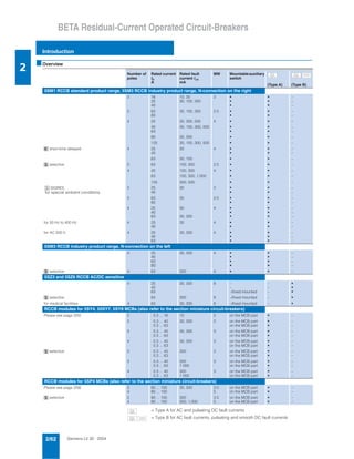
- 1. Siemens LV 30 · 20042/62 BETA Residual-Current Operated Circuit-Breakers Introduction 2 * This quantity or a multiple thereof can be ordered. ■Overview Number of poles Rated current In A Rated fault current IΔn mA MW Mountableauxiliary switch (Type A) (Type B) 5SM1 RCCB standard product range, 5SM3 RCCB industry product range, N-connection on the right 2 16 10, 30 2 • • – 25 30, 100, 300 • • – 40 • • – 2 63 30, 100, 300 2.5 • • – 80 • • – 4 25 30, 300, 500 4 • • – 40 30, 100, 300, 500 • • – 63 • • – 80 30, 300 • • – 125 30, 100, 300, 500 • • – æ short-time delayed 4 25 30 4 • • – 40 • • – 63 30, 100 • • – î selective 2 63 100, 300 2.5 • • – 4 40 100, 300 4 • • – 63 100, 300, 1,000 • • – 125 300, 500 • • – ‹ SIGRES, for special ambient conditions 2 25 30 2 • • – 40 • • – 2 63 30 2.5 • • – 80 • • – 4 25 30 4 • • – 40 • • – 63 30, 300 • • – for 50 Hz to 400 Hz 4 25 30 4 • • – 40 • • – for AC 500 V 4 25 30, 300 4 • • – 40 • • – 63 • • – 5SM3 RCCB industry product range, N-connection on the left 4 25 30, 300 4 • • – 40 • • – 63 • • – 80 • • – î selective 4 63 300 4 • • – 5SZ3 and 5SZ6 RCCB AC/DC sensitive 4 25 30, 300 8 – – • 40 – – • 63 –/fixed mounted – • î selective 63 300 8 –/fixed mounted – • for medical facilities 4 63 30, 300 8 –/fixed mounted – • RCCB modules for 5SY4, 55SY7, 5SY8 MCBs (also refer to the section miniature circuit-breakers) Please see page 2/55 2 0.3 ... 16 10 2 on the MCB part • – 2 0.3 ... 40 30, 300 2 on the MCB part • – 0.3 ... 63 on the MCB part • – 3 0.3 ... 40 30, 300 3 on the MCB part • – 0.3 ... 63 on the MCB part • – 4 0.3 ... 40 30, 300 3 on the MCB part • – 0.3 ... 63 on the MCB part • – î selective 2 0.3 ... 40 300 2 on the MCB part • – 0.3 ... 63 on the MCB part • – 3 0.3 ... 40 300 3 on the MCB part • – 0.3 ... 63 1 000 on the MCB part • – 4 0.3 ... 40 300 3 on the MCB part • – 0.3 ... 63 1 000 on the MCB part • – RCCB modules for 5SP4 MCBs (also refer to the section miniature circuit-breakers) Please see page 2/56 2 80 ... 100 30, 300 3.5 on the MCB part • – 4 80 ... 100 5 on the MCB part • – î selective 2 80 ... 100 300 3.5 on the MCB part • – 4 80 ... 100 300, 1,000 5 on the MCB part • – = Type A for AC and pulsating DC fault currents = Type B for AC fault currents, pulsating and smooth DC fault currents
- 2. Siemens LV 30 · 2004 2/63 BETA Residual-Current Operated Circuit-Breakers Introduction 2 * This quantity or a multiple thereof can be ordered. ■Technical specifications Definitions 1 MW = modular width of 18 mm N-type = device mounting depth of 55 mm Depth 70 mm = device mounting depth of 70 mm Standards IEC/EN 61008, VDE 0664 Part 10, IEC/EN 61543, VDE 0664 Part 30, VDE 0664 Part 100 IEC/EN 61009, VDE 0664 Part 20 Designs 2-pole, 3-pole and 4-pole Rated voltages Un AC V 125 - 230 50 - 60 Hz 230 - 400 50 - 60 Hz, 50 - 400 Hz 500 50 - 60 Hz Rated currents In A 16, 25, 40, 63, 80, 125 Rated fault currents IΔn mA 10, 30, 100, 300, 500, 1 000 Enclosure Gray molded plastic (RAL 7035) Terminals Tunnel terminals at both ends with wire protection, lower combined terminal for simultaneous connection of busbars and conductors Conductor cross- section mm2 Recommended ter- minal tightening torque Nm for 2 MW at In = 16 A, 25 A, 40 A 1.0 ... 16 2.5 ... 3.0 for 2.5 MW at In = 63 A, 80 A 1.5 ... 25 2.5 ... 3.0 for 4 MW at In = 25 A, 40 A, 63 A, 80 A 1.5 ... 25 2.5 ... 3.0 at In = 125 A 2.5 ... 50 3.0 ... 3.5 Tunnel terminals with wire protection with RCCB modules (see pages 2/55, 2/56) up to In = 63 A 1.0 ... 25 2.5 ... 3.0 up to In = 80/100 A 6.0 ... 35 3.0 ... 3.5 Screw-head terminals for auxiliary switches 0.75 ... 2.5 0.6 ... 0.8 Supply connection Either top or bottom Mounting position As required Degree of protection IP20 acc. to DIN VDE 0470 Part 1 IP40 when mounted in distribution boards IP54 when mounted in plastic casing Touch protection Protection against contact with fingers or the back of the hand acc. to DIN VDE 0106 Part 100 Minimum operating voltage for test function operation AC V For RCCB 16 A - 80 A 125 A 100 195 with RCCB modules (see pages 2/55, 2/56) up to In = 63 A, 4-pole up to In = 63 A, 2- and 3-pole up to In = 80/100 A 100 195 100 Device service life > 10 000 operations (electrical and mechanical test cycle according to regulations) Storage temperature °C -40 ... +75 Ambient temperature °C -5 ... +45, for designs with the symbol : -25 ... +45 Resistance to climate 28 cycles (55 °C; 95 % rel. humidity) acc. to IEC 60068-2-30 Free of CFC and silicon yes -25
- 3. Siemens LV 30 · 20042/64 BETA Residual-Current Operated Circuit-Breakers N-type, 16 A to 80 A 55 mm mounting range RCCB Standard Product Range 2 * This quantity or a multiple thereof can be ordered. ■Area of application • Device standards: IEC/EN 61008-1 (VDE 0664, Part 10), IEC/EN 61008-2-1 (VDE 0664, Part 11) • Un 230/400 V; 50 to 60 Hz; Un 230/400 V; 50 to 400 Hz; applicable in networks of up to AC 240/415 V • Un 500/V; 50 to 60 Hz applicable in AC 500 V networks • Terminals with wire protection can be used for direct busbar mounting at the bottom with devices with modular-size termi- nals, e.g. with 5SX2 and 5SX4 MCBs • Retrofitting of auxiliary switches on the right hand side of the casing • Switch handle and test button can be locked • Designs î for selective disconnection æ for short-time delayed disconnection • Type of surge current 8/20 acc. to DIN VDE 0432 Part 2 surge strength instananeous > 1 kA, æ > 3 kA, î > 5 kA For supplementary components and accessories, please see page 2/66. Device designs with terminals located at the left hand side for the neutral conductor are available on request. ■Selection and ordering data Maximum permissible short-circuit back- up fuse Rated current Rated fault current MW Design DC Order No. Pack. unit* Weight per unit approx. In IΔn A mA kg For AC and pulsating DC fault currents (Type A) AC 125 V to 230 V; 50 Hz to 60 Hz 2-pole 16 10 2 A 5SM1 111-6 1 0.218 16 30 A 5SM1 311-6 1 0.218 25 30 A 5SM1 312-6 1 0.218 40 A 5SM1 314-6 1 0.218 25 100 A 5SM1 412-6 1 0.218 40 A 5SM1 414-6 1 0.218 25 300 A 5SM1 612-6 1 0.218 40 A 5SM1 614-6 1 0.218 63 30 2.5 A 5SM1 316-6 1 0.300 80 A 5SM1 317-6 1 0.300 63 100 A 5SM1 416-6 1 0.280 80 A 5SM1 417-6 1 0.280 63 300 A 5SM1 616-6 1 0.280 80 A 5SM1 617-6 1 0.280 63 300 2.5 î A 5SM1 616-8 1 0.280 AC 230 V to 400 V; 50 Hz to 60 Hz 4-pole 25 30 4 A 5SM1 342-6 1 0.473 40 A 5SM1 344-6 1 0.473 63 A 5SM1 346-6 1 0.473 80 A 5SM1 347-6 1 0.473 40 100 A 5SM1 444-6 1 0.483 63 A 5SM1 446-6 1 0.509 25 300 A 5SM1 642-6 1 0.473 40 A 5SM1 644-6 1 0.473 63 A 5SM1 646-6 1 0.473 80 A 5SM1 647-6 1 0.473 25 500 A 5SM1 742-6 1 0.473 40 A 5SM1 744-6 1 0.473 63 A 5SM1 746-6 1 0.473 40 100 4 î A 5SM1 444-8 1 0.473 40 300 î A 5SM1 644-8 1 0.473 63 î A 5SM1 646-8 1 0.473 63 1 000 î A 5SM1 846-8 1 0.473 63 A 10 000 I2_05982c 1 N 2 N T 100 A 10 000 100 A 10 000 100 A 10 0001 53 N 2 4 6 N T I 2 _ 0 5 9 7 7 d 100 A 10 000 (Type A) -25
- 4. Siemens LV 30 · 2004 2/65 BETA Residual-Current Operated Circuit-Breakers RCCB Standard Product Range N-type, 16 A to 80 A 55 mm mounting range 2 * This quantity or a multiple thereof can be ordered. ■Selection and ordering data 1) Approval acc. to IEC/EN 61008 (VDE 0664) is only possible up to 440 V. For supplementary components and accessories, please see page 2/66. ■Benefits Thanks to the leakage current measurement unit, the rated fault current for the RCCB can be selected systematically and unin- tended trippings will be avoided. The measured leakage current should not be higher than a maximum of 1/3 of the rated fault current of the RCCB. If this condition is not given due to the rated current required for the protective measures for the RCCB, cor- rective measures must be taken at the respective operating equipment which generates the leakage current. The detection of causes for the unintended tripping of the RCCB is considerably simplified, especially with regard to large systems. • Rated voltage: up to AC 500 V; 50 Hz to 60 Hz • For measuring leakage currents of up to 300 mA in electrical systems • Using the enclosed calibration curve, a voltmeter with an inter- nal resistance of > 1 MΩ/V can determine the leakage current. Measuring range for AC voltage: Ueff: 1 mV - 2 V • Leakage currents are currents, which, during uninterrupted operation, leak off the PE conductor or other ground connec- tions. As a result, the difference of the currents flowing to and from the device will be higher than zero thanks to the RCCB. If the tripping current of the residual-current operated circuit- breaker is then reached, it will trip since leakage currents are similarly recorded and evaluated as fault currents. • The leakage current measurement unit detects the static leak- age currents flowing. The device records and evaluates the currents like the RCCB and thus provides a direct statement on the extent to which the RCCB has already been pre-loaded. Gossen-Metrawatt offers suitable test devices for RCCB function tests and for testing protective measures. Information is available at: Gossen-Metrawatt GmbH www.gmc-instruments.com Thomas-Mann-Str. 16-20 email: info@gmc-instruments.com D-90471 Nuremberg, Germany Tel. +49 (0)911/8602 111 Fax +49 (0)911/8602 777 Maximum permissible short-circuit back- up fuse Rated current Rated fault current MW Design DC Order No. Pack. unit* Weight per unit approx. In IΔn A mA kg For AC and pulsating DC fault currents (Type A) AC 230 V to 400 V; 50 Hz to 400 Hz 4-pole 25 30 4 A 5SM1 342-6KK03 1 0.473 40 A 5SM1 344-6KK03 1 0.473 25 30 4 æ A 5SM1 342-6KK01 1 0.473 40 æ A 5SM1 344-6KK01 1 0.473 63 100 æ A 5SM1 446-6KK01 1 0.473 AC 500 V1) ; 50 Hz to 60 Hz 4-pole 25 30 4 A 5SM1 352-6 1 0.515 40 A 5SM1 354-6 1 0.515 63 A 5SM1 356-6 1 0.515 25 300 A 5SM1 652-6 1 0.515 40 A 5SM1 654-6 1 0.515 63 A 5SM1 656-6 1 0.515 80 A 10 0001 53 N 2 4 6 N T I 2 _ 0 5 9 7 7 d 100 A 10 000 63 A 10 000 ■Selection and ordering data Rated current Rated fault current MW DC Order No. Pack. unit* Weight per unit approx. In IΔn A mA kg 5SM1 930 leakage current measurement unit AC 500 V; 50 Hz to 60 Hz, 4-pole 63 0-300 4 A 5SM1 930-0 1 0.3101 53 N 2 4 6 N I2_07078a V ≥ 1 MΩ/V (Type A) -25
- 5. Siemens LV 30 · 20042/66 BETA Residual-Current Operated Circuit-Breakers Supplementary components 55 mm mounting depth RCCB Standard Product Range 2 * This quantity or a multiple thereof can be ordered. ■Area of application • 1 auxiliary contact can be retrofitted individually • Mounting with factory-installed clips • Max. contact load: AC 6 A/230 V DC 1 A/220 V • Short-circuit protection ensured by circuit-breakers with characteristic B or C with In = 6 A or fuse gL 6 A • Indication of the RCCB switching state - AS: ON/OFF • Can be connected to the instabus EIB and the AS interface- Bus or the PROFIBUS via binary inputs For further busbars, please see page 2/37. input instabus EIB I2_07482c RCCB AS A ■Selection and ordering data MW DC Order No. Pack. unit* Weight per unit approx. kg Auxiliary switches (AS) 1 NO + 1 NC 0.5 A 5SW3 000 1 0.042 2 NC 0.5 A 5SW3 001 1 0.042 2 NO 0.5 A 5SW3 002 1 0.042 21 13 22 14 21 11 22 12 23 13 24 14 ■Selection and ordering data Length DC Order No. Pack. unit* Weight per unit approx. mm kg Locking device sealable and lockable 4.5 mm lock hasp diameter A 5SW3 003 10 0.008 Padlock for 5SW3 003 locking device A 5ST3 802 1 0.027 Locking device with padlock consisting of 5ST3 003 locking device and 5ST3 802 padlock A 5SW3 012 1 set 0.035 Cu busbar 16 mm2 for busbar mounting of 5SM1 RCCBs, of RCCBs with 5SX2 and 5SX4 miniature circuit-breakers or 5TE7 switch disconnectors with Ie 40 A to 100 A 2-phase 210 A 5ST2 143 10 0.154 1 000 A 5ST2 152 5 0.692 3-phase 210 A 5ST2 144 10 0.231 1 000 A 5ST2 153 10 1.100 3-phase + N 210 A 5ST2 145 10 0.315 1 000 A 5ST2 154 5 1.498 End caps required to insulate the ends of cut-to-length busbars 1- and 2-phase A 5ST2 155 10 0.013 3- and 4-phase A 5ST2 156 10 0.017 3-phase busbar for a 4-pole 5SM1 RCCB with 8 miniature circuit-breakers 3/N + 8 connections A 5ST2 424 5 0.091 Accessories for 55 mm mounting depth
- 6. Siemens LV 30 · 2004 2/67 BETA Residual-Current Operated Circuit-Breakers AC/DC Sensitive N-type, 25 A to 63 A 55 mm mounting depth 2 * This quantity or a multiple thereof can be ordered. ■Area of application • Device standards: IEC/EN 61008-1(VDE 0664, Part 10), IEC 60755, VDE 0664 Part 100 • Un 230/400 V; 50 to 60 Hz; applicable in networks: AC 240/415 V • For AC fault currents, pulsating and smooth DC fault currents • For designs with fixed mounted auxiliary switches contact 1 NO + 1 NC, AC 6 A/230 V, DC 1 A/220 V terminals for conductor cross sections of up to 2.5 mm2 • Design î for selective disconnection • Type of surge current 8/20 acc. to DIN VDE 0432 surge strength: instantaneous > 1 kA î > 5 kA • These devices are used in systems where, in addition to AC and pulsating DC fault currents, smooth or almost smooth DC fault currents may also occur (e.g. with B6 bridge connection in devices such as frequency converters and medical de- vices). ■Selection and ordering data Maximum permissible short-circuit back-up fuse Rated current Rated fault current MW Design DC Order No. Pack. unit* Weight per unit approx. In IΔn A mA kg For AC fault currents, pulsating and smooth DC (type B) AC 230 V/400 V; 50 Hz to 60 Hz; 4-pole 25 30 8 A 5SZ3 426-0KG00 1 0.746 40 A 5SZ3 446-0KG00 1 0.746 63 A 5SZ3 466-0KG00 1 0.746 25 300 8 A 5SZ6 426-0KG00 1 0.706 40 A 5SZ6 446-0KG00 1 0.706 63 A 5SZ6 466-0KG00 1 0.706 63 300 8 î A 5SZ6 468-0KG00 1 0.706 • with auxiliary switch, fixed mounted 63 30 8.5 A 5SZ3 466-0KG30 1 0.750 63 300 A 5SZ6 466-0KG30 1 0.750 63 300 8.5 î A 5SZ6 468-0KG30 1 0.765 AC 230 V/400 V; 50 Hz to 60 Hz; 4-pole for medical facilities (e.g. x-ray generators) 63 30 81 A 5SZ3 466-0KG05 1 0.710 63 300 A 5SZ6 466-0KG05 1 0.710 • with auxiliary switch, fixed mounted 63 30 8.5 A 5SZ3 466-0KG35 1 0.750 63 300 A 5SZ6 466-0KG35 1 0.750 1 53 N 2 4 6 N TI 2 _ 0 5 9 7 6 c 63 A 6 000 VDE (Type B) -25
- 7. Siemens LV 30 · 20042/68 BETA Residual-Current Operated Circuit-Breakers 16 A to 80 A 70 mm mounting depth RCCB Industry Product Range 2 * This quantity or a multiple thereof can be ordered. ■Area of application • Device standards: IEC/EN 61008-1 (VDE 0664, Part 10), IEC/EN 61008-2-1 (VDE 0664, Part 11) • Un 230/400 V; 50 to 60 Hz; Un 230/400 V; 50 to 400 Hz; applicable in networks of up to: AC 240/415 V Un AC 500 V; 50 to 60 Hz applicable in networks: AC 500 V • Terminals with wire protection can be used for direct busbar mounting at the bottom with modular-size terminals, e.g. with 5SY4, 5SY7 miniature-circuit breaker ranges. • Retrofitting of auxiliary switches on the right hand side of the enclosure • Designs: ‹ SIGRES, for special ambient conditions (e.g. indoor swimming pools, agriculture) î for selective disconnection æ for short-time delayed disconnection • Type of surge current 8/20 acc. to DIN VDE 0432 Part 2 surge strength instantaneous > 1 kA ‹ > 1 kA æ > 3 kA î > 5 kA ■Selection and ordering data Maximum permissible short-circuit back-up fuse Rated current Rated fault current MW Design DC Order No. Pack. unit* Weight per unit approx. In IΔn A mA kg For AC and pulsating DC fault currents, N-connection on the right AC 125 V to 230 V; 50 Hz to 60 Hz; 2-pole 16 10 2 A 5SM3 111-6 1 0.230 16 30 A 5SM3 311-6 1 0.230 25 A 5SM3 312-6 1 0.230 40 A 5SM3 314-6 1 0.230 25 100 A 5SM3 412-6 1 0.230 40 A 5SM3 414-6 1 0.230 25 300 A 5SM3 612-6 1 0.230 40 A 5SM3 614-6 1 0.230 25 30 ‹ X 5SM3 312-6KK12 1 0.230 40 ‹ X 5SM3 314-6KK12 1 0.230 63 30 2.5 A 5SM3 316-6 1 0.320 80 A 5SM3 317-6 1 0.320 63 100 A 5SM3 416-6 1 0.320 80 A 5SM3 417-6 1 0.320 63 300 A 5SM3 616-6 1 0.320 80 A 5SM3 617-6 1 0.320 63 30 ‹ X 5SM3 316-6KK12 1 0.320 80 ‹ X 5SM3 317-6KK12 1 0.320 63 100 î A 5SM3 416-8 1 0.320 63 300 î A 5SM3 616-8 1 0.320 AC 230 V to 400 V; 50 Hz to 60 Hz; 4-pole 25 30 4 A 5SM3 342-6 1 0.515 40 A 5SM3 344-6 1 0.515 63 A 5SM3 346-6 1 0.515 80 A 5SM3 347-6 1 0.515 40 100 A 5SM3 444-6 1 0.515 63 A 5SM3 446-6 1 0.515 25 300 A 5SM3 642-6 1 0.515 40 A 5SM3 644-6 1 0.515 63 A 5SM3 646-6 1 0.515 80 A 5SM3 647-6 1 0.515 25 500 A 5SM3 742-6 1 0.515 40 A 5SM3 744-6 1 0.515 63 A 5SM3 746-6 1 0.515 25 30 ‹ X 5SM3 342-6KK12 1 0.515 40 ‹ X 5SM3 344-6KK12 1 0.515 63 ‹ D 5SM3 346-6KK12 1 0.522 63 300 ‹ X 5SM3 646-6KK12 1 0.515 40 100 î A 5SM3 444-8 1 0.515 63 î A 5SM3 446-8 1 0.522 40 300 î A 5SM3 644-8 1 0.515 63 î A 5SM3 646-8 1 0.515 63 1 000 î A 5SM3 846-8 1 0.515 I2_05982c 1 N 2 N T 63 A 10 000 100 A 10 000 1 53 N 2 4 6 N T I 2 _ 0 5 9 7 7 d 100 A 10 000 (Type A) -25
- 8. Siemens LV 30 · 2004 2/69 BETA Residual-Current Operated Circuit-Breakers RCCB Industry Product Range 16 A to 80 A 70 mm mounting depth 2 * This quantity or a multiple thereof can be ordered. ■Selection and ordering data Maximum permissible short-circuit back-up fuse Rated current Rated fault current MW Design DC Order No. Pack. unit* Weight per unit approx. In IΔn A mA For AC and pulsating DC fault currents, N-connection on the left AC 230 V to 400 V; 50 Hz to 60 Hz 4-pole 25 30 4 C 5SM3 342-6KL 1 0.515 40 C 5SM3 344-6KL 1 0.515 63 C 5SM3 346-6KL 1 0.515 80 C 5SM3 347-6KL 1 0.515 25 300 4 C 5SM3 642-6KL 1 0.515 40 C 5SM3 644-6KL 1 0.515 63 C 5SM3 646-6KL 1 0.515 80 C 5SM3 647-6KL 1 0.515 63 300 4 î C 5SM3 646-8KL 1 0.515 For AC and pulsating DC fault currents, N-connection on the right AC 230 V to 400 V; 50 Hz to 400 Hz 4-pole 25 30 4 A 5SM3 342-6KK03 1 0.515 40 A 5SM3 344-6KK03 1 0.515 25 30 4 æ A 5SM3 342-6KK01 1 0.515 40 æ A 5SM3 344-6KK01 1 0.515 63 30 æ A 5SM3 346-6KK01 1 0.515 63 100 æ A 5SM3 446-6KK01 1 0.515 AC 500 V1) ; 50 Hz to 60 Hz; 4-pole 25 30 4 A 5SM3 352-6 1 0.515 40 A 5SM3 354-6 1 0.515 63 A 5SM3 356-6 1 0.515 25 300 A 5SM3 652-6 1 0.515 40 A 5SM3 654-6 1 0.515 63 A 5SM3 656-6 1 0.515 1) Approval acc. to IEC/EN 61008 (VDE 0664) is only possible up to 440 V. 1 53N 2 4 6N T I2_10730 100 A 10 000 80 A 10 000 1 53 N 2 4 6 N T I 2 _ 0 5 9 7 7 d 100 A 10 000 63 A 10 000
- 9. Siemens LV 30 · 20042/70 BETA Residual-Current Operated Circuit-Breakers 125 A 70 mm mounting depth RCCB Industry Product Range 2 * This quantity or a multiple thereof can be ordered. ■Area of application • Device standards: IEC/EN 61008-1 (VDE 0664, Part 10), IEC/EN 61008-2-1 (VDE 0664, Part 11) • Un 230/400 V; 50 to 60 Hz; applicable in networks of up to: AC 240/415 V • Retrofitting of auxiliary switches at the right hand side of the casing • Switch handle and test button can be locked • 4-pole (three phases with active neutral conductor) • Design: î for selective disconnection ■Selection and ordering data Maximum permissible short-circuit back-up fuse Rated current Rated fault current MW Design DC Order No. Pack. unit* Weight per unit approx. In IΔn A mA kg For AC and pulsating DC fault currents, N-connection on the right AC 230 V to 400 V; 50 Hz to 60 Hz; 4-pole 125 30 4 A 5SM3 345-6 1 0.300 125 100 A 5SM3 445-6 1 0.533 125 300 A 5SM3 645-6 1 0.536 125 500 A 5SM3 745-6 1 0.300 125 300 4 î A 5SM3 645-8 1 0.542 125 500 î A 5SM3 745-8 1 0.527 Example for 4-pole 5SM2 8... RCCB module 5SM2 RCCB module for miniature circuit-breaker Supplementary components for 5SY and 5SP4 miniature circuit-breakers for the following rated currents: 0.3 ... 16 0.3 ... 40 0.3 ... 63 80 ... 100 Please see pages 2/55 and 2/56 2 4 6 N T I 2 _ 0 6 2 3 2 c 1 53 N 125 A 10 000 1 3 5 7 ( N )2 4 6 8 ( N ) 2 / 1 4 / 3 6 / 5 8 / 7 ( N ) I 2 _ 0 7 8 1 9 a
- 10. Siemens LV 30 · 2004 2/71 BETA Residual-Current Operated Circuit-Breakers RCCB Industry Product Range Supplementary components 70 mm mounting depth 2 * This quantity or a multiple thereof can be ordered. ■Area of application • 1 auxiliary contact can be retrofitted individually • Mounting with factory-installed clips • Max. contact load: - for 5SW3 30., 6 A/AC 230 V, 1 A/DC 220 V - for 5SW3 330, 5 A/AC 230 V, 0.5 A/DC 220 V • Short-circuit protection ensured by circuit-breakers with char- acteristic B or C with In = 6 A or fuse gL 6 A • Indication of the RCCB switching state: AS: ON/OFF • Can be connected to the instabus EIB and the AS interface- Bus or the PROFIBUS via binary inputs ■Selection and ordering data i n p u t i n s t a b u s E I B I 2 _ 0 7 8 4 9 a R C C B A S MW DC Order No. Pack. unit* Weight per unit approx. kg Auxiliary switches for residual-current operated circuit-breakers of up to 80 A Auxiliary switches (AS) 1 NO + 1 NC 0.5 A 5SW3 300 1 0.042 2 NC 0.5 A 5SW3 301 1 0.042 2 NO 0.5 A 5SW3 302 1 0.042 Auxiliary switch for residual-current operated circuit-breakers 125 A Auxiliary switch (AS) 1 NO + 1 NC 0.5 A 5SW3 330 1 0.040 21 13 22 14 21 11 22 12 23 13 24 14 23 11 24 12
- 11. Siemens LV 30 · 20042/72 BETA Residual-Current Operated Circuit-Breakers Accessories 70 mm mounting depth RCCB Industry Product Range 2 * This quantity or a multiple thereof can be ordered. ■Selection and ordering data For further busbars, please see page 2/60. Design DC Order No. Pack. unit* Weight per unit approx. kg Locking device for RCCBs up to 80 A sealable and lockable 4.5 mm lock hasp diameter A 5SW3 303 1 0.008 Padlock for 5SW3 303 locking device A 5ST3 802 1 0.027 Locking device with padlock consists of 5ST3 303 locking device and 5ST3 802 padlock A 5SW3 312 1 set 0.035 Cu busbars 16 mm2 for busbar mounting of 5SM3 RCCBs with each other using 5SY7 miniature circuit-breakers Fully insulated: Length 214 mm 2-phase A 5ST3 704 25 0.060 2-phase + AS A 5ST3 706 25 0.060 3-phase A 5ST3 708 25 0.100 3-phase for a 4-pole 5SM3 RCCB (N-connection on the right) with 8 miniature circuit- breakers 3/N + 8 connections A 5ST3 717 25 0.150 Without end caps Length 1016 mm 2-phase A 5ST3 705 20 0.290 2-phase + AS A 5ST3 707 20 0.290 3-phase A 5ST3 710 20 0.430 End caps for lateral insulation of cut-to-length busbars 2- and 3-phase A 5SH5 514 10 0.001 7