Kia SRS Airbag System General Safety Information
•
0 gefällt mir•65 views

The document provides safety precautions and instructions for working on airbag systems. It describes storing removed airbags properly to prevent damage, carefully inspecting parts before installation, and turning off the ignition and disconnecting the battery before working to prevent accidental deployment. It also lists special service tools needed for tasks like deploying airbags and checking wiring harnesses.

Empfohlen
Empfohlen
Weitere ähnliche Inhalte
Ähnlich wie Kia SRS Airbag System General Safety Information
Ähnlich wie Kia SRS Airbag System General Safety Information (12)
Mehr von OBD Codex
Mehr von OBD Codex (20)
Kürzlich hochgeladen
Kürzlich hochgeladen (20)
Kia SRS Airbag System General Safety Information
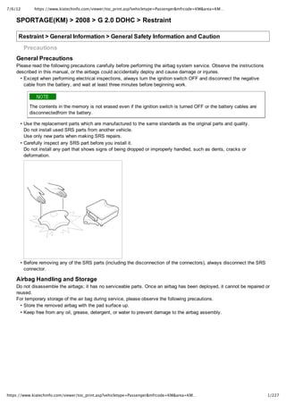
- 1. 7/6/12 https://www.kiatechinfo.com/viewer/toc_print.asp?vehicletype=Passenger&mfrcode=KM&area=KM… 1/227 https://www.kiatechinfo.com/viewer/toc_print.asp?vehicletype=Passenger&mfrcode=KM&area=KM… SPORTAGE(KM) > 2008 > G 2.0 DOHC > Restraint Restraint > General Information > General Safety Information and Caution Precautions General Precautions Please read the following precautions carefully before performing the airbag system service. Observe the instructions described in this manual, or the airbags could accidentally deploy and cause damage or injuries. • Except when performing electrical inspections, always turn the ignition switch OFF and disconnect the negative cable from the battery, and wait at least three minutes before beginning work. The contents in the memory is not erased even if the ignition switch is turned OFF or the battery cables are disconnectedfrom the battery. • Use the replacement parts which are manufactured to the same standards as the original parts and quality. Do not install used SRS parts from another vehicle. Use only new parts when making SRS repairs. • Carefully inspect any SRS part before you install it. Do not install any part that shows signs of being dropped or improperly handled, such as dents, cracks or deformation. • Before removing any of the SRS parts (including the disconnection of the connectors), always disconnect the SRS connector. Airbag Handling and Storage Do not disassemble the airbags; it has no serviceable parts. Once an airbag has been deployed, it cannot be repaired or reused. For temporary storage of the air bag during service, please observe the following precautions. • Store the removed airbag with the pad surface up. • Keep free from any oil, grease, detergent, or water to prevent damage to the airbag assembly.
- 2. 7/6/12 https://www.kiatechinfo.com/viewer/toc_print.asp?vehicletype=Passenger&mfrcode=KM&area=KM… 2/227 https://www.kiatechinfo.com/viewer/toc_print.asp?vehicletype=Passenger&mfrcode=KM&area=KM… • Store the removed airbag on secure, flat surface away from any high heat source (exceeding 85°C/185°F). • Never perform electrical inspections to the airbags, such as measuring resistance. • Do not position yourself in front of the airbag assembly during removal, inspection, or replacement. • Refer to the scrapping procedures for disposal of the damaged airbag. • Be careful not to bump or impact the SRS unit or the side impact sensors whenever the ignition switch is ON, wait at least three minutes after the ignition switch is turned OFF before begin work. • During installation or replacement, be careful not to bump (by impact wrench, hammer, etc.) the area around the SRS unit and the side impact sensor. The airbags could accidentally deploy and cause damage or injury. • After a collision in which the airbags were deployed, replace the front airbags and the SRS unit. After a collision in which the side airbag was deployed, replace the side airbag, the front impact sensor and side impact sensor on the side where the side airbag deployed and the SRS unit. After a collision in which the airbags or the side air bags did not deploy, inspect for any damage or any deformation on the SRS unit and the side impact sensors. If there is any damage, replace the SRS unit, the front impact sensor and/or the side impact sensors. • Do not disassemble the SRS unit, the front impact sensor or the side impact sensors • Turn the ignition switch OFF, disconnect the battery negative cable and wait at least three minutes before beginning installation or replacement of the SRS unit. • Be sure the SRS unit, the front impact sensor and side impact sensors are installed securely with the mounting bolts. • Do not spill water or oil on the SRS unit,or the front impact sensor or the side impact sensors and keep them away from dust. • Store the SRS unit, the front impact sensor and the side impact sensors in a cool (less than 104°F/40°C) and dry (less than 80% relative humidity, no moisture) area. Wiring Precautions SRS wiring can be identified by special yellow outer covering (except the SRS circuits under the front seats). Observe the instructions described in this section. • Never attempt to modify, splice, or repair SRS wiring. If there is an open or damage in SRS wiring, replace the harness.
- 3. 7/6/12 https://www.kiatechinfo.com/viewer/toc_print.asp?vehicletype=Passenger&mfrcode=KM&area=KM… 3/227 https://www.kiatechinfo.com/viewer/toc_print.asp?vehicletype=Passenger&mfrcode=KM&area=KM… • Be sure to install the harness wires so that they are not pinched, or interfere with other parts. • Make sure all SRS ground locations are clean, and grounds are securely fastened for optimum metaltometal contact. Poor grounding can cause intermittent problems that are difficult to diagnose. Precautions for Electrical Inspections • When using electrical test equipment, insert the probe of the tester into the wire side of the connector. Do not insert the probe of the tester into the terminal side of the connector, and do not tamper with the connector. • Use a ushaped probe. Do not insert the probe forcibly. • Use specificed service connectors for troubleshooting. Using improper tools could cause an error in inspection due to poor metal contact. Springloaded Lock Connector
- 4. 7/6/12 https://www.kiatechinfo.com/viewer/toc_print.asp?vehicletype=Passenger&mfrcode=KM&area=KM… 4/227 https://www.kiatechinfo.com/viewer/toc_print.asp?vehicletype=Passenger&mfrcode=KM&area=KM… Airbag Connector(I) Connecting 1. To reconnect, hold the pawlside connector half, and press on the back of the sleeveside connector half in the direction shown. As the two connectpr halves are pressed together, the sleeve (A) is pushed back by the pawl (C). Do not touch the sleeve. 2. When the connector halves are completely connected, the pawl is released, and the springloaded sleeve locks the connector. Airbag Connector(II)
- 5. 7/6/12 https://www.kiatechinfo.com/viewer/toc_print.asp?vehicletype=Passenger&mfrcode=KM&area=KM… 5/227 https://www.kiatechinfo.com/viewer/toc_print.asp?vehicletype=Passenger&mfrcode=KM&area=KM… Connecting Hold both connector halves and press firmly until the projection (C) of the sleeveside connector clicks to lock. WARNING LAMP ACTIVATION 1. Active fault or historical fault counter is greater or equal to 10 2. Normal or historical fault counter is less than 10 3. Loss of battery supply to the SRSCM : warning lamp turned on continuously. 4. Loss of internal operating voltage : warning lamp turned on continuously. 5. Loss of SRSCM operation : warning lamp turned on continuously. 6. SRSCM not connected : warning lamp turned on continuously through the shorting bar. 7. Reset by the Watchdog Trigger failure : warning lamp flashed or turned on continuously. TELLTALE LAMP ACTIVATION DESCRIPTION
- 6. 7/6/12 https://www.kiatechinfo.com/viewer/toc_print.asp?vehicletype=Passenger&mfrcode=KM&area=KM… 6/227 https://www.kiatechinfo.com/viewer/toc_print.asp?vehicletype=Passenger&mfrcode=KM&area=KM… The Telltale Lamp indicates the Passenger Airbag(PAB) enable disable status based on occupant status of passenger seat. If the passenger seat is occupied with child (or child seat), the Passenger Airbag is disabled and the Telltale Lamp is turned ON to inform the driver that the PAB is disabled. As soon as operating voltage is applied to the SRSCM ignition input, the SRSCM activates telltale lamp prove out. OCS will send an indeterminate status to the SRSCM as a default setting for passenger airbag deployment during the prove out period. After crash if OCS gets reset and sends the indeterminate status, the telltale lamp will be ON as long as the occupant status is in the indeterminate status. Occupant status information and telltale ststus are as below table. Occupant Status Telltale Status Indicator Passenger Airbag Empty(buckled) ON Disable Empty*unbuckled) OFF Disable Small ON Disable Large OFF Available Indeterminate ON Disable After ignition on, telltale lamp will turn on for 4 seconds and turn off for 3 seconds during the initialization phase and be turned off afterward until receive first valid suppression message from OCS system. Restraint > General Information > General Information Description The supplemental restraint system (SRS) is designed to supplement the seat belt to help reduce the risk or severity of injury to the driver and passenger by activating and deploying the driver, passenger, side airbag and belt pretensioner in certain frontal or side collisions. The SRS (Airbag) consists of : a driver side airbag module located in the center of the steering wheel, which contains the folded cushion and an inflator unit ; a passenger side airbag module located in the passenger side crash pad containsthe folded cushion assembled with inflator unit ; side airbag modules located in the driver and passenger seat contain the folded cushion and an inflator unit ; curtain airbag modules located inside of the headliner which contains folded cushions and inflator units. The Passenger Occupant classification System (OCS) utilizes bladder placed between the passenger seat cushion and suspension to measure the occupant’s loading force on the vehicle seat. Seat Track Position Sensor (STPS) located in driver and passenger seat interfaces with SRSCM and will help in determining whether to suppress either stage of a multistage airbag system. SRSCM is located under the center console. The impact sensing function of the SRSCM is carried out by electronic accelerometer that continuously measure the vehicle's acceleration and delivers a corresponding signal through amplifying and filtering circuitry to the microprocessor. SRSCM (SRS Control Module)
- 7. 7/6/12 https://www.kiatechinfo.com/viewer/toc_print.asp?vehicletype=Passenger&mfrcode=KM&area=KM… 7/227 https://www.kiatechinfo.com/viewer/toc_print.asp?vehicletype=Passenger&mfrcode=KM&area=KM… SRSCM will detect front impact with front impact sensor, and side impact with side impact sensor, and determine airbag module deployment. 1. DC/DC converter: DC/DC converter in power supply unit includes up/down transformer converter, and provide ignition voltage for 2 front airbag ignition circuits and the internal operation voltage of the SRSCM. If the internal operation voltage is below critical value setting, it will perform resetting. 2. Safety sensor: Safety sensor is located in airbag ignition circuit. Safety sensor will operate airbag circuit at any deployment condition and release airbag circuit safely at normal driving condition. Safety sensor is a double contact electromechanical switch that will close detecting deceleration above certain criteria. 3. Back up power supply: SRSCM has separate back up power supply, that will supply deployment energy instantly in low voltage condition or upon power failure by front crash. 4. Self diagnosis: SRSCM will constantly monitor current SRS operation status and detect system failure while vehicle power supply is on, system failure may be checked with trouble codes using scan tool. (HiScan) 5. Airbag warning lamp on: Upon detecting error, the module will transmit signal to SRSCM indicator lamp located at cluster. MIL lamp will indicate driver SRS error. Upon ignition key on, SRS lamp will turn on for about six seconds. 6. Trouble code registration: Upon error occurrence in system, SRSCM will store DTC corresponding to the error. DTC can be cleared only by HiScan. However, if an internal fault code is logged or if a crash is recorded thefault clearing should not happen. 7. Self diagnostic connector: Data stored in SRSCM memory will be output to HiScan or other external output devices through connector located below driver side crash pad. 8. Once airbag is deployed, SRSCM should not be used again but replaced. 9. SRSCM will determine whether passenger put on seat belt by the signal from builtin switch in seat belt buckle, and deploy front seat airbag at each set crash speed. 10. Side airbag deployment will be determined by SRSCM that will detect satellite sensor impact signal upon side crash, irrespective to seat belt condition. Restraint > General Information > Special Service Tools SPECIAL SERVICE TOOLS Tool(Number and Name) Illustration Use Deployment tool 0957A34100A Airbag deployment tool Deployment adapter 0957A38510 Use with deployment tool. (DAB,PAB)
- 8. 7/6/12 https://www.kiatechinfo.com/viewer/toc_print.asp?vehicletype=Passenger&mfrcode=KM&area=KM… 8/227 https://www.kiatechinfo.com/viewer/toc_print.asp?vehicletype=Passenger&mfrcode=KM&area=KM… Deployment adapter 0957A38100 Use with deployment tool. (SAB) Deployment adapter 0957A38500 Use with deployment tool. (CAB,BPT) Dummy 0957A38200 Simulator to check the resistance of each wiring harness Dummy adapter 0957A38300 Use with dummy (SAB) Dummy adapter 0957A2G000 Use with dummy (DAB,PAB,CAB,BPT) DAB : Driver Airbag PAB : Passenger Airbag SAB : Side Airbag CAB : Curtain Airbag BPT : Belt Pretensioner Restraint > General Information > Components and Components Location airbag system components
- 9. 7/6/12 https://www.kiatechinfo.com/viewer/toc_print.asp?vehicletype=Passenger&mfrcode=KM&area=KM… 9/227 https://www.kiatechinfo.com/viewer/toc_print.asp?vehicletype=Passenger&mfrcode=KM&area=KM… COMPONENTS LOCATION DRIVER AIRBAG (DAB) /PASSENGER AIRBAG (PAB)
- 10. 7/6/12 https://www.kiatechinfo.com/viewer/toc_print.asp?vehicletype=Passenger&mfrcode=KM&area=KM… 10/227 https://www.kiatechinfo.com/viewer/toc_print.asp?vehicletype=Passenger&mfrcode=KM&area=KM… SIDE AIRBAG (SAB) FRONT IMPACT SENSOR (FIS)
- 11. 7/6/12 https://www.kiatechinfo.com/viewer/toc_print.asp?vehicletype=Passenger&mfrcode=KM&area=KM… 11/227 https://www.kiatechinfo.com/viewer/toc_print.asp?vehicletype=Passenger&mfrcode=KM&area=KM… SEAT BELT PRETENSIONER (BPT) / SIDE IMPACT SENSOR (SIS) SRSCM
- 12. 7/6/12 https://www.kiatechinfo.com/viewer/toc_print.asp?vehicletype=Passenger&mfrcode=KM&area=KM… 12/227 https://www.kiatechinfo.com/viewer/toc_print.asp?vehicletype=Passenger&mfrcode=KM&area=KM… Restraint > General Information > Specifications SPECIFICATION ITEM SPECIFICATION Driver Airbag (DAB) Resistance (Ω) 1.5 ~ 5.7 Ω Passenger Airbag (PAB) Resistance (Ω) 1.5 ~ 5.7 Ω Side Airbag (SAB) Resistance (Ω) 1.5 ~ 5.7 Ω Curtain Airbag (CAB) Resistance (Ω) 1.5 ~ 5.7 Ω Seat Belt Pretensioner (BPT) Resistance (Ω) 1.5 ~ 5.7 Ω TIGHTENING TORQUES ITEM kgf.m N.m lb.ft Driver Airbag (DAB) 0.8 ~ 1.1 7.8 ~ 10.8 5.8 ~ 8.0 Passenger Airbag (PAB) 1.9 ~ 2.7 18.6 ~ 26.5 13.7 ~ 19.5 Side Airbag (SAB) 0.6 ~ 1 5.9 ~ 9.8 4.3 ~ 7.2 Curtain Airbag (CAB) 0.7 ~ 0.9 6.9 ~ 8.8 5.1 ~ 6.5 Seat Belt Lower Anchor bolt (BPT) 4.0 ~ 5.5 39 ~ 54 29 ~ 40 SRSCM Mounting Bolt 0.7 ~ 0.9 6.9 ~ 8.8 5.1 ~ 6.5 Front Impact Sensor (FIS) Mounting Bolt 0.9 ~ 1.1 8.8 ~ 10.8 6.5 ~ 8.0 Side Impact Sensor (SIS) Mounting Bolt 0.9 ~ 1.1 8.8 ~ 10.8 6.5 ~ 8.0 Restraint > Supplemental Restraint System Control Module (SRSCM) > Schematic Diagrams SYSTEM BLOCK DIAGRAM
- 15. 7/6/12 https://www.kiatechinfo.com/viewer/toc_print.asp?vehicletype=Passenger&mfrcode=KM&area=KM… 15/227 https://www.kiatechinfo.com/viewer/toc_print.asp?vehicletype=Passenger&mfrcode=KM&area=KM… SRSCM CONNECTOR TERMINAL PIN Function PIN Function 1 Shorting Bar 26 Warning Lamp 2 Shorting Bar 27 Battery Ground 3 Battery Supply(Vbat) 28 KLine Diagnostic 4 Seat Belt Pretensioner [FrontDriver] Low 29 Seat Belt Pretensioner [FrontPassenger] Low 5 Seat Belt Pretensioner [FrontDriver] High 30 Seat Belt Pretensioner [FrontPassenger] High 6 (2nd Stage) Passenger Airbag High 31 Buckle Switch [FrontPassenger] High 7 (2nd Stage) Passenger Airbag Low 32 Buckle Switch [FrontPassenger] Low 8 (2nd Stage) Driver Airbag Low 33 Buckle Switch [Driver] Low
- 16. 7/6/12 https://www.kiatechinfo.com/viewer/toc_print.asp?vehicletype=Passenger&mfrcode=KM&area=KM… 16/227 https://www.kiatechinfo.com/viewer/toc_print.asp?vehicletype=Passenger&mfrcode=KM&area=KM… 9 (2nd Stage) Driver Airbag High 34 Buckle Switch [Driver] High 10 Curtain Airbag [Passenger] High 35 Seat Track Position Sensor [Passenger] High 11 Curtain Airbag [Passenger] Low 36 Seat Track Position Sensor [Passenger] Low 12 Curtain Airbag [Driver] Low 37 Seat Track Position Sensor [Driver] Low 13 Curtain Airbag [Driver] High 38 Seat Track Position Sensor [Driver] High 14 Side Airbag [FrontPassenger] High 39 Side Impact Sensor [Passenger] High 15 Side Airbag [FrontPassenger] Low 40 Side Impact Sensor [Passenger] Low 16 Side Airbag [FrontDriver] Low 41 Side Impact Sensor [Driver] Low 17 Side Airbag [FrontDriver] High 42 Side Impact Sensor [Driver] High 18 43 Occupant Classification (OC) Sensor CAN Low 19 44 Occupant Classification (OC) Sensor CAN High 20 45 Front Impact Sensor [Passenger] High 21 46 Front Impact Sensor [Passenger] Low 22 (1st Stage) Passenger Airbag High 47 Front Impact Sensor [Driver] Low 23 (1st Stage) Passenger Airbag Low 48 Front Impact Sensor [Driver] High 24 (1st Stage) Driver Airbag Low 49 Crash Output 25 (1st Stage) Driver Airbag High 50 Telltale Warning Lamp Restraint > Supplemental Restraint System Control Module (SRSCM) > Troubleshooting HiScan check 1. Turn the ignition switch off. 2. Connect the HiScan Pro connector to the datalink connector located under the crash pad. 3. Connect the HiScan Pro power cable. 4. Turn the ignition switch on and power on the HiScan Pro. 5. Read DTCs. 6. Find and repair the trouble, and clear the DTCs using HiScan Pro. 7. Disconnect the HiScan Pro. DIAGNOSTIC TROUBLESHOOTING FLOW
- 17. 7/6/12 https://www.kiatechinfo.com/viewer/toc_print.asp?vehicletype=Passenger&mfrcode=KM&area=KM… 17/227 https://www.kiatechinfo.com/viewer/toc_print.asp?vehicletype=Passenger&mfrcode=KM&area=KM… DIAGNOSTIC TROUBLE CODES (DTC) CODE FAULT DESCRIPTION B1101 Battery Voltage too High B1102 Battery Voltage too Low B1326 Front Impact Sensor [Driver] Short to Ground B1327 Front Impact Sensor [Driver] Short to Battery B1328 Front Impact Sensor [Driver] Defect B1329 Front Impact Sensor [Driver] Communication Error B1330 Front Impact Sensor [Driver] Wrong ID B1331 Front Impact Sensor [Passenger] Short to Ground B1332 Front Impact Sensor [Passenger] Short to Battery B1333 Front Impact Sensor [Passenger] Defect B1334 Front Impact Sensor [Passenger] Communication Error B1335 Front Impact Sensor [Passenger] Wrong ID B1346 (1st Stage) Driver Airbag Resistance Too High B1347 (1st Stage) Driver Airbag Resistance Too Low B1348 (1st Stage) Driver Airbag Circuit Short to Ground B1349 (1st Stage) Driver Airbag Circuit Short to Battery B1352 (1st Stage) Passenger Airbag Resistance Too High B1353 (1st Stage) Passenger Airbag Resistance Too Low B1354 (1st Stage) Passenger Airbag Circuit Short to Ground B1355 (1st Stage) Passenger Airbag Circuit Short to Battery
- 18. 7/6/12 https://www.kiatechinfo.com/viewer/toc_print.asp?vehicletype=Passenger&mfrcode=KM&area=KM… 18/227 https://www.kiatechinfo.com/viewer/toc_print.asp?vehicletype=Passenger&mfrcode=KM&area=KM… B1361 Seat Belt Pretensioner [FrontDriver] Resistance Too High B1362 Seat Belt Pretensioner [FrontDriver] Resistance Too Low B1363 Seat Belt Pretensioner [FrontDriver] Circuit Short to Ground B1364 Seat Belt Pretensioner [FrontDriver] Circuit Short to Battery B1367 Seat Belt Pretensioner [FrontPassenger] Resistance Too High B1368 Seat Belt Pretensioner [FrontPassenger] Resistance Too Low B1369 Seat Belt Pretensioner [FrontPassenger] Circuit Short to Ground B1370 Seat Belt Pretensioner [FrontPassenger] Circuit Short to Battery B1378 Side Airbag [FrontDriver] Resistance Too High B1379 Side Airbag [FrontDriver] Resistance Too Low B1380 Side Airbag [FrontDriver] Circuit Short to Ground B1381 Side Airbag [FrontDriver] Circuit Short to Battery B1382 Side Airbag [FrontPassenger] Resistance Too High B1383 Side Airbag [FrontPassenger] Resistance Too Low B1384 Side Airbag [FrontPassenger] Circuit Short to Ground B1385 Side Airbag [FrontPassenger] Circuit Short to Battery B1396 Seat Track Position Sensor [Driver] Open or Short to Ground B1397 Seat Track Position Sensor [Driver] Short or Short to Battery B1398 Seat Track Position Sensor [Passenger] Open or Short to Ground B1399 Seat Track Position Sensor [Passenger] Short or Short to Battery B1400 Side Impact Sensor [FrontDriver] Defect B1401 Side Impact Sensor [FrontDriver] Short to Ground B1402 Side Impact Sensor [FrontDriver] Short to Battery B1403 Side Impact Sensor [FrontPassenger] Defect B1404 Side Impact Sensor [FrontPassenger] Short to Ground B1405 Side Impact Sensor [FrontPassenger] Short to Battery B1409 Side Impact Sensor [FrontDriver] Communication Error B1410 Side Impact Sensor [FrontPassenger] Communication Error B1414 Side Impact Sensor [FrontDriver] Wrong ID B1415 Side Impact Sensor [FrontPassenger] Wrong ID B1473 Side Curtain Airbag [Driver] Resistance Too High B1474 Side Curtain Airbag [Driver] Resistance Too Low B1475 Side Curtain Airbag [Driver] Circuit Short to Ground B1476 Side Curtain Airbag [Driver] Circuit Short to Battery B1477 Side Curtain Airbag [Passenger] Resistance Too High B1478 Side Curtain Airbag [Passenger] Resistance Too Low B1479 Side Curtain Airbag [Passenger] Circuit Short to Ground B1480 Side Curtain Airbag [Passenger] Circuit Short to Battery B1481 (2nd Stage) Driver Airbag Resistance Too High B1482 (2nd Stage) Driver Airbag Resistance Too Low B1483 (2nd Stage) Driver Airbag Circuit Short to Ground B1484 (2nd Stage) Driver Airbag Circuit Short to Battery B1485 (2nd Stage) Passenger Airbag Resistance Too High
- 19. 7/6/12 https://www.kiatechinfo.com/viewer/toc_print.asp?vehicletype=Passenger&mfrcode=KM&area=KM… 19/227 https://www.kiatechinfo.com/viewer/toc_print.asp?vehicletype=Passenger&mfrcode=KM&area=KM… B1486 (2nd Stage) Passenger Airbag Resistance Too Low B1487 (2nd Stage) Passenger Airbag Circuit Short to Ground B1488 (2nd Stage) Passenger Airbag Circuit Short to Battery B1489 Passenger Occupant Classification (OC) ECU failure B1490 Passenger Occupant Classification (OC) Sensor(Bladder) failure B1493 Passenger Occupant Classification (OC) Communication Error B1494 Passenger Occupant Classification (OC) Wrong ID B1495 Belt Tension Sensor failure B1521 Seat Belt Buckle Switch [Driver] Short or Short to Battery B1522 Seat Belt Buckle Switch [Driver] Open or Short to Ground B1523 Seat Belt Buckle Switch [FrontPassenger] Short or Short to Battery B1524 Seat Belt Buckle Switch [FrontPassenger] Open or Short to Ground B1620 Airbag control unit Internal Fault (Replace airbag control unit) B1650 Crash Recored in 1st Stage only (FrontalReplace airbag control unit) B1651 Crash Recorded Driver Side (Replace airbag control unit) B1652 Crash Recorded Passenger Side (Replace airbag control unit) B1657 Crash Recorded Belt Pretensioner Only B1658 Belt Pretensioner 6 times Deployment (Replace airbag control unit) B1670 Crash Recorded in Full Stage (Frontal Replace airbag control unit) B2500 Warning Lamp Fault B2502 Telltale Lamp Fault Restraint > Supplemental Restraint System Control Module (SRSCM) > SRS Control Module (SRSCM) > Description and Operation DESCRIPTION The primary purpose of the advanced SRSCM (Supplemental Restraints System Control Module) is to discriminate between an event that warrants restraint system deployment and an event that does not. The advanced SRSCM must decide if and when to deploy the restraint system pretensioners and airbags. After determining that pretensioners and/or airbag deployment is required, the advanced SRSCM must supply sufficient power to the pretensioners and airbag igniters to initiate deployment. The advanced SRSCM determines that an impact may require deployment of the pretensioners and airbags from data obtained from buckle switches, seat track position sensors, occupant classification system, front impact sensors and side impact sensors in conjunction with a safing function. The advanced SRSCM will not be ready to detect a crash or to activate the restraint system devices until the signals in the advanced SRSCM circuitry stabilize. It is possible that the advanced SRSCM could activate the safety restraint devices in approximately 2 seconds but is guaranteed to fully function after proveout is completed. The advanced SRSCM must perform a diagnostic routine and light a system readiness indicator at keyon. The system must perform a continuous diagnostic routine and provide fault annunciation through a warning lamp indicator in the event of fault detection. A serial diagnostic communication interface will be used to facilitate servicing of the advanced restraint control system. Restraint > Supplemental Restraint System Control Module (SRSCM) > SRS Control Module (SRSCM) > Repair procedures REMOVAL 1. Disconnect the negative () cable from battery and wait for at least three minutes.
- 20. 7/6/12 https://www.kiatechinfo.com/viewer/toc_print.asp?vehicletype=Passenger&mfrcode=KM&area=KM… 20/227 https://www.kiatechinfo.com/viewer/toc_print.asp?vehicletype=Passenger&mfrcode=KM&area=KM… 2. Remove ignition key from the vehicle. 3. Disconnect the DAB, PAB, SAB, CAB and BPT connectors. 4. Remove the center console (Refer to BD group in the Service Manual). 5. Disconnect the SRSCM harness connector(A) from the SRSCM(B). 6. Remove the SRSCM mounting bolts from the SRSCM then remove the SRSCM. INSTALLATION 1. Disconnect the negative () cable from battery and wait for at least three minutes. 2. Remove ignition key from the vehicle. 3. Install the SRSCM with the SRSCM mounting bolts. Tightening Torque (SRSCM Mounting Bolt) : 6.9 ~ 8.8 N·m (5.1 ~ 6.5 lb·ft) 4. Connect the SRSCM harness connector. 5. Install the center console. 6. Connect the DAB, PAB, SAB, CAB and BPT connectors. 7. After installing the SRSCM, confirm proper system operation: A. Turn the ignition switch ON; the SRS indicator light should be turned on for about six seconds and then go off. Restraint > Supplemental Restraint System Control Module (SRSCM) > Front Impact Sensor (FIS) > Description and Operation DESCRIPTION The release system for the front airbag consists of a SRSCM installed in the middle of the vehicle and two front impact sensors (FIS) which are located in front of the vehicle. Only the SRSCM is capable of releasing the airbags or the seat belt pretensioner system in the vehicle. In the dialog between the SRSCM and the front impact sensor it is the SRSCM which takes the release decision.
- 21. 7/6/12 https://www.kiatechinfo.com/viewer/toc_print.asp?vehicletype=Passenger&mfrcode=KM&area=KM… 21/227 https://www.kiatechinfo.com/viewer/toc_print.asp?vehicletype=Passenger&mfrcode=KM&area=KM… The SRSCM is supported in connection with the front airbag function by the two front impact sensors, which act as intelligent acceleration sensors and as such back up the central airbag controller. Both the front impact sensors continuously report the current system status of the vehicle to the SRSCM. If one of the two front impact sensor reports an acceleration level, the SRSCM must verify the acceleration signal internally by means of a suitable plausibility check. The SRSCM does not release the appropriate airbag unless the result of this verification is positive. Restraint > Supplemental Restraint System Control Module (SRSCM) > Front Impact Sensor (FIS) > Components and Components Location COMPONENTS Restraint > Supplemental Restraint System Control Module (SRSCM) > Front Impact Sensor (FIS) > Repair procedures removal • Removal of the airbag must be performed according to the precautions/ procedures described previously. • Before disconnecting the front impact sensor connector, disconnect the front airbag connector(s). • Do not turn the ignition switch ON and do not connect the battery cable while replacing the front impact sensor. 1. Disconnect the negative battery cable, and wait at least three minutes before beginning work. 2. Remove the radiator guard (Refer to BD group). 3. Remove the bolt then remove the front impact sensor. 4. Disconnect the SRS harness connector (A) from the front impact sensor (B).
- 22. 7/6/12 https://www.kiatechinfo.com/viewer/toc_print.asp?vehicletype=Passenger&mfrcode=KM&area=KM… 22/227 https://www.kiatechinfo.com/viewer/toc_print.asp?vehicletype=Passenger&mfrcode=KM&area=KM… INSTALLATION • Be sure to install the harness wire so that they are not pinched or interfere with other parts. • Do not turn the ignition switch ON and do not contact the battery cable while replacing the front impact sensor. 1. Install the new front impact sensor with bolt then connect the SRS harness connector to the front impact sensor. Tightening torque : 8.8 ~ 10.8 N·m(6.5 ~ 8.0 lb·ft) 2. Install the radiator guard. 3. Reconnect the negative battery cable. 4. After installing the front impact sensor, confirm proper system operation: Turn the ignition switch ON: the SRS indicator light should be turned on for about six seconds and then go off. Restraint > Supplemental Restraint System Control Module (SRSCM) > Side Impact Sensor (SIS) > Description and Operation DESCRIPTION The release system for the front airbag consists of a SRSCM installed in the middle of the vehicle and two side impact sensors (SIS) which are located inside the BPillar. They are remote sensor that detect acceleration due to collision at their mounting locations. The primary purpose of the Side Impact Sensor (SIS) is to provide an indication of a collision. The Side ImpactSensor (SIS) sends acceleration data to the SRSCM. Restraint > Supplemental Restraint System Control Module (SRSCM) > Side Impact Sensor (SIS) > Components and Components Location COMPONENTS
- 23. 7/6/12 https://www.kiatechinfo.com/viewer/toc_print.asp?vehicletype=Passenger&mfrcode=KM&area=KM… 23/227 https://www.kiatechinfo.com/viewer/toc_print.asp?vehicletype=Passenger&mfrcode=KM&area=KM… Restraint > Supplemental Restraint System Control Module (SRSCM) > Side Impact Sensor (SIS) > Repair procedures removal • Removal of the airbag must be performed according to the precautions/procedures described previously. • Before disconnecting the side impact sensor connector(s), disconnect the side airbag connector(s). • Do not turn the ignition switch ON and do not connect the battery cable while replacing the side impact sensor. 1. Disconnect the negative battery cable, and wait at least three minutes before beginning work. 2. Remove the seat assembly (Refer to BD group). 3. Remove the front door sill trim. 4. Remove the center pillar trim. 5. Remove the lower anchor bolt. 6. Remove the belt pretensioner. 7. Remove the two bolts(A) then remove the side impact sensor(B). 8. Disconnect the SRS harness connector(B) from the side impact sensor.
- 24. 7/6/12 https://www.kiatechinfo.com/viewer/toc_print.asp?vehicletype=Passenger&mfrcode=KM&area=KM… 24/227 https://www.kiatechinfo.com/viewer/toc_print.asp?vehicletype=Passenger&mfrcode=KM&area=KM… Installation • Be sure to install the harness wires so that they are not pinched or interfere with other parts. • Do not turn the ignition switch ON and do not connect the battery cable while replacing the side impact sensor. 1. Install the new side impact sensor with the two bolts then connect the SRS harness connector to the side impact sensor. Tightening torque : 8.8 ~ 10.8 N·m(6.5 ~ 8.0 lb·ft) 2. Reinstall belt pretensioner. 3. Reconnect the negative battery cable. 4. After installing the side impact sensor, confirm proper system operation: Turn the ignition switch ON: the SRS indicator light should be turned on for about six seconds and then go off. Restraint > Supplemental Restraint System Control Module (SRSCM) > Seat Track Position Sensor (STPS) > Description and Operation DESCRIPTION The STPS operated via a noncontacting magnetic proximity sensing device combined with a simple electronic circuit resulting in the ability of producing two separate and distinct logic level signals. The STPS output signal is altered by the proximity of a separate ferromagnetic shunt, which is linked via the seat track. The logic signal produced is the result of the proximity device being activated (no shunt present) or deactivated (shunt present). When the seat is in the forward position zone of the track, the sensor gives a low current (prohibit) signal. When the seat is in the rear positon zone of the track, it gives a high current (enable) signal. Restraint > Supplemental Restraint System Control Module (SRSCM) > Seat Belt Buckle Switch (BS) > Description and Operation DESCRIPTION The buckle status shall modify the SRSCM deployment. If the Buckle Status is Unbuckled, the corresponding pretensioner will be deactivated. Restraint > Supplemental Restraint System Control Module (SRSCM) > Occupant Classification Sensor (OCS) > Description and Operation DESCRIPTION The system is intended to classify the occupancy status of the front passenger seat in a motor vehicle based upon the measured force on the bottom seat cushion. The system also communicates to the SRSCM whether to allow or inhibit the deployment of the passenger airbags and/or pretensioner based upon this status. The System also measured dynamic responses of the occupant. This information is used to idenitify when a child seat is cinched down tightly with the seat belt, and to also determine if the seat is unoccupied. However, the dynamic measurements are not intended, nor capable of monitoring the seating position of the occupant, nor can they determine the proximity of the occupant to the inflator modules. The system should not be confused with an occupant position recognition system, or any other occupant proximity sensor. The Passenger Occupant Detecting System (PODS) utilizes bladder placed between the passenger seat cushion and suspension to measure the occupant's loading force on the vehicle seat. The bladder is connected to pressure sensor and ultimately to an electronic control unit (ECU), both of which are mounted under the seat pan. The quantitative force determined by the system is compared to a given threshold for determination of passenger airbag suppression.
- 25. 7/6/12 https://www.kiatechinfo.com/viewer/toc_print.asp?vehicletype=Passenger&mfrcode=KM&area=KM… 25/227 https://www.kiatechinfo.com/viewer/toc_print.asp?vehicletype=Passenger&mfrcode=KM&area=KM… Restraint > Supplemental Restraint System Control Module (SRSCM) > Occupant Classification Sensor (OCS) > Components and Components Location COMPONENTS Restraint > Airbag Module > Description and Operation AIRBAG DISPOSAL Special Tool Required Before scrapping any airbags or side airbags (including those in a whole vehicle to be scrapped), the airbags or side airbags must be deployed. If the vehicle is still within the warranty period, before deploying the airbags or side airbags, the Technical Manager must give approval and/or special instruction. Only after the airbags or side airbags have been deployed (as the result of vehicle collision, for example), can they be scrapped. If the airbags or side airbags appear intact (not deployed), treat them with extreme caution. Follow this procedure. Deploying Airbags In the vehicle If a SRS equipped vehicle is to be entirely scrapped, its airbags or side airbags should be deployed while still in the vehicle. The airbags or side airbags should not be considered as salvageable parts and should never be installed in another vehicle. 1. Turn the ignition switch OFF, and disconnect the battery negative cable and wait at least three minutes. 2. Confirm that each airbag or side airbag are securely mounted. 3. Confirm that the special tool is functioning properly by following the check procedure. Driver's Airbag AND BPT : 1. Remove the driver's airbag and the install the SST(0957A38500).
- 26. 7/6/12 https://www.kiatechinfo.com/viewer/toc_print.asp?vehicletype=Passenger&mfrcode=KM&area=KM… 26/227 https://www.kiatechinfo.com/viewer/toc_print.asp?vehicletype=Passenger&mfrcode=KM&area=KM… 2. Install the driver's airbag on the steering wheel. Front Passenger's Airbag : 1. Remove the glove box, then disconnect the 4P connector between the front passenger's airbag and SRS main harness. 2. Install the SST(0957A38100). Buckle Pretensioner 1. Disconnect the 6p connect between the buckle pretensioner and buckle pretensioner wire Harness. 2. Install the SST(0957A 2E210) Side Airbag, CURTAIN AIRBAG: 1. Disconnect the 2P connector between the side airbag and side wire harness. 2. Install the SST (0957A38100 : SAB, 0957A38500 : CAB). 3. Place the deployment tool at least thirty feet (10 meters) away from the airbag. 4. Connect a 12 volt battery to the tool. 5. Push the tool's deployment switch. The airbag should deploy. Repeat for 2nd circuit if deploying DAB or PAB. (deployment is both highly audible and visible: a loud noise and rapid inflation of the bag, followed by slow deflection) 6. Dispose of the complete airbag. No part of it can be reused. Place it in a sturdy plastic bag and seal it securely. Deploying the Airbag Out of the vehicle If an intact airbag has been removed from a scrapped vehicle, or has been found defective or damage during transit, storage or service, it should be deployed as follows : 1. Confirm that the special tool is functioning properly by following the check procedure on this page. 2. Position the airbag face up, outdoors on flat ground at least thirty feet (10meters) from any obstacles or people. Disposal of Damaged Airbag 1. If installed in a vehicle, follow the removal procedure of driver's airbag, front passenger's and side airbag. 2. In all cases, make a short circuit by twisting together the two airbag inflator wires. 3. Package the airbag in exactly the same packing that the new replacement part come in. Restraint > Airbag Module > Driver Airbag (DAB) Module and Clock Spring > Description and Operation DESCRIPTION Driver Airbag (DAB) is installed in steering wheel and electrically connected to SRSCM via clockspring. It protects the driver from danger with deploying a bag when frontal crash occurs. The SRSCM determines deployment of Driver Airbag (DAB) by using the Front Impact Sensor (FIS) signal. The driver airbag is two stage devices. If the crash algorithm determines that only the first stage is to be activated, the second stage will be automatically
- 27. 7/6/12 https://www.kiatechinfo.com/viewer/toc_print.asp?vehicletype=Passenger&mfrcode=KM&area=KM… 27/227 https://www.kiatechinfo.com/viewer/toc_print.asp?vehicletype=Passenger&mfrcode=KM&area=KM… disposed of after a programmable time in milliseconds (120ms) has elapsed since the first stage deployment. The driver firing loops (2 total) are backed up (BPS) for 150ms if the battery connection is lost in a crash. Never attempt to measure the circuit resistance of the airbag module (squib) even if you are using the specified tester. If the circuit resistance is measured with a tester, accidental airbag deployment will result in serious personal injury. Restraint > Airbag Module > Driver Airbag (DAB) Module and Clock Spring > Components and Components Location COMPONENTS Restraint > Airbag Module > Driver Airbag (DAB) Module and Clock Spring > Repair procedures REMOVAL • Turn the front wheel to the straightahead position when removing/installing the Driver Airbag or Clokspring. • Prior to installing the clock spring, set the colockspring on "NEUTRAL" position Refer to "clockspring" section), and after turning the front wheels to the straightahead position, install the clock spring to the column switch. If
- 28. 7/6/12 https://www.kiatechinfo.com/viewer/toc_print.asp?vehicletype=Passenger&mfrcode=KM&area=KM… 28/227 https://www.kiatechinfo.com/viewer/toc_print.asp?vehicletype=Passenger&mfrcode=KM&area=KM… the mating mark of the clock spring is not properly aligned, the steering wheel may not completely rotate during a turn, or the flat cable within the clock spring may be broken obstructing normal operation of the SRS and possibly leading to serious injury to the vehicle's driver. • Never attempt to disassemble or repair the air bag module or clock spring. If faulty, replace it. • Do not drop the air bag module or clock spring or allow contact with water, grease or oil. Replace if a dent, crack, deformation or rust is detected. • The air bag module should be stored on a flat surface and placed so that the pad surface is facing upward. Do not place anything on top of it. • Do not expose the air bag module to temperatures over 85°C(185°F). • After deployment of an air bag, replace the clock spring with a new one. • Wear gloves and safety glasses when handing an air bag that has been deployed. • An undeployed air bag module should only be disposed of in accordance with the procedures mentioned in the restraints section. • When you disconnect the air bag moduleclock spring connector, take care not to apply excessive force. • The removed air bag module should be stored in a clean, dry place. 1. Disconnect the battery negative cable and wait at least three minutes before beginning work. 2. After removing the cover(A), then loosen the two airbag module mounting bolts(B). 3. Remove the driver's airbag from the steering wheel, then disconnect the driver's airbag connectors. The removed airbag module should be stored in a clean, dry place with the pad cover face up. 4. Remove the steering wheel(Refer to ST group in the Service Manual).
- 29. 7/6/12 https://www.kiatechinfo.com/viewer/toc_print.asp?vehicletype=Passenger&mfrcode=KM&area=KM… 29/227 https://www.kiatechinfo.com/viewer/toc_print.asp?vehicletype=Passenger&mfrcode=KM&area=KM… 5. After disconnecting the lock pin(A), disconnect the connector(B). 6. Loosen the mounting screw(C), then remove the clock spring(D). INSTALLATION 1. Disconnect the negative () cable from battery and wait for at least three minutes. 2. Remove ignition key from the vehicle. 3. Connect the Driver Airbag (DAB) harness connectors, then install a Driver Airbag (DAB) module on the steering wheel. 4. Secure the Driver Airbag (DAB) with the new mounting bolts. Tightening Torque (DAB Mounting Bolt) : 7.8 ~ 10.8 N·m (5.8 ~ 8.0 lb·ft) 5. Connect the battery negative cable. 6. After installing the airbag, confirm proper system operation: A. Turn the ignition switch ON; the SRS indicator light should be turned on for about six seconds and then go off. B. Make sure both horn buttons work. INSPECTION
- 30. 7/6/12 https://www.kiatechinfo.com/viewer/toc_print.asp?vehicletype=Passenger&mfrcode=KM&area=KM… 30/227 https://www.kiatechinfo.com/viewer/toc_print.asp?vehicletype=Passenger&mfrcode=KM&area=KM… Never attempt to measure the circuit resistance of the airbag module (squib) even if you are using the specified tester. If the circuit resistance is measured with a tester, accidental airbag deployment will result in serious personal injury. 1. Check pad cover for dents, cracks or deformities. 2. Check the airbag module for denting, cracking or deformation. 3. Check hooks and connectors for damage, terminals for deformities, and harness for binds. 4. Check airbag inflator case for dents, cracks or deformities. 5. Install the airbag module to the steering wheel to check for fit or alignment with the wheel. A. If, as a result of the following checks, even one abnormal point is discovered, replace the clock spring with a new one. B. Check connectors and protective tube for damage, and terminals for deformities. Restraint > Airbag Module > Passenger Airbag (PAB) Module > Description and Operation DESCRIPTION The passenger Airbag (PAB) is installed inside the dash and protects the front passenger in the event of a frontal crash. The SRSCM determines if and when to deploy the PAB but the front impact sensor (FIS) signal. The PAB is a two stage device; if the SRSCM determines that only the first stage should activate, the second stage will dispose 120 ms after firststage deployment. In case of loss of vehicle power, the driver firing loops are have a 150 ms battery backup. Never attempt to measure the circuit resistance of the airbag module (squib) even if you are using the specified
- 31. 7/6/12 https://www.kiatechinfo.com/viewer/toc_print.asp?vehicletype=Passenger&mfrcode=KM&area=KM… 31/227 https://www.kiatechinfo.com/viewer/toc_print.asp?vehicletype=Passenger&mfrcode=KM&area=KM… tester. If the circuit resistance is measured with a tester, accidental airbag deployment will result in serious personal injury. Restraint > Airbag Module > Passenger Airbag (PAB) Module > Components and Components Location COMPONENTS Restraint > Airbag Module > Passenger Airbag (PAB) Module > Repair procedures REMOVAL • Never attempt to disassemble or repair the airbag module. • Do not drop the airbag module or allow contact with water, grease or oil. Replace it if a dent, crack, deformation or rust is detected. • The airbag module should be stored on a flat surface and placed so that the pad surface is facing upward. Do not place anything on top of it. • Do not expose the airbag module to temperature over 85°C(185°F). • An undeployed airbag module should only be disposed in accordance with the procedures. • Never attempt to measure the circuit resistance of the airbag module (squib) even if you are using the specified tester. If the circuit resistance is measured with a tester, accidental airbag deployment will result in serious personal injury. • Whenever the PAB is deployed it should be replaced with a new one assembled with an extension wire. The squib is melt down if the PAB is deployed making the extension wire useless. 1. Disconnect the battery negative cable and wait at least three minutes before beginning work. 2. Remove the center facia panel (Refer to BD group Crash pad), then disconnect the connector between the SRS main harness connectors (A).
- 32. 7/6/12 https://www.kiatechinfo.com/viewer/toc_print.asp?vehicletype=Passenger&mfrcode=KM&area=KM… 32/227 https://www.kiatechinfo.com/viewer/toc_print.asp?vehicletype=Passenger&mfrcode=KM&area=KM… 3. Remove the crash pad. (Refer to BD group crash pad) 4. Remove the mounting nuts (A) from the crash pad, then remove the passenger's airbag (B). 5. Installation is the reverse of removal. After installing the clock spring, confirm proper system operation; Turn the ignition switch ON: the SRS indicator light should be turned on for about 6 seconds and then go off. INSTALLATION 1. Disconnect the negative () cable from battery and wait for at least three minutes. 2. Remove ignition key from the vehicle. 3. Place a Passenger Airbag (PAB) on the instrument panel and tighten the Passenger Airbag (PAB) mounting nuts. Tightening Torque : 18.6 ~ 26.5 N·m(13.7 ~ 19.5 lb·ft) 4. Install the instrument panel (Refer to BD group in this Service Manual). 5. Connect the Passenger Airbag (PAB) connectors, then install the center facia panel.
- 33. 7/6/12 https://www.kiatechinfo.com/viewer/toc_print.asp?vehicletype=Passenger&mfrcode=KM&area=KM… 33/227 https://www.kiatechinfo.com/viewer/toc_print.asp?vehicletype=Passenger&mfrcode=KM&area=KM… 6. Reconnect the battery negative cable. 7. After installing the Passenger Airbag (PAB), confirm proper system operation: A. Turn the ignition switch ON; the SRS indicator light should be turned on for about six seconds and then go off. Restraint > Airbag Module > Side Airbag (SAB) Module > Description and Operation DESCRIPTION The two Side Airbags (SAB) are installed inside the driver and passenger seat and protect the driver and front passenger from danger when side crash occurs. The SRSCM determines deployment of side airbag by using Side Impact Sensor (SIS) signal. Never attempt to measure the circuit resistance of the airbag module (squib) even if you are using the specified tester. If the circuit resistance is measured with a tester, accidental airbag deployment will result in serious personal injury. Restraint > Airbag Module > Side Airbag (SAB) Module > Components and Components Location COMPONENTS Restraint > Airbag Module > Side Airbag (SAB) Module > Repair procedures REMOVAL • Never attempt to disassemble or repair the airbag module. • Do not drop the airbag module or allow contact with water, grease or oil. Replace it if a dent, crack, deformation or rust is detected. • The airbag module should be stored on a flat surface and placed so that the pad surface is facing upward. Do not place anything on top of it. • Do not expose the airbag module to temperature over 93°C(200°F).
- 34. 7/6/12 https://www.kiatechinfo.com/viewer/toc_print.asp?vehicletype=Passenger&mfrcode=KM&area=KM… 34/227 https://www.kiatechinfo.com/viewer/toc_print.asp?vehicletype=Passenger&mfrcode=KM&area=KM… • An undeployed airbag module should only be disposed in accordance with the procedures. • Never attempt to measure the circuit resistance of the airbag module (squib) even if you are using the specified tester. If the circuit resistance is measured with a tester, accidental airbag deployment will result in serious personal injury. • Whenever the SAB is deployed it should be replaced with a new one assembled with an extension wire. The squib is melt down if the SAB is deployed making the extension wire useless. 1. Disconnect the battery negative cable and wait at least three minutes before beginning work. 2. Remove the front seat assambly.(Refer to BD group) 3. Remove the seatback cover. 4. Loosen the nuts and remove the SAB(A) module. After installing the side airbag, confirm proper system operation: Turn the ignition switch ON; the SRS indicator light should be turned on for about six seconds and then go off. INSTALLATION Be sure to install the harness wires so that they are not pinched or interfering with other parts. • Do not open the lid of the side airbag cover. • Use a new mounting nuts when you replace a side airbag. • Make sure that the seatback cover is installed properly. Improper installation may prevent the proper deployment. 1. Disconnect the negative () cable from battery and wait for at least three minutes. 2. Remove ignition key from the vehicle. 3. Place a Side Airbag (SAB) on the seat backframe and tighten the side airbag mounting nuts. Tightening torque : 5.9 ~ 9.8 N·m(4.3 ~ 7.2 lb·ft) 4. Install the new seatback cover. 5. Install the seat assembly, then connect the Side Airbag (SAB) harness connector. 6. Reconnect the battery negative cable. 7. After installing the Side Airbag (SAB), confirm proper system operation: A. Turn the ignition switch ON; the SRS indicator light should be turned on for about six seconds and then go off. 8. Recline and slide the front seat forward fully, make sure the harness wires are not pinched or interfering with other
- 35. 7/6/12 https://www.kiatechinfo.com/viewer/toc_print.asp?vehicletype=Passenger&mfrcode=KM&area=KM… 35/227 https://www.kiatechinfo.com/viewer/toc_print.asp?vehicletype=Passenger&mfrcode=KM&area=KM… parts. Restraint > Airbag Module > Curtain Airbag (CAB) Module > Description and Operation DESCRIPTION The two Curtain Airbags (CAB) are installed inside the headliner and help to protect the vehicle passengers in the event of a side crash. The SRSCM determines deployment of curtain airbag by using Side Impact Sensor (SIS) signal. Never attempt to measure the circuit resistance of the airbag module (squib) even if you are using the specified tester. If the circuit resistance is measured with a tester, accidental airbag deployment will result in serious personal injury. Restraint > Airbag Module > Curtain Airbag (CAB) Module > Components and Components Location COMPONENTS Restraint > Airbag Module > Curtain Airbag (CAB) Module > Repair procedures removal 1. Disconnect the battery negative cable and wait for at least three minutes before beginning work. 2. Remove the following parts (Refer to BD group). A. Front and rear seat B. Interior trim C. Trunk trim D. Headlining
- 36. 7/6/12 https://www.kiatechinfo.com/viewer/toc_print.asp?vehicletype=Passenger&mfrcode=KM&area=KM… 36/227 https://www.kiatechinfo.com/viewer/toc_print.asp?vehicletype=Passenger&mfrcode=KM&area=KM… 3. Disconnect the connector (A). 4. After loosening the mounting bolts, remove the curtain airbag (B). After installing the curtain airbag, confirm proper system operation: Turn the ignition switch ON; the SRS indicator light should be turned on for about seconds and then go off. INSTALLATION • Be sure to install the harness wires so that they are not pinched or interfering with other parts. 1. Disconnect the negative () cable from battery and wait for at least three minutes. 2. Remove ignition key from the vehicle. 3. Install a Curtain Airbag (CAB) on the mounting bracket. Tightening Torque (CAB Mounting Bolt) : 6.9 ~ 8.8 N·m (5.1 ~ 6.5 lb·ft) • Never twist the airbag module when installing it. If the module is twisted, airbag module may operate abnormally. 4. Install the inflator on the bracket. 5. Connect the CAB connector. 6. Reconnect the battery negative cable. 7. After installing the Curtain Airbag (CAB), confirm proper system operation: A. Turn the ignition switch ON; the SRS indicator light should be turned on for about six seconds and then go off. Restraint > Seat Belt Pretensioner > Seat Belt Pretensioner (BPT) > Description and
- 37. 7/6/12 https://www.kiatechinfo.com/viewer/toc_print.asp?vehicletype=Passenger&mfrcode=KM&area=KM… 37/227 https://www.kiatechinfo.com/viewer/toc_print.asp?vehicletype=Passenger&mfrcode=KM&area=KM… Operation DESCRIPTION The Seat Belt Pretensioners (BPT) are installed inside BPillar (LH & RH). When a vehicle crashes with a certain degree of frontal impact, the pretensioner seat belt helps to reduce the severity of injury to the front seat occupants by retracting the seat belt webbing. This prevents the front occupants from thrusting forward and hitting the steering wheel or the instrument panel when the vehicle crashes. Never attempt to measure the circuit resistance of the Seat Belt Pretensioner (BPT) even if you are using the specified tester. If the circuit resistance is measured with a tester, the pretensioner will be ignited accidentally. This will result in serious personal injury. Restraint > Seat Belt Pretensioner > Seat Belt Pretensioner (BPT) > Components and Components Location COMPONENTS Restraint > Seat Belt Pretensioner > Seat Belt Pretensioner (BPT) > Repair procedures REMOVAL 1. Disconnect the battery negative cable, and wait at least three minutes before beginning work. 2. Remove the seat assembly (Refer to BD group) 3. Remove the front door scuff trim. 4. Remove the center pillar trim. 5. Remove the lower anchor bolt. 6. Remove the upper anchor bolt. 7. Disconnect the connector (A). 8. Lossen the mounting bolt. Remove the pretensioner (B).
- 38. 7/6/12 https://www.kiatechinfo.com/viewer/toc_print.asp?vehicletype=Passenger&mfrcode=KM&area=KM… 38/227 https://www.kiatechinfo.com/viewer/toc_print.asp?vehicletype=Passenger&mfrcode=KM&area=KM… INSTALLATION 1. Disconnect the negative () cable from battery and wait for at least three minutes. 2. Remove ignition key from the vehicle. 3. Install the Seat Belt Pretensioner (BPT) with bolt. 4. Install the upper anchor bolt. Tightening Torque (Seat Belt Upper Anchor Bolt) : 39 ~ 54 N·m (29 ~ 40 lb·ft) 5. Install the lower anchor bolt. Tightening Torque (Seat Belt Lower Anchor Bolt) : 39 ~ 54 N·m (29 ~ 40 lb·ft) 6. Install the center pillar trim. 7. Install the front door scuff trim. 8. Install the seat assembly. 9. Reconnect the negative battery cable. 10. After installing the Seat Belt Pretensioner (BPT), confirm proper system operation: A. Turn the ignition switch ON; the SRS indicator light should be turned on for about six seconds and then go off. Restraint > Troubleshooting > B1101 DTC Description The SRSCM sets above DTC(s) if it detects that the battery voltage of restraints system is too high or too low. When the voltage returns to normal, the SRS warning light automatically goes off and a malfunction is no longer indicated. DTC Detecting Condition DTC Condition Probable cause B1101 Battery Voltage > 16.5 V for 10 seconds after IG ON • Battery • Alternator • Wiring Harness • SRSCM B1102 Battery Voltage < 9.0 V for 10 seconds after IG ON Specification Voltage : 9.0 ≤ V ≤ 16.5 V Schematic Diagram
- 39. 7/6/12 https://www.kiatechinfo.com/viewer/toc_print.asp?vehicletype=Passenger&mfrcode=KM&area=KM… 39/227 https://www.kiatechinfo.com/viewer/toc_print.asp?vehicletype=Passenger&mfrcode=KM&area=KM… Terminal & Connector Inspection 1. Visually inspect all connectors related to the affected circuit for damage and secure connection. 2. Inspect terminals for damage and corrosion. Avoid damaging connectors during the inspection process. 3. Are any problems found? ► Go to next step. ► After repairing the trouble part, check whether DTC occurs or not. Inspection Procedure 1. PREPARATION (1) Turn the ignition switch to LOCK. (2) Disconnect the negative () terminal from the battery and wait for at least 3 minutes. (3) Remove the DAB module and disconnect the DAB connector. (4) Disconnect the connectors of the PAB, SAB, CAB, BPT, BUPT, FIS and SIS. (5) Disconnect the SRSCM connector. 2. CHECK SOURCE VOLTAGE (1) Turn the ignition switch to ON. (2) Measure voltage between the terminal 3 of SRSCM harness connector and chassis ground. specification(voltage) : 9.0 ≤ V ≤ 16.5 V
- 40. 7/6/12 https://www.kiatechinfo.com/viewer/toc_print.asp?vehicletype=Passenger&mfrcode=KM&area=KM… 40/227 https://www.kiatechinfo.com/viewer/toc_print.asp?vehicletype=Passenger&mfrcode=KM&area=KM… (3) Is the measured voltage within specification? ► Check the battery. ► Replace the SRSCM with a new one, and then check the vehicle again. At this time, if the vehicle normally operates with a new SRSCM, the fault may be the SRSCM(Replace SRSCM). 3. CHECK THE BATTERY (1) Check the battery. ● Refer to "EE" group in this SERVICE MANUAL. Is the battery normal? ► Check the alternator. ► Repair or replace the battery(Refer to "EE" group in this SERVICE MANUAL). 4. CHECK ALTERNATOR (1) Check the altenator. ● Refer to "EE" group in this SERVICE MANUAL. Is the alternator normal? ► Check wiring harness. ► Repair or replace the alternator(Refer to "EE" group in this SERVICE MANUAL). 5. CHECK WIRING HARNESS (1) Check the wiring harness between the battery and SRSCM. Is the wiring harness normal? ► Check the DTC again. ► Repair or Replace the wiring harness. 6. CHECK THE DTC AGAIN (1) Turn the ignition switch to LOCK and wait for at least 30 seconds. Check again that the battery negative () terminal is disconnected from the battery. (2) Install the DAB module and connect the DAB connector. (3) Connect the connectors of the PAB, SAB, CAB, BPT, BUPT, FIS and SIS. (4) Connect the SRSCM connector. (5) Connect the negative () terminal to the battery. (6) Connect a HiScan(Pro) to the data link connector. (7) Turn the ignition switch to ON and check the vehicle again.
- 41. 7/6/12 https://www.kiatechinfo.com/viewer/toc_print.asp?vehicletype=Passenger&mfrcode=KM&area=KM… 41/227 https://www.kiatechinfo.com/viewer/toc_print.asp?vehicletype=Passenger&mfrcode=KM&area=KM… Does HiScan (Pro) indicate any DTC? ► Perform the troubleshooting procedures associated with those codes. ► Problem is intermittent or was repaired and SRSCM memory was not cleared. Restraint > Troubleshooting > B1102 DTC Description The SRSCM sets above DTC(s) if it detects that the battery voltage of restraints system is too high or too low. When the voltage returns to normal, the SRS warning light automatically goes off and a malfunction is no longer indicated. DTC Detecting Condition DTC Condition Probable cause B1101 Battery Voltage > 16.5 V for 10 seconds after IG ON • Battery • Alternator • Wiring Harness • SRSCM B1102 Battery Voltage < 9.0 V for 10 seconds after IG ON Specification Voltage : 9.0 ≤ V ≤ 16.5 V Schematic Diagram Terminal & Connector Inspection 1. Visually inspect all connectors related to the affected circuit for damage and secure connection. 2. Inspect terminals for damage and corrosion.
- 42. 7/6/12 https://www.kiatechinfo.com/viewer/toc_print.asp?vehicletype=Passenger&mfrcode=KM&area=KM… 42/227 https://www.kiatechinfo.com/viewer/toc_print.asp?vehicletype=Passenger&mfrcode=KM&area=KM… Avoid damaging connectors during the inspection process. 3. Are any problems found? ► Go to next step. ► After repairing the trouble part, check whether DTC occurs or not. Inspection Procedure 1. PREPARATION (1) Turn the ignition switch to LOCK. (2) Disconnect the negative () terminal from the battery and wait for at least 3 minutes. (3) Remove the DAB module and disconnect the DAB connector. (4) Disconnect the connectors of the PAB, SAB, CAB, BPT, BUPT, FIS and SIS. (5) Disconnect the SRSCM connector. 2. CHECK SOURCE VOLTAGE (1) Turn the ignition switch to ON. (2) Measure voltage between the terminal 3 of SRSCM harness connector and chassis ground. specification(voltage) : 9.0 ≤ V ≤ 16.5 V (3) Is the measured voltage within specification? ► Check the battery. ► Replace the SRSCM with a new one, and then check the vehicle again. At this time, if the vehicle normally operates with a new SRSCM, the fault may be the SRSCM(Replace SRSCM). 3. CHECK THE BATTERY (1) Check the battery. ● Refer to "EE" group in this SERVICE MANUAL. Is the battery normal? ► Check the alternator. ► Repair or replace the battery(Refer to "EE" group in this SERVICE MANUAL). 4. CHECK ALTERNATOR (1) Check the altenator. ● Refer to "EE" group in this SERVICE MANUAL. Is the alternator normal?
- 43. 7/6/12 https://www.kiatechinfo.com/viewer/toc_print.asp?vehicletype=Passenger&mfrcode=KM&area=KM… 43/227 https://www.kiatechinfo.com/viewer/toc_print.asp?vehicletype=Passenger&mfrcode=KM&area=KM… ► Check wiring harness. ► Repair or replace the alternator(Refer to "EE" group in this SERVICE MANUAL). 5. CHECK WIRING HARNESS (1) Check the wiring harness between the battery and SRSCM. Is the wiring harness normal? ► Check the DTC again. ► Repair or Replace the wiring harness. 6. CHECK THE DTC AGAIN (1) Turn the ignition switch to LOCK and wait for at least 30 seconds. Check again that the battery negative () terminal is disconnected from the battery. (2) Install the DAB module and connect the DAB connector. (3) Connect the connectors of the PAB, SAB, CAB, BPT, BUPT, FIS and SIS. (4) Connect the SRSCM connector. (5) Connect the negative () terminal to the battery. (6) Connect a HiScan(Pro) to the data link connector. (7) Turn the ignition switch to ON and check the vehicle again. Does HiScan (Pro) indicate any DTC? ► Perform the troubleshooting procedures associated with those codes. ► Problem is intermittent or was repaired and SRSCM memory was not cleared. Restraint > Troubleshooting > B1326 DTC Description The detecting system for front crash consists of the SRSCM and two Front Impact Sensors (FIS). The SRSCM sets above DTC(s) if it detects that any FIS is defective or there is communication error between any FIS and the SRSCM. DTC Detecting Condition DTC Condition Probable cause B1326 B1331 • Short to ground between FIS and SRSCM • Front Impact Sensor(FIS) Malfunction • SRSCM Malfunction • Short to ground on Wiring Harness • Front Impact Sensor(FIS) squib • SRSCM Schematic Diagram
- 44. 7/6/12 https://www.kiatechinfo.com/viewer/toc_print.asp?vehicletype=Passenger&mfrcode=KM&area=KM… 44/227 https://www.kiatechinfo.com/viewer/toc_print.asp?vehicletype=Passenger&mfrcode=KM&area=KM… Terminal & Connector Inspection 1. Visually inspect all connectors related to the affected circuit for damage and secure connection. 2. Inspect terminals for damage and corrosion. Avoid damaging connectors during the inspection process. 3. Are any problems found? ► Go to next step. ► After repairing the trouble part, check whether DTC occurs or not. Inspection Procedure 1. PREPARATION (1) Turn the ignition switch to LOCK. (2) Disconnect the negative () terminal from the battery and wait for at least 3 minutes. (3) Remove the DAB module and disconnect the DAB connector. (4) Disconnect the connectors of the PAB, SAB, CAB, BPT, BUPT, FIS and SIS. (5) Disconnect the SRSCM connector. 2. CHECK FIS CIRCUIT (1) Measure resistance between the terminal 1 of FIS harness connector and chassis ground(). specification(resistance) : ∞ Ω
- 45. 7/6/12 https://www.kiatechinfo.com/viewer/toc_print.asp?vehicletype=Passenger&mfrcode=KM&area=KM… 45/227 https://www.kiatechinfo.com/viewer/toc_print.asp?vehicletype=Passenger&mfrcode=KM&area=KM… (2) Is the measured resistance within specification? ►Check Front Impact Sensor. ► Repair or replace the wiring harness between the FIS and the SRSCM. 3. CHECK FRONT IMPACT SENSOR (1) Replace the front impact sensor(FIS) with a new one. ● Refer to "Front Impact Sensor(FIS)" section in this SERVICE MANUAL. (2) Install the DAB module and connect the DAB connector. (3) Connect the connectors of the PAB, SAB, CAB, BPT, BUPT, FIS and SIS. (4) Connect the SRSCM connector. (5) Connect the negative () terminal to the battery. (6) Connect a HiScan(Pro) to the data link connector. (7) Turn the ignition switch to ON and check the vehicle again. Does HiScan (Pro) indicate any DTC related to FIS? ► Go to next step. ► Replace the Front Impact Sensor(FIS). 4. CHECK THE DTC AGAIN (1) Turn the ignition switch to LOCK and wait for at least 30 seconds. Check again that the battery negative () terminal is disconnected from the battery. (2) Install the DAB module and connect the DAB connector. (3) Connect the connectors of the PAB,SAB,CAB,BPT,BUPT,FIS and SIS. (4) Connect the SRSCM connector. (5) Connect the negative () terminal to the battery. (6) Connect a HiScan(Pro) to the data link connector. (7) Turn the ignition switch to ON and check the vehicle again. Does HiScan (Pro) indicate any DTC? ► Problem is intermittent or was repaired and SRSCM memory was not cleared. ►Replace the SRSCM with a new one, and then check the vehicle again. At this time, if the vehicle normally operates with a new SRSCM, the fault may be the SRSCM(Replace SRSCM). Restraint > Troubleshooting > B1327 DTC Description
- 46. 7/6/12 https://www.kiatechinfo.com/viewer/toc_print.asp?vehicletype=Passenger&mfrcode=KM&area=KM… 46/227 https://www.kiatechinfo.com/viewer/toc_print.asp?vehicletype=Passenger&mfrcode=KM&area=KM… The detecting system for front crash consists of the SRSCM and two Front Impact Sensors (FIS). The SRSCM sets above DTC(s) if it detects that any FIS is defective or there is communication error between any FIS and the SRSCM. DTC Detecting Condition DTC Condition Probable cause B1327 B1332 • Short to battery line between FIS and SRSCM • Front Impact Sensor(FIS) Malfunction • SRSCM Malfunction • Short to battery line on Wiring Harness • Front Impact Sensor(FIS) squib • SRSCM Schematic Diagram Terminal & Connector Inspection 1. Visually inspect all connectors related to the affected circuit for damage and secure connection. 2. Inspect terminals for damage and corrosion. Avoid damaging connectors during the inspection process. 3. Are any problems found? ► Go to next step. ► After repairing the trouble part, check whether DTC occurs or not. Inspection Procedure 1. PREPARATION
- 47. 7/6/12 https://www.kiatechinfo.com/viewer/toc_print.asp?vehicletype=Passenger&mfrcode=KM&area=KM… 47/227 https://www.kiatechinfo.com/viewer/toc_print.asp?vehicletype=Passenger&mfrcode=KM&area=KM… (1) Turn the ignition switch to LOCK. (2) Disconnect the negative () terminal from the battery and wait for at least 3 minutes. (3) Remove the DAB module and disconnect the DAB connector. (4) Disconnect the connectors of the PAB, SAB, CAB, BPT, BUPT, FIS and SIS. (5) Disconnect the SRSCM connector. 2. CHECK FIS CIRCUIT (1) Connect the negative () terminal to the battery. (2) Turn the ignition switch to ON. (3) Measure voltage between the terminal 1 of FIS harness connector and chassis ground(). specification(voltage) : Approximately 0 V (4) Is the measured voltage within specification? ► Check Front Impact Sensor. ► Repair the short to battery line circuit on wiring harness between the FIS and the SRSCM. 3. CHECK FRONT IMPACT SENSOR (1) Replace the front impact sensor(FIS) with a new one. ● Refer to "Front Impact Sensor(FIS)" section in this SERVICE MANUAL. (2) Install the DAB module and connect the DAB connector. (3) Connect the connectors of the PAB, SAB, CAB, BPT, BUPT, FIS and SIS. (4) Connect the SRSCM connector. (5) Connect the negative () terminal to the battery. (6) Connect a HiScan(Pro) to the data link connector. (7) Turn the ignition switch to ON and check the vehicle again. Does HiScan (Pro) indicate any DTC related to FIS? ► Go to next step. ► Replace the Front Impact Sensor(FIS). 4. CHECK THE DTC AGAIN (1) Turn the ignition switch to LOCK and wait for at least 30 seconds. Check again that the battery negative () terminal is disconnected from the battery. (2) Install the DAB module and connect the DAB connector. (3) Connect the connectors of the PAB, SAB, CAB, BPT, BUPT, FIS and SIS. (4) Connect the SRSCM connector. (5) Connect the negative () terminal to the battery.
- 48. 7/6/12 https://www.kiatechinfo.com/viewer/toc_print.asp?vehicletype=Passenger&mfrcode=KM&area=KM… 48/227 https://www.kiatechinfo.com/viewer/toc_print.asp?vehicletype=Passenger&mfrcode=KM&area=KM… (6) Connect a HiScan(Pro) to the data link connector. (7) Turn the ignition switch to ON and check the vehicle again. Does HiScan (Pro) indicate any DTC? ► Problem is intermittent or was repaired and SRSCM memory was not cleared. ►Replace the SRSCM with a new one, and then check the vehicle again. At this time, if the vehicle normally operates with a new SRSCM, the fault may be the SRSCM(Replace SRSCM). Restraint > Troubleshooting > B1328 DTC Description The detecting system for front crash consists of the SRSCM and two Front Impact Sensors (FIS). The SRSCM sets above DTC(s) if it detects that any FIS is defective or there is communication error between any FIS and the SRSCM. DTC Detecting Condition DTC Condition Probable cause B1328 B1329 B1333 B1334 • Open between FIS and SRSCM • Front Impact Sensor(FIS) Malfunction • SRSCM Malfunction • Wiring Harness • Front Impact Sensor(FIS) squib • SRSCM Schematic Diagram Terminal & Connector Inspection 1. Visually inspect all connectors related to the affected circuit for damage and secure connection. 2. Inspect terminals for damage and corrosion.
- 49. 7/6/12 https://www.kiatechinfo.com/viewer/toc_print.asp?vehicletype=Passenger&mfrcode=KM&area=KM… 49/227 https://www.kiatechinfo.com/viewer/toc_print.asp?vehicletype=Passenger&mfrcode=KM&area=KM… Avoid damaging connectors during the inspection process. 3. Are any problems found? ► Go to next step. ► After repairing the trouble part, check whether DTC occurs or not. Inspection Procedure 1. PREPARATION (1) Turn the ignition switch to LOCK. (2) Disconnect the negative () terminal from the battery and wait for at least 3 minutes. (3) Remove the DAB module and disconnect the DAB connector. (4) Disconnect the connectors of the PAB, SAB, CAB, BPT, BUPT, FIS and SIS. (5) Disconnect the SRSCM connector. 2. CHECK FIS CIRCUIT (1) Measure resistance between the terminal 1 of FIS harness connector and the terminal 48(45) of SRSCM harness connector. (2) Measure resistance between the terminal 2 of FIS harness connector and the terminal 47(46) of SRSCM harness connector. specification(resistance) : below 1 Ω (3) Is the measured resistance within specification? ►Check Front Impact Sensor. ► Repair or replace the wiring harness between the FIS and the SRSCM. 3. CHECK FRONT IMPACT SENSOR (1) Replace the front impact sensor(FIS) with a new one. ● Refer to "Front Impact Sensor(FIS)" section in this SERVICE MANUAL. (2) Install the DAB module and connect the DAB connector. (3) Connect the connectors of the PAB, SAB, CAB, BPT, BUPT, FIS and SIS. (4) Connect the SRSCM connector. (5) Connect the negative () terminal to the battery. (6) Connect a HiScan(Pro) to the data link connector. (7) Turn the ignition switch to ON and check the vehicle again. Does HiScan (Pro) indicate any DTC related to FIS? ► Go to next step.
- 50. 7/6/12 https://www.kiatechinfo.com/viewer/toc_print.asp?vehicletype=Passenger&mfrcode=KM&area=KM… 50/227 https://www.kiatechinfo.com/viewer/toc_print.asp?vehicletype=Passenger&mfrcode=KM&area=KM… ► Replace the Front Impact Sensor(FIS). 4. CLEAR THE DTC AND CHECK THE VEHICLE AGAIN (1) Clear the DTC stored in the SRSCM memory with the HiScan(Pro). (2) Turn the ignition switch to LOCK and wait for at least 30 seconds. (3) Turn the ignition switch to ON and wait for at least 30 seconds. (4) Check the vehicle again with the HiScan(Pro). Does the above DTC(s) go off? ► Problem is intermittent or was repaired and SRSCM memory was not cleared. ►Replace the SRSCM with a new one, and then check the vehicle again. At this time, if the vehicle normally operates with a new SRSCM, the fault may be the SRSCM(Replace SRSCM). Restraint > Troubleshooting > B1329 DTC Description The detecting system for front crash consists of the SRSCM and two Front Impact Sensors (FIS). The SRSCM sets above DTC(s) if it detects that any FIS is defective or there is communication error between any FIS and the SRSCM. DTC Detecting Condition DTC Condition Probable cause B1328 B1329 B1333 B1334 • Open between FIS and SRSCM • Front Impact Sensor(FIS) Malfunction • SRSCM Malfunction • Wiring Harness • Front Impact Sensor(FIS) squib • SRSCM Schematic Diagram
- 51. 7/6/12 https://www.kiatechinfo.com/viewer/toc_print.asp?vehicletype=Passenger&mfrcode=KM&area=KM… 51/227 https://www.kiatechinfo.com/viewer/toc_print.asp?vehicletype=Passenger&mfrcode=KM&area=KM… Terminal & Connector Inspection 1. Visually inspect all connectors related to the affected circuit for damage and secure connection. 2. Inspect terminals for damage and corrosion. Avoid damaging connectors during the inspection process. 3. Are any problems found? ► Go to next step. ► After repairing the trouble part, check whether DTC occurs or not. Inspection Procedure 1. PREPARATION (1) Turn the ignition switch to LOCK. (2) Disconnect the negative () terminal from the battery and wait for at least 3 minutes. (3) Remove the DAB module and disconnect the DAB connector. (4) Disconnect the connectors of the PAB, SAB, CAB, BPT, BUPT, FIS and SIS. (5) Disconnect the SRSCM connector. 2. CHECK FIS CIRCUIT (1) Measure resistance between the terminal 1 of FIS harness connector and the terminal 48(45) of SRSCM harness connector. (2) Measure resistance between the terminal 2 of FIS harness connector and the terminal 47(46) of SRSCM harness connector. specification(resistance) : below 1 Ω (3) Is the measured resistance within specification? ►Check Front Impact Sensor. ► Repair or replace the wiring harness between the FIS and the SRSCM. 3. CHECK FRONT IMPACT SENSOR (1) Replace the front impact sensor(FIS) with a new one. ● Refer to "Front Impact Sensor(FIS)" section in this SERVICE MANUAL. (2) Install the DAB module and connect the DAB connector. (3) Connect the connectors of the PAB, SAB, CAB, BPT, BUPT, FIS and SIS. (4) Connect the SRSCM connector. (5) Connect the negative () terminal to the battery. (6) Connect a HiScan(Pro) to the data link connector.
- 52. 7/6/12 https://www.kiatechinfo.com/viewer/toc_print.asp?vehicletype=Passenger&mfrcode=KM&area=KM… 52/227 https://www.kiatechinfo.com/viewer/toc_print.asp?vehicletype=Passenger&mfrcode=KM&area=KM… (7) Turn the ignition switch to ON and check the vehicle again. Does HiScan (Pro) indicate any DTC related to FIS? ► Go to next step. ► Replace the Front Impact Sensor(FIS). 4. CLEAR THE DTC AND CHECK THE VEHICLE AGAIN (1) Clear the DTC stored in the SRSCM memory with the HiScan(Pro). (2) Turn the ignition switch to LOCK and wait for at least 30 seconds. (3) Turn the ignition switch to ON and wait for at least 30 seconds. (4) Check the vehicle again with the HiScan(Pro). Does the above DTC(s) go off? ► Problem is intermittent or was repaired and SRSCM memory was not cleared. ►Replace the SRSCM with a new one, and then check the vehicle again. At this time, if the vehicle normally operates with a new SRSCM, the fault may be the SRSCM(Replace SRSCM). Restraint > Troubleshooting > B1330 DTC Description The detecting system for front crash consists of the SRSCM and two Front Impact Sensors (FIS). Inspection Procedure If above DTC is detected , replace two Front Impact Sensors(FIS). Restraint > Troubleshooting > B1331 DTC Description The detecting system for front crash consists of the SRSCM and two Front Impact Sensors (FIS). The SRSCM sets above DTC(s) if it detects that any FIS is defective or there is communication error between any FIS and the SRSCM. DTC Detecting Condition DTC Condition Probable cause B1326 B1331 • Short to ground between FIS and SRSCM • Front Impact Sensor(FIS) Malfunction • SRSCM Malfunction • Short to ground on Wiring Harness • Front Impact Sensor(FIS) squib • SRSCM Schematic Diagram
- 53. 7/6/12 https://www.kiatechinfo.com/viewer/toc_print.asp?vehicletype=Passenger&mfrcode=KM&area=KM… 53/227 https://www.kiatechinfo.com/viewer/toc_print.asp?vehicletype=Passenger&mfrcode=KM&area=KM… Terminal & Connector Inspection 1. Visually inspect all connectors related to the affected circuit for damage and secure connection. 2. Inspect terminals for damage and corrosion. Avoid damaging connectors during the inspection process. 3. Are any problems found? ► Go to next step. ► After repairing the trouble part, check whether DTC occurs or not. Inspection Procedure 1. PREPARATION (1) Turn the ignition switch to LOCK. (2) Disconnect the negative () terminal from the battery and wait for at least 3 minutes. (3) Remove the DAB module and disconnect the DAB connector. (4) Disconnect the connectors of the PAB, SAB, CAB, BPT, BUPT, FIS and SIS. (5) Disconnect the SRSCM connector. 2. CHECK FIS CIRCUIT (1) Measure resistance between the terminal 1 of FIS harness connector and chassis ground(). specification(resistance) : ∞ Ω
- 54. 7/6/12 https://www.kiatechinfo.com/viewer/toc_print.asp?vehicletype=Passenger&mfrcode=KM&area=KM… 54/227 https://www.kiatechinfo.com/viewer/toc_print.asp?vehicletype=Passenger&mfrcode=KM&area=KM… (2) Is the measured resistance within specification? ►Check Front Impact Sensor. ► Repair or replace the wiring harness between the FIS and the SRSCM. 3. CHECK FRONT IMPACT SENSOR (1) Replace the front impact sensor(FIS) with a new one. ● Refer to "Front Impact Sensor(FIS)" section in this SERVICE MANUAL. (2) Install the DAB module and connect the DAB connector. (3) Connect the connectors of the PAB, SAB, CAB, BPT, BUPT, FIS and SIS. (4) Connect the SRSCM connector. (5) Connect the negative () terminal to the battery. (6) Connect a HiScan(Pro) to the data link connector. (7) Turn the ignition switch to ON and check the vehicle again. Does HiScan (Pro) indicate any DTC related to FIS? ► Go to next step. ► Replace the Front Impact Sensor(FIS). 4. CHECK THE DTC AGAIN (1) Turn the ignition switch to LOCK and wait for at least 30 seconds. Check again that the battery negative () terminal is disconnected from the battery. (2) Install the DAB module and connect the DAB connector. (3) Connect the connectors of the PAB,SAB,CAB,BPT,BUPT,FIS and SIS. (4) Connect the SRSCM connector. (5) Connect the negative () terminal to the battery. (6) Connect a HiScan(Pro) to the data link connector. (7) Turn the ignition switch to ON and check the vehicle again. Does HiScan (Pro) indicate any DTC? ► Problem is intermittent or was repaired and SRSCM memory was not cleared. ►Replace the SRSCM with a new one, and then check the vehicle again. At this time, if the vehicle normally operates with a new SRSCM, the fault may be the SRSCM(Replace SRSCM). Restraint > Troubleshooting > B1332 DTC Description
- 55. 7/6/12 https://www.kiatechinfo.com/viewer/toc_print.asp?vehicletype=Passenger&mfrcode=KM&area=KM… 55/227 https://www.kiatechinfo.com/viewer/toc_print.asp?vehicletype=Passenger&mfrcode=KM&area=KM… The detecting system for front crash consists of the SRSCM and two Front Impact Sensors (FIS). The SRSCM sets above DTC(s) if it detects that any FIS is defective or there is communication error between any FIS and the SRSCM. DTC Detecting Condition DTC Condition Probable cause B1327 B1332 • Short to battery line between FIS and SRSCM • Front Impact Sensor(FIS) Malfunction • SRSCM Malfunction • Short to battery line on Wiring Harness • Front Impact Sensor(FIS) squib • SRSCM Schematic Diagram Terminal & Connector Inspection 1. Visually inspect all connectors related to the affected circuit for damage and secure connection. 2. Inspect terminals for damage and corrosion. Avoid damaging connectors during the inspection process. 3. Are any problems found? ► Go to next step. ► After repairing the trouble part, check whether DTC occurs or not. Inspection Procedure 1. PREPARATION
- 56. 7/6/12 https://www.kiatechinfo.com/viewer/toc_print.asp?vehicletype=Passenger&mfrcode=KM&area=KM… 56/227 https://www.kiatechinfo.com/viewer/toc_print.asp?vehicletype=Passenger&mfrcode=KM&area=KM… (1) Turn the ignition switch to LOCK. (2) Disconnect the negative () terminal from the battery and wait for at least 3 minutes. (3) Remove the DAB module and disconnect the DAB connector. (4) Disconnect the connectors of the PAB, SAB, CAB, BPT, BUPT, FIS and SIS. (5) Disconnect the SRSCM connector. 2. CHECK FIS CIRCUIT (1) Connect the negative () terminal to the battery. (2) Turn the ignition switch to ON. (3) Measure voltage between the terminal 1 of FIS harness connector and chassis ground(). specification(voltage) : Approximately 0 V (4) Is the measured voltage within specification? ► Check Front Impact Sensor. ► Repair the short to battery line circuit on wiring harness between the FIS and the SRSCM. 3. CHECK FRONT IMPACT SENSOR (1) Replace the front impact sensor(FIS) with a new one. ● Refer to "Front Impact Sensor(FIS)" section in this SERVICE MANUAL. (2) Install the DAB module and connect the DAB connector. (3) Connect the connectors of the PAB, SAB, CAB, BPT, BUPT, FIS and SIS. (4) Connect the SRSCM connector. (5) Connect the negative () terminal to the battery. (6) Connect a HiScan(Pro) to the data link connector. (7) Turn the ignition switch to ON and check the vehicle again. Does HiScan (Pro) indicate any DTC related to FIS? ► Go to next step. ► Replace the Front Impact Sensor(FIS). 4. CHECK THE DTC AGAIN (1) Turn the ignition switch to LOCK and wait for at least 30 seconds. Check again that the battery negative () terminal is disconnected from the battery. (2) Install the DAB module and connect the DAB connector. (3) Connect the connectors of the PAB, SAB, CAB, BPT, BUPT, FIS and SIS. (4) Connect the SRSCM connector. (5) Connect the negative () terminal to the battery.
- 57. 7/6/12 https://www.kiatechinfo.com/viewer/toc_print.asp?vehicletype=Passenger&mfrcode=KM&area=KM… 57/227 https://www.kiatechinfo.com/viewer/toc_print.asp?vehicletype=Passenger&mfrcode=KM&area=KM… (6) Connect a HiScan(Pro) to the data link connector. (7) Turn the ignition switch to ON and check the vehicle again. Does HiScan (Pro) indicate any DTC? ► Problem is intermittent or was repaired and SRSCM memory was not cleared. ►Replace the SRSCM with a new one, and then check the vehicle again. At this time, if the vehicle normally operates with a new SRSCM, the fault may be the SRSCM(Replace SRSCM). Restraint > Troubleshooting > B1333 DTC Description The detecting system for front crash consists of the SRSCM and two Front Impact Sensors (FIS). The SRSCM sets above DTC(s) if it detects that any FIS is defective or there is communication error between any FIS and the SRSCM. DTC Detecting Condition DTC Condition Probable cause B1328 B1329 B1333 B1334 • Open between FIS and SRSCM • Front Impact Sensor(FIS) Malfunction • SRSCM Malfunction • Wiring Harness • Front Impact Sensor(FIS) squib • SRSCM Schematic Diagram Terminal & Connector Inspection 1. Visually inspect all connectors related to the affected circuit for damage and secure connection. 2. Inspect terminals for damage and corrosion.
- 58. 7/6/12 https://www.kiatechinfo.com/viewer/toc_print.asp?vehicletype=Passenger&mfrcode=KM&area=KM… 58/227 https://www.kiatechinfo.com/viewer/toc_print.asp?vehicletype=Passenger&mfrcode=KM&area=KM… Avoid damaging connectors during the inspection process. 3. Are any problems found? ► Go to next step. ► After repairing the trouble part, check whether DTC occurs or not. Inspection Procedure 1. PREPARATION (1) Turn the ignition switch to LOCK. (2) Disconnect the negative () terminal from the battery and wait for at least 3 minutes. (3) Remove the DAB module and disconnect the DAB connector. (4) Disconnect the connectors of the PAB, SAB, CAB, BPT, BUPT, FIS and SIS. (5) Disconnect the SRSCM connector. 2. CHECK FIS CIRCUIT (1) Measure resistance between the terminal 1 of FIS harness connector and the terminal 48(45) of SRSCM harness connector. (2) Measure resistance between the terminal 2 of FIS harness connector and the terminal 47(46) of SRSCM harness connector. specification(resistance) : below 1 Ω (3) Is the measured resistance within specification? ►Check Front Impact Sensor. ► Repair or replace the wiring harness between the FIS and the SRSCM. 3. CHECK FRONT IMPACT SENSOR (1) Replace the front impact sensor(FIS) with a new one. ● Refer to "Front Impact Sensor(FIS)" section in this SERVICE MANUAL. (2) Install the DAB module and connect the DAB connector. (3) Connect the connectors of the PAB, SAB, CAB, BPT, BUPT, FIS and SIS. (4) Connect the SRSCM connector. (5) Connect the negative () terminal to the battery. (6) Connect a HiScan(Pro) to the data link connector. (7) Turn the ignition switch to ON and check the vehicle again. Does HiScan (Pro) indicate any DTC related to FIS? ► Go to next step.
- 59. 7/6/12 https://www.kiatechinfo.com/viewer/toc_print.asp?vehicletype=Passenger&mfrcode=KM&area=KM… 59/227 https://www.kiatechinfo.com/viewer/toc_print.asp?vehicletype=Passenger&mfrcode=KM&area=KM… ► Replace the Front Impact Sensor(FIS). 4. CLEAR THE DTC AND CHECK THE VEHICLE AGAIN (1) Clear the DTC stored in the SRSCM memory with the HiScan(Pro). (2) Turn the ignition switch to LOCK and wait for at least 30 seconds. (3) Turn the ignition switch to ON and wait for at least 30 seconds. (4) Check the vehicle again with the HiScan(Pro). Does the above DTC(s) go off? ► Problem is intermittent or was repaired and SRSCM memory was not cleared. ►Replace the SRSCM with a new one, and then check the vehicle again. At this time, if the vehicle normally operates with a new SRSCM, the fault may be the SRSCM(Replace SRSCM). Restraint > Troubleshooting > B1334 DTC Description The detecting system for front crash consists of the SRSCM and two Front Impact Sensors (FIS). The SRSCM sets above DTC(s) if it detects that any FIS is defective or there is communication error between any FIS and the SRSCM. DTC Detecting Condition DTC Condition Probable cause B1328 B1329 B1333 B1334 • Open between FIS and SRSCM • Front Impact Sensor(FIS) Malfunction • SRSCM Malfunction • Wiring Harness • Front Impact Sensor(FIS) squib • SRSCM Schematic Diagram
- 60. 7/6/12 https://www.kiatechinfo.com/viewer/toc_print.asp?vehicletype=Passenger&mfrcode=KM&area=KM… 60/227 https://www.kiatechinfo.com/viewer/toc_print.asp?vehicletype=Passenger&mfrcode=KM&area=KM… Terminal & Connector Inspection 1. Visually inspect all connectors related to the affected circuit for damage and secure connection. 2. Inspect terminals for damage and corrosion. Avoid damaging connectors during the inspection process. 3. Are any problems found? ► Go to next step. ► After repairing the trouble part, check whether DTC occurs or not. Inspection Procedure 1. PREPARATION (1) Turn the ignition switch to LOCK. (2) Disconnect the negative () terminal from the battery and wait for at least 3 minutes. (3) Remove the DAB module and disconnect the DAB connector. (4) Disconnect the connectors of the PAB, SAB, CAB, BPT, BUPT, FIS and SIS. (5) Disconnect the SRSCM connector. 2. CHECK FIS CIRCUIT (1) Measure resistance between the terminal 1 of FIS harness connector and the terminal 48(45) of SRSCM harness connector. (2) Measure resistance between the terminal 2 of FIS harness connector and the terminal 47(46) of SRSCM harness connector. specification(resistance) : below 1 Ω (3) Is the measured resistance within specification? ►Check Front Impact Sensor. ► Repair or replace the wiring harness between the FIS and the SRSCM. 3. CHECK FRONT IMPACT SENSOR (1) Replace the front impact sensor(FIS) with a new one. ● Refer to "Front Impact Sensor(FIS)" section in this SERVICE MANUAL. (2) Install the DAB module and connect the DAB connector. (3) Connect the connectors of the PAB, SAB, CAB, BPT, BUPT, FIS and SIS. (4) Connect the SRSCM connector. (5) Connect the negative () terminal to the battery. (6) Connect a HiScan(Pro) to the data link connector.
- 61. 7/6/12 https://www.kiatechinfo.com/viewer/toc_print.asp?vehicletype=Passenger&mfrcode=KM&area=KM… 61/227 https://www.kiatechinfo.com/viewer/toc_print.asp?vehicletype=Passenger&mfrcode=KM&area=KM… (7) Turn the ignition switch to ON and check the vehicle again. Does HiScan (Pro) indicate any DTC related to FIS? ► Go to next step. ► Replace the Front Impact Sensor(FIS). 4. CLEAR THE DTC AND CHECK THE VEHICLE AGAIN (1) Clear the DTC stored in the SRSCM memory with the HiScan(Pro). (2) Turn the ignition switch to LOCK and wait for at least 30 seconds. (3) Turn the ignition switch to ON and wait for at least 30 seconds. (4) Check the vehicle again with the HiScan(Pro). Does the above DTC(s) go off? ► Problem is intermittent or was repaired and SRSCM memory was not cleared. ►Replace the SRSCM with a new one, and then check the vehicle again. At this time, if the vehicle normally operates with a new SRSCM, the fault may be the SRSCM(Replace SRSCM). Restraint > Troubleshooting > B1335 DTC Description The detecting system for front crash consists of the SRSCM and two Front Impact Sensors (FIS). Inspection Procedure If above DTC is detected , replace two Front Impact Sensors(FIS). Restraint > Troubleshooting > B1346 DTC Description The Driver Airbag circuit consists of the SRSCM, Clockspring and the Driver Airbag (DAB) which has two squib circuits. The SRSCM sets above DTC(s) if it detects that the resistance of DAB squib is too high or low. DTC Detecting Condition DTC Condition Probable cause B1346 B1347 • Too high or low resistance between DAB high(+) and DAB low () • Driver Airbag (DAB) Malfunction • Clockspring Malfunction • SRSCM Malfunction • Open or short circuit on wiring harness • Driver Airbag (DAB) squib • Clockspring • SRSCM Specification DAB resistance : 1.5 ≤ R ≤ 5.7 Ω Schematic Diagram
- 62. 7/6/12 https://www.kiatechinfo.com/viewer/toc_print.asp?vehicletype=Passenger&mfrcode=KM&area=KM… 62/227 https://www.kiatechinfo.com/viewer/toc_print.asp?vehicletype=Passenger&mfrcode=KM&area=KM… Terminal & Connector Inspection 1. Visually inspect all connectors related to the affected circuit for damage and secure connection. 2. Inspect terminals for damage and corrosion. Avoid damaging connectors during the inspection process. 3. Are any problems found? ► Go to next step. ► After repairing the trouble part, check whether DTC occurs or not. Inspection Procedure 1. PREPARATION (1) Turn the ignition switch to LOCK. (2) Disconnect the negative () terminal from the battery and wait for at least 3 minutes. (3) Remove the DAB module and disconnect the DAB connector. (4) Disconnect the connectors of the PAB, SAB, CAB, BPT, BUPT, FIS and SIS. (5) Disconnect the SRSCM connector. 2. CHECK DAB RESISTANCE Never attempt to measure the circuit resistance of the airbag module(squib) even if you are using the specified tester. (1) Connect the Dummy and the Dummy Adapter on DAB harness connector. ●Refer to "SPECIAL SERVICE TOOL" section in this SERVICE MANUAL for the SST No. of Dummy and Dummy Adapter. (2) Measure resistance between the terminal 24 and 25 of SRSCM harness connector.
- 63. 7/6/12 https://www.kiatechinfo.com/viewer/toc_print.asp?vehicletype=Passenger&mfrcode=KM&area=KM… 63/227 https://www.kiatechinfo.com/viewer/toc_print.asp?vehicletype=Passenger&mfrcode=KM&area=KM… DAB resistance : 1.5 ≤ R ≤ 5.7 Ω (3) Is the measured resistance within specification? ► Check open circuit. ► Replace the Driver Airbag(DAB) module. 3. CHECK OPEN CIRCUIT (1) Measure resistance between the terminal 1 of DAB harness connector and the terminal 25 of SRSCM harness connector. (2) Measure resistance between the terminal 2 of DAB harness connector and the terminal 24 of SRSCM harness connector. specification(resistance) : below 1 Ω (3) Is the measured resistance within specification? ► Check short circuit. ► Repair or replace the wiring harness between the DAB and the clockspring or between the clockspring and the SRSCM. 4. CHECK SHORT CIRCUIT (1) Measure resistance between the terminal 1 and 2 of DAB harness connector. specification(resistance) : ∞ Ω
- 64. 7/6/12 https://www.kiatechinfo.com/viewer/toc_print.asp?vehicletype=Passenger&mfrcode=KM&area=KM… 64/227 https://www.kiatechinfo.com/viewer/toc_print.asp?vehicletype=Passenger&mfrcode=KM&area=KM… (2) Is the measured resistance within specification? ► Go to next step. ► Repair or replace the wiring harness between the DAB and the clockspring or between the clockspring and the SRSCM. 5. CLEAR THE DTC AND CHECK THE VEHICLE AGAIN (1) Install the DAB module and connect the DAB connector. (2) Connect the connectors of the PAB, SAB, CAB, BPT, BUPT, FIS and SIS. (3) Connect the SRSCM connector. (4) Connect the negative () terminal to the battery. (5) Connect a HiScan(Pro) to the data link connector. (6) Turn the ignition switch to ON . (7) Clear the DTC stored in the SRSCM memory with the HiScan(Pro). (8) Turn the ignition switch to LOCK and wait for at least 30 seconds. (9) Turn the ignition switch to ON and wait for at least 30 seconds. (10) Check the vehicle again with the HiScan(Pro). Does the above DTC(s) go off? ► Problem is intermittent or was repaired and SRSCM memory was not cleared. ►Replace the SRSCM with a new one, and then check the vehicle again. At this time, if the vehicle normally operates with a new SRSCM, the fault may be the SRSCM(Replace SRSCM). Restraint > Troubleshooting > B1347 DTC Description The Driver Airbag circuit consists of the SRSCM, Clockspring and the Driver Airbag (DAB) which has two squib circuits. The SRSCM sets above DTC(s) if it detects that the resistance of DAB squib is too high or low. DTC Detecting Condition DTC Condition Probable cause B1346 B1347 • Too high or low resistance between DAB high(+) and DAB low () • Driver Airbag (DAB) Malfunction • Clockspring Malfunction • SRSCM Malfunction • Open or short circuit on wiring harness • Driver Airbag (DAB) squib • Clockspring • SRSCM Specification
- 65. 7/6/12 https://www.kiatechinfo.com/viewer/toc_print.asp?vehicletype=Passenger&mfrcode=KM&area=KM… 65/227 https://www.kiatechinfo.com/viewer/toc_print.asp?vehicletype=Passenger&mfrcode=KM&area=KM… DAB resistance : 1.5 ≤ R ≤ 5.7 Ω Schematic Diagram Terminal & Connector Inspection 1. Visually inspect all connectors related to the affected circuit for damage and secure connection. 2. Inspect terminals for damage and corrosion. Avoid damaging connectors during the inspection process. 3. Are any problems found? ► Go to next step. ► After repairing the trouble part, check whether DTC occurs or not. Inspection Procedure 1. PREPARATION (1) Turn the ignition switch to LOCK. (2) Disconnect the negative () terminal from the battery and wait for at least 3 minutes. (3) Remove the DAB module and disconnect the DAB connector. (4) Disconnect the connectors of the PAB, SAB, CAB, BPT, BUPT, FIS and SIS. (5) Disconnect the SRSCM connector. 2. CHECK DAB RESISTANCE Never attempt to measure the circuit resistance of the airbag module(squib) even if you are using the specified
- 66. 7/6/12 https://www.kiatechinfo.com/viewer/toc_print.asp?vehicletype=Passenger&mfrcode=KM&area=KM… 66/227 https://www.kiatechinfo.com/viewer/toc_print.asp?vehicletype=Passenger&mfrcode=KM&area=KM… tester. (1) Connect the Dummy and the Dummy Adapter on DAB harness connector. ●Refer to "SPECIAL SERVICE TOOL" section in this SERVICE MANUAL for the SST No. of Dummy and Dummy Adapter. (2) Measure resistance between the terminal 24 and 25 of SRSCM harness connector. DAB resistance : 1.5 ≤ R ≤ 5.7 Ω (3) Is the measured resistance within specification? ► Check open circuit. ► Replace the Driver Airbag(DAB) module. 3. CHECK OPEN CIRCUIT (1) Measure resistance between the terminal 1 of DAB harness connector and the terminal 25 of SRSCM harness connector. (2) Measure resistance between the terminal 2 of DAB harness connector and the terminal 24 of SRSCM harness connector. specification(resistance) : below 1 Ω (3) Is the measured resistance within specification? ► Check short circuit. ► Repair or replace the wiring harness between the DAB and the clockspring or between the clockspring and the SRSCM. 4. CHECK SHORT CIRCUIT (1) Measure resistance between the terminal 1 and 2 of DAB harness connector. specification(resistance) : ∞ Ω