
Empfohlen
Weitere ähnliche Inhalte
Was ist angesagt?
Was ist angesagt? (19)
Andere mochten auch
Andere mochten auch (9)
Ähnlich wie Heavy maintenance
Ähnlich wie Heavy maintenance (20)
Kürzlich hochgeladen
Kürzlich hochgeladen (20)
Heavy maintenance
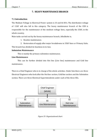
- 1. Chapter 7 Heavy Maintenance NDES (GIT) 51 CEB 7. HEAVY MAINTENANCE BRANCH 7.1 Introduction The Medium Voltage in Electrical Power system is 33 and 66 KVs. The distribution voltage of 11kV will also fall in this category. The heavy maintenance branch of the CEB is responsible for the maintenance of the medium voltage lines, especially the 33kV, in the whole country. Main tasks carried out by the heavy maintenance branch, Athulkotte is; 1. Routine maintenance. 2. Restoration of supply after major breakdowns in 33kV lines or Primary Subs. This branch has divided its functions in to two; Substation Maintenance This is mainly the primary substation maintenance. Line Maintenance This can be further divided into Hot line (Live line) maintenance and Cold line maintenance. There is a Chief Engineer who is in charge of the whole activities. Under him there are three Electrical Engineers who look after the Hot line section, Cold line section and the Substation section. There are three Electrical Superintendents under each of the three EEs. Figure 35- Organizational chart Chief Engineer (MVM) EE Substation Maintenance EE Line Maintenance EE Hot Line Maintenance
- 2. Chapter 7 Heavy Maintenance NDES (GIT) 52 CEB 7.2. Tower Line Maintenance Pole Lines Concrete, wooden, lattice or Tubular type pole. Low in strength. Line direction can change easily. Always use disk & pin insulators. Can be used for short spans (about 60m). Normally use for short lines (few kilometers). Mainly used for final distribution line. Lightning protection is not essential for these lines. Tower Lines Lattice structure. High in strength. Always use Tension & suspension insulators. Self supported or sometimes externally supported Can be used for long span (maximum about 500 m). Suitable for long lines (about 50 km). Changing line direction is limited. Lightning protection is very important & very essential. TYPE OF DISTRIBUTION LINES POLE LINES TOWER LINES
- 3. Chapter 7 Heavy Maintenance NDES (GIT) 53 CEB Identification of Towers Self supported Towers Single Circuit Double Circuit Four Circuit Towers Tower type Mast type TSL TSM TSH TST MSL MSM MSH MST Tower type Mast type MDL MDM MDH MDT TDL TDM TDH TDT First letter - Identify, Tower or Mast Second letter - Identify, single circuit or double circuit Third letter - L – 0 degree, M – 30 degree, H – 60 degree, T – Terminal T4L T4M T4H T4T Single Circuit Double Circuit Double Circuit (Single earth) (Double earth) Figure36-Identification of Towers
- 4. Chapter 7 Heavy Maintenance NDES (GIT) 54 CEB Parts identification of a tower Peak portion Cage part Base height 3950mm 1986mm 1600mm 1882mm 1882mm 1600mm 10m
- 5. Chapter 7 Heavy Maintenance NDES (GIT) 55 CEB Suspension tower (DC Lynx Line) Tension tower (DC Lynx Line) Figure37- Suspension &Tension Tower 7.3. Hot Line Maintenance Hot Line Maintenance includes routine inspection and maintenance in 33kV tower lines all over the country. The purpose of the hot line maintenance is to carry out the operations without the power being cutoff. This promotes the reliability and the stability of the system. The main functions of the hot line maintenance are Inspection and replacement of suspension and pin insulators of the 33kV towers Replacement of cross arms on poles To do above functions specially trained sets of people (Gangs) are needed. There are three gangs and each gang has eight workers. The workers are working with the live 33KV wires. If there is a small mistake, it will cause damages to their lives. So the safety precautions shown below are extremely needed. Always use safety belts and helmets. Use the appropriate tools Do maintenance in suitable weather conditions Always keep the required clearance with the live wire.
- 6. Chapter 7 Heavy Maintenance NDES (GIT) 56 CEB 7.4. Primary Sub Stations Bus Bar Isolator swatch Voltage Transformer 33KV/110V O.C.B. 33KV Current Transformer 100:1 Lighting Arrestor 33KV/11KV Transformer Voltage Transformer 11KV/110V Current Transformer V.C.B. 11KV C.T. V.C.B. C.T. V.C.B. V.C.B. Figure38- Singleline diagramofa primarysubstation
- 7. Chapter 7 Heavy Maintenance NDES (GIT) 57 CEB Several types substation such as Grid substation, primary substation, satellite substation etc are authorized by the CEB in Transmission and Distribution network. Normally Primary Substation converts 33kV to 11kV. Also a primary substation is fed by one or more 33kV overhead lines and using step down power transformers the substation feeds out three to eight 11kV feeders to distributing points. There are Indoor and Outdoor types Primary substations and outdoor primary substation has outdoor switchyard. Fig.4.C shows single line diagram of a primary substation. In outdoor type substation the High Voltage (HV) side equipments, which are incorporate with 33kV lines, are installed outside including the power transformer. The Low Voltage (LV) equipments are all 11kV type switchgears and they are installed inside a building. The indoor type substation has both HV and LV equipments installed within building but only power transformers are placed outside. The switchgears are operated within sealed chambers filled with pressurized SF6 gas and insulation medium for indoor substation is SF6. 7.5. Power Transformer Generally Primary substation has two transformers running in parallel for contingency reasons. Also these transformers are step down transformers convert voltage from 33kV to 11kV and the rated power of transformers used in primary substations is 5MVA or 10MVA.The vector groups of these are “Dyn11” which means the HT side is connected in delta and LT side is connected in star and the star point is solidly earthed at the substation. The transformers installed at primary substations work with on-load tap changer (OLTC) or off-load tap changer units. The necessity of a tap changer unit is to keep the secondary voltage (11kV) at a constant in situations where there are undesirable changes in primary (33kV) voltage.
- 8. Chapter 7 Heavy Maintenance NDES (GIT) 58 CEB Figure 39- Power transformer details 1. Magnetic oil level indicator main tank 2. Magnetic oil level indicator OLTC 3. Buchholz relay 4. Gas sampling device 5. Top oil temp. Indicator 6. Winding temp. indicator 7. Winding temp indicator LV side 8. Dehydrating breather 9. Conservator main tank 10. 11. OLTC 12. Protective relay for OLTC 13. Pressure relief device main tank 14. Radiator 15, 16, 17. Thermometer pockets 22. Drain and filling valve conservator man tank 23. Drain and filling valve conservator of OLTC 24. Shut off valve conservator main tank 25. Shut off valve conservator of OLTC
- 9. Chapter 7 Heavy Maintenance NDES (GIT) 59 CEB 7.6. Protection of Transformers The most expensive and important equipment in a primary substation is the power transformer therefore a major importance is given to its protection. In the first line of protection there are Lightning arrestors located just before the high voltage terminals of the transformer, these arrestors divert any surges that are headed for the transformer from the 33kV line side. The principle relays and systems used for transformer protection are; Bucholz Device: Providing protection against all kinds of incipient i.e. slow developing faults such as nsulation failure of windings, core heating, fall of oil level due to leaky joints etc. Earth fault relay (Providing protection against earth-faults only.) Over current relay (providing protection mainly against phase to phase faults and overloading.) Differential system (providing protection against both earth and phase faults.) The complete protection of transformer usually requires the combination of above systems. Buchholz Relay Tap to collect gas Oil level Mercury switch Alarm buchholz oil to conservator from conservator Mercury switch Figure 40- Buchholz relay This is the protective device devised to give alarm signal against low oil level, entrance of air through leaking glands, and such other faults which result in evolution of gases due to decomposition of the insulating materials. Two floats are provided in each relay. One is connected to the instantaneous trip circuit for operation in an emergency and the other to the alarm signal only. The Buchholz relay is fitted on the pipe connecting the conservator to the main tank. Buchholz relay are used for transformers of rating 500kVA and above.
- 10. Chapter 7 Heavy Maintenance NDES (GIT) 60 CEB 7.7. Circuit Breakers During the operation of power system, it is often desirable and necessary to switch on and off the various parts (Transmission & distribution) under both normal and abnormal conditions. The arrangement of switches along with fuses cannot serve the desired function of the switchgear in such high capacity circuits. Therefore circuit breakers are used for this purpose. A circuit breaker can make or break a circuit either manually or automatically under all conditions (No load, Full load, and short circuit) Types of circuit breakers: Oil circuit breakers - Employ insulating oil for arc extinction Air blast circuit breakers - High pressure air blast is used for extinguishing the arc SF6 circuit breakers - SF6 gas is used for arc extinction Vacuum circuit breakers - vacuum is used for arc extinction SF6 Circuit Breakers The most used gas circuit breakers are SF6 gas circuit breaker. In such breakers, sulfur hexafluoride (SF6) gas is used as the arc-quenching medium. The SF6 is an electro negative gas and has a strong tendency to absorb free electron. The contacts of the breaker are opened in a high-pressure flow of sf6 gas and an arc is stuck between them. The SF6 circuit breakers have been found to be very effective for high power and high voltage service. Oil circuit breaker The arrangement permits two advantages firstly the current breaking chamber requires a small volume of oil which is just enough for arc excitation secondly, the amount of oil to be replaced as the in the supporting chamber does not get contaminated the arc. The single phase oil circuit breaker, there are only one moving contact.
- 11. Chapter 7 Heavy Maintenance NDES (GIT) 61 CEB Figure 41- oil circuit breaker 7.8. Surge Arrestors High voltage surges are caused in electrical system due to lightning, switching operation and other disturbances. These surges can result in flashovers over line insulators and insulation puncture, resulting in line outages and damages to equipments unless dissipated to ground with the help of the surge arresters. The arresters are designed to offer low resistance to surges at the same time blocking the power frequency current. 7.9 Isolators These are used in a bay in addition to a breaker to confirm the isolation of any equipment by observation, since the on/off positions of a breaker cannot be visualized. This
- 12. Chapter 7 Heavy Maintenance NDES (GIT) 62 CEB can not be operated when the particular line is loaded. There is an inter lock system between circuit breaker and isolator to ensure operators safety. Isolator can only be closed when the particular line circuit breaker is in ‘off’ position and before isolator open, particular line circuit breaker must be closed. Manufacturers of isolator give its nominal current, nominal voltage, insulation level, etc. Figure 42- Surge Arrestors Figure 43 – Isolators 7.10. Auto Re closures Auto re closers are self contaminated devises that make and break the distribution system under normal at and fault conditions. A basic feature of a re closer is to re close immediately once the circuit under which it served breaks due to temporary fault. Re closer will lock out its operation whenever it senses a permanent fault clears before lock out, re closer will reset for another cycle of operation. Before CEB has introduced auto re closers to the distribution system, only DDLO’s are provided as the protective devices. But this needs some one to operate the DDLO in order to isolate the line from the power supply. Therefore by introducing auto re closers to distribution system, the speed of fault clearing has improved and hence which promotes the stability of the power system. Because of these reasons the concepts of auto re closers entered as a time and money saving method [the interruption period becomes less]. The minimum requirement for installing an auto re closer is 100 km 1 MVA. The re closers are sensitive for over current, earth fault and in modern type’s sensitive earth faults too.
- 13. Chapter 7 Heavy Maintenance NDES (GIT) 63 CEB There are three types of auto re closers available in medium voltage system in CEB. SF6 gas auto re closer Oil auto re closer Vacuum auto re closer Figure44- Auto Recloser. 7.11. Drop down Lift off (DDLO) These are commonly used in the CEB distribution network mainly for the protection of distribution transformers and some cases for sectionalizing MV lines. A DDLO is shown by follows picture. Figure45- DDLO switch