SlideShare ist ein Scribd-Unternehmen logo
1 von 33
Residential Housing “Trekanten”, Kristiansand Norway.
Bachelors project – Arch. Tech. and Construction Management
Introduction Conceptual update Design Development Technical Design
Project basis
Project objectives:
• Creation of climate-friendly apartments within financial range for first time
buyers aiding young people in becoming homeowners rather than tenants.
• Development of a worn-out and unused industrial area occupying valuable
space.
Project Thesis
News article#1 News article#2
CD DD TD
Selected planning phases
Project Thesis
Study work plan
Introduction Conceptual update Design Development Technical Design
Dissertation report
Cross laminated timber representing the modern
format of solid timber construction, came as a result of
sawmills overproduction of low-grade wood and the
industry’s ambition to pose a solution for wood in
multi-storey structures.
(Falk, 2005)
• System fundamentals
• Material physics
• Economic aspect
• Environmental aspect
Assembly of single-family dwelling, Sogn og Fjordane - Norway 2015
Introduction Conceptual update Design Development Technical Design
Procurement strategy and organisation
Design Responsibility matrix
Project Organisation- and Interdependencies
Contractual Agreements-and Correspondence
Contract for consulting
services
Client
Kristiansand
Eiendom (public)
Main contractor
AB 92
Sub-contractor Sub-contractor
Architect
OS3 ArchitectsA/S
Client advisor
ABR 89
ICT
External scrutinizer
ABR 89
ICT
Engineer
Multidisciplina ry
engineering A/S
ABR 89
ICT
ABR 89
ICT
Tender act
Tender act
AB 92 AB 92
Maincontracting
Power of attorney
1 2 3 4 5 6 7 8 9 10 11 12 13 14 15 16 17 18 19 20
Paymentplan
Envrionmental programme
Tender Procedure
Conceptual update
Phase specific areas of focus:
1. Brief introduction to the proposed project.
2. Preliminary estimation of project budget, duration and operation costs.
Project Location and site utilisation
Project Location Plan Site Plan
Gross Building Area Plot utilisation
Unit typologies (A-C)
Floor plans
Floor plans (-1/5)
Elevations and sections Perspectives and shadow studies
Elevations
Sections
Perspectives
Shadow studies
Introduction Conceptual update Design Development Technical Design
1 2 3 4 5 6 7 8 9 10 11 12 13 14 15 16 17 18 19 20
Materials selection
Elevation – Materials selection
Introduction Conceptual update Design Development Technical Design
Preliminary budget- and planning
Preliminary master-timeframe
Preliminary time- and cost-estimate
• Preliminary project budget: 42,881.826 kr.
Construction costs: 32,999.861 kr.
Soft costs: 9,881.965 kr.
• Preliminary total project duration:
Design- and planning: XXX.XXX (%)
Construction: XXX.XXX (%)
• Life cycle costs (30 years):
Operation cost per. year: 2,003.224 kr.
Operation cost per. 30 year: 60,096.709 kr.
Preliminary life-cycle costing (LCC)
71%
29%
Estimated Life cycle cost :
Investment cost Operation 30 years
Design Development
Phase specific areas of focus:
1. Structural composition and function in relation to loads and
materials
2. Analysis of fire safety and required passive measurements
3. Analysis of sound performance requirements
4. Planning of installations in regards to space requirements and
routing options
5. Scrutiny of building components in relation to requirements
6. Scrutiny of junctions between adjacent components
7. Elemental cost estimation and planning development
Project scrutiny
- A working tool for project
development
Introduction Conceptual update Design Development Technical Design
1 2 3 4 5 6 7 8 9 10 11 12 13 14 15 16 17 18 19 20
Structural analysis – Vertícal loads Structural analysis – Horisontal loads
Dim. Diagrams
Preliminary dimensioning of structural components
Dim. Hollow-core Dim. Concrete beams
Load summaries
Provision of loads- and design criteria's for proceeding phases
A1. – Project basis Design sectioning
1.1 Structural system
Introduction Conceptual update Design Development Technical Design
1 2 3 4 5 6 7 8 9 10 11 12 13 14 15 16 17 18 19 20
Introduction Conceptual update Design Development Technical Design
1 2 3 4 5 6 7 8 9 10 11 12 13 14 15 16 17 18 19 20
Maximum CLT master plate: 2,95 x 13,8 m
13,8 m
2,95m
≥2,95m
Wall height exceeding 2,95 m
2,40 - 2,95
m
2,40 - 2,95
m
2,40 - 2,95
m
2,40 - 2,95
m
2,40 - 2,95
m
Panels must be laid down during
transportation and flipped to upright
position from truck during assembly.
Flipping of panels may be hazardous in
regards to shear loading of lifting screws.
Requires more individual lifts and time in
regards to jointing.
Wall height not exceeding 2,95 m
≤2,95m
Transport limitations:
Height: 3,0 m
Width: 2,40 m
Length: 13,5 m
Panels can be transported vertically and
requires no flipping during assembly.
Using wall panel of ex. 2,95 m will result in
reduced waste and work-flows in the factory
and on site.
CLT standard size table
1.1 Structural system
0.0
50.0
100.0
150.0
200.0
250.0
300.0
350.0
1.0 2.0 3.0 4.0 5.0 6.0 7.0 8.0 9.0 10.0 11.0 12.0 13.0 14.0 15.0 16.0
Dimension(mm)
Span (m)
Structural slab analysis - Span to thickness ratio
(Vibration limit governing CLT)
Concrete PX-slab CLT - Slab Brettstapel
0.0
50.0
100.0
150.0
200.0
250.0
300.0
350.0
1.0 2.0 3.0 4.0 5.0 6.0 7.0 8.0 9.0 10.0 11.0 12.0
Dimension(mm)
Height (m)
Structural wall analysis - Height to thickness ratio
Concrete Exler (class 6) CLT Wall
Introduction Conceptual update Design Development Technical Design
1 2 3 4 5 6 7 8 9 10 11 12 13 14 15 16 17 18 19 20
Dead load: 1,0 kN/m2 + self-weight Live load: 1,5 kN/m2 Dead load: 16,0 kN/m Live load: 4,5 kN/m
CLT slabs used in functions such as floor slabs exposed to live
loads, are in terms of span length primarily limited by vibration
criteria's which are difficult to satisfy in span lengths ≥ 6 – 6,5 m.
depending upon the load.
In functions where not exposed to live load, the SLS + ULS
criteria's can be met in spans up an approximate 8,0 m.
Dissertatation report
- Chap. 2 - Fundamentals
1.1 Structural system
1.2 Structural connection details
Introduction Conceptual update Design Development Technical Design
1 2 3 4 5 6 7 8 9 10 11 12 13 14 15 16 17 18 19 20
Connection detail A –
CLT slab/ CLT ext. wall
Connection detail B –
CLT wall/Concrete Wall
Connection detail E –
CLT slab/CLT slab
Connection detail D –
CLT int. wall/CLT slab
Connection detail C –
CLT wall panels
2.1 Analysis of fire safety and passive measurements
2.2.1 Analysis of passive measurements (component classification) 2.2.2 Analysis of fire safety
Introduction Conceptual update Design Development Technical Design
1 2 3 4 5 6 7 8 9 10 11 12 13 14 15 16 17 18 19 20
Means of escape – Ground floor Means of escape – First-second floor
Means of escape – Third floor
Component classification – Transverse
Component classification – Longitudinal
Introduction Conceptual update Design Development Technical Design
1 2 3 4 5 6 7 8 9 10 11 12 13 14 15 16 17 18 19 20
2. Analysis of sound performance requirements
On the basis of experiences gained in solid
timber project such as Limnologen,
Sweden 2009, the acoustic climate
showed to be challenged by sound waves
under the normal frames of frequency.
Provided the issues with light-buildings
and transfer of sound, the building must
fulfil sound class B which is added the
spectral correlation Rw C 50-3150.
Dissertatation report
- Chap. 3. - Acoustics
Sintef Byggforsk
- Rapport 80
References
3.1 Planning of installations
2.2.1 Ventilation systems – residential
Introduction Conceptual update Design Development Technical Design
1 2 3 4 5 6 7 8 9 10 11 12 13 14 15 16 17 18 19 20
2.2.1 Sprinkling systems – residential
Type A Type B Type C
Level - complete Scrutiny of residential
Sprinkling systems
Type A Type B Type C
Scrutiny of residential
ventilation systems
Dimensioning of ducts
5. Scrutiny of building components in regards to requirements
Introduction Conceptual update Design Development Technical Design
1 2 3 4 5 6 7 8 9 10 11 12 13 14 15 16 17 18 19 20
Introduction Conceptual update Design Development Technical Design
1 2 3 4 5 6 7 8 9 10 11 12 13 14 15 16 17 18 19 20
5. Scrutiny of building components in regards to requirements
5. Scrutiny of building components in regards to
requirements
Primary exterior wall
Performance requirements and component scrutiny
DocumentationAestctic inspiration
List of requirements Sketch proposals Property analysis
U-value TEKNOS fire
impregnation.
Documentation
Introduction Conceptual update Design Development Technical Design
1 2 3 4 5 6 7 8 9 10 11 12 13 14 15 16 17 18 19 20
Vandkanten, Stavanger – AART .
Sintef - 84
5. Scrutiny of building components in regards to
requirements
Primary floor slab
Performance requirements and component scrutiny
References
List of requirements Sketch proposals Property analysis
Sintef Byggforsk
- Rapport 80
Introduction Conceptual update Design Development Technical Design
1 2 3 4 5 6 7 8 9 10 11 12 13 14 15 16 17 18 19 20
Documentation
Structural
calculation slab
REI 60
classification
Brekke & Strand
- Premis rapport
Structural utilisation slab (6m):
ULS:85% ULS-FIRE: 65% SLS:68%
Performance requirements and component scrutiny
References
List of requirements Sketch proposal Property analysis
Fleretasjerstrehus
- kap. 5
Introduction Conceptual update Design Development Technical Design
1 2 3 4 5 6 7 8 9 10 11 12 13 14 15 16 17 18 19 20
Documentation
Fire design table REI 60
classification
Brekke & Strand
- Premis rapport
5. Scrutiny of building components in regards to
requirements
Unit partition wall
Architectural detail: A Adjacent building parts
Architectural detail: B Adjacent building parts
5. Scrutiny of junctions between adjacent
components
Introduction Conceptual update Design Development Technical Design
1 2 3 4 5 6 7 8 9 10 11 12 13 14 15 16 17 18 19 20
5. Scrutiny of junctions between adjacent
components
Introduction Conceptual update Design Development Technical Design
1 2 3 4 5 6 7 8 9 10 11 12 13 14 15 16 17 18 19 20
Architectural detail: E
Adjacent building parts
Architectural detail: D
Adjacent building parts
Calculation CLT unit costs
5. Elemental cost estimation and planning development
5.1 Elemental cost estimation
Digital quanity extracts
Elemental cost plan
- Sigma estiamtes (sig.)
Elemental cost plan
- report
Estimated project budget at design stage: 41,140.297 kr.
Deviation to preliminary estimate: 1,741.529 (4%)
5.2 Planning development
Master time frame - updated
Level based division of
resources
WBS based division of
resources
Construction time plan (.mpp)
A113 specifications
Estimated construction duration at design stage: 230 days
Total project duration: XXXXXXX days
Deviation to preliminary estimate: XXX.XXX days (33%)
Introduction Conceptual update Design Development Technical Design
1 2 3 4 5 6 7 8 9 10 11 12 13 14 15 16 17 18 19 20
Model: 3L+4L+5
5. Phase specific drawing sets
Floor plans (0-3)
5.1 Plans
5.3 Sections
5.2 Elevations
Unit typologies (A-C)
5.4 Details – standard constructions
Introduction Conceptual update Design Development Technical Design
1 2 3 4 5 6 7 8 9 10 11 12 13 14 15 16 17 18 19 20
Exterior walls
Interior walls
Roofs
Slabs and ceilings
Technical Design
Phase specific areas of focus:
1. Reviewing of building part interfaces
2. Preparation of phase drawings and documentation
3. Carbon management
Introduction Conceptual update Design Development Technical Design
1 2 3 4 5 6 7 8 9 10 11 12 13 14 15 16 17 18 19 20
Introduction Conceptual update Design Development Technical Design
1 2 3 4 5 6 7 8 9 10 11 12 13 14 15 16 17 18 19 20
1- Reviewing of building part interfaces
Architectural detail: A
Review basis – Design Development
Reviewed – Technical Design
Introduction Conceptual update Design Development Technical Design
1 2 3 4 5 6 7 8 9 10 11 12 13 14 15 16 17 18 19 20
1- Reviewing of building part interfaces
Architectural detail: B
Review basis – Design Development
Reviewed – Technical Design
Introduction Conceptual update Design Development Technical Design
1 2 3 4 5 6 7 8 9 10 11 12 13 14 15 16 17 18 19 20
1- Reviewing of building part interfaces
Architectural detail: C
Review basis – Design Development
Reviewed – Technical Design
Introduction Conceptual update Design Development Technical Design
1 2 3 4 5 6 7 8 9 10 11 12 13 14 15 16 17 18 19 20
1- Reviewing of building part interfaces
Architectural detail: C
Review basis – Design Development
Reviewed – Technical Design
Introduction Conceptual update Design Development Technical Design
1 2 3 4 5 6 7 8 9 10 11 12 13 14 15 16 17 18 19 20
Basement
Ground floor
First – second floor
Third floor
Roof level
5. Preparation of drawings for authoritties
5.1 Detailed plans - Arcictectural 5.1 Elevations
5.1 Sections
Typologies (A-C)
5.3 Fire safety
Fire safety – Ground floor
Fire safety – First – second floor
Fire safety – Third floor
Introduction Conceptual update Design Development Technical Design
1 2 3 4 5 6 7 8 9 10 11 12 13 14 15 16 17 18 19 20
Slabs above basement
Slabs above ground floor Slabs above first/second floor
Roof level
5. Preparation of drawings for authoritties
5.1 Detailed plans - Structural 5.2 Ventilation systems
Connection detail A Connection detail B
Type A Type B
Type C Building plan
Dimensioning of ducts
5. Preparation of documentation
Application for
building permit
Calculated Energy
Frame - Incl. U-values
Defined line-losses
- DS 418
Calculation of shadows
5.1 Energy frame
5.2 Administration
5.3 Structural and fire documentation
Introduction Conceptual update Design Development Technical Design
1 2 3 4 5 6 7 8 9 10 11 12 13 14 15 16 17 18 19 20
CLT floor slabs CLT party walls CLT exterior walls
Project specification Fire documentation
(partial)
Plot utilisation
5. Project cost and time management
5.1 Elemental cost and project budget update
Elemental cost plan
- Sigma estiamtes (sig.)
Elemental cost plan
- report
Estimated project budget at design stage: XXX.XXX
Deviation to preliminary estimate (CD): XXX.XXX (33%)
Deviation to elemental cost (DD): XXX.XXX (33%)
5.2 Planning development
Master time frame - updated Construction time plan (.mpp)
Estimated construction duration at design stage: 230 days
Total project duration: XXXXXXX days
Deviation to preliminary estimate: XXX.XXX days (33%)
Deviation to prior phase (DD): XXXXXX days (33%)
Introduction Conceptual update Design Development Technical Design
4 5 6 7 8 9 10 11 12 13 14 15 16 17 18 19 20
Introduction Conceptual update Design Development Technical Design
4 5 6 7 8 9 10 11 12 13 14 15 16 17 18 19 201 2 3
39.55 156.94 49.11 181.52
0% 10% 20% 30% 40% 50% 60% 70% 80% 90% 100%
Sections EC - (t/C02)
Total EC for primary structure - wood as a non CO2 neutral material
EC - 427 t/CO2
Stairwells Basement Roof Main structure
39.55 156.94 0.004.48
0% 10% 20% 30% 40% 50% 60% 70% 80% 90% 100%
Sections EC - (t/C02)
Total EC for primary structure - wood as CO2 neutral material
EC - 196,4 t/CO2
Stairwells Basement Roof Main structure
39.55 156.94 0.00 247.55
0% 10% 20% 30% 40% 50% 60% 70% 80% 90% 100%
Sections EC - (t/C02)
Total EC for primary structure - CLT replaced with pre-fab concrete
EC - 444 t/CO2
Stairwells Basement Roof Main structure
5. Carbon management – Primary super structure
Data set – Wood as non C02 neutral
Data set – Wood as C02 neutral
Data set – CLT replaced with concrete

Weitere ähnliche Inhalte

Was ist angesagt?

EY4106/WT5912 week11
EY4106/WT5912 week11EY4106/WT5912 week11
EY4106/WT5912 week11JOE LYSTER
 
Building performance analysis system IES VE main features overview
Building performance analysis system IES VE main features overviewBuilding performance analysis system IES VE main features overview
Building performance analysis system IES VE main features overviewStatybos Akademija
 
Modelling Natural Ventilation in IES-VE: Case studies & Research Outlook
Modelling Natural Ventilation in IES-VE: Case studies & Research OutlookModelling Natural Ventilation in IES-VE: Case studies & Research Outlook
Modelling Natural Ventilation in IES-VE: Case studies & Research OutlookDaniel Coakley
 
Manoogian Task 5 Final Report
Manoogian Task 5 Final ReportManoogian Task 5 Final Report
Manoogian Task 5 Final ReportBader Alghunaim
 
CEE598_Gummaraj_Bharath_Final_Project
CEE598_Gummaraj_Bharath_Final_ProjectCEE598_Gummaraj_Bharath_Final_Project
CEE598_Gummaraj_Bharath_Final_ProjectBharath Gummaraj
 

Was ist angesagt? (7)

EY4106/WT5912 week11
EY4106/WT5912 week11EY4106/WT5912 week11
EY4106/WT5912 week11
 
Building performance analysis system IES VE main features overview
Building performance analysis system IES VE main features overviewBuilding performance analysis system IES VE main features overview
Building performance analysis system IES VE main features overview
 
Modelling Natural Ventilation in IES-VE: Case studies & Research Outlook
Modelling Natural Ventilation in IES-VE: Case studies & Research OutlookModelling Natural Ventilation in IES-VE: Case studies & Research Outlook
Modelling Natural Ventilation in IES-VE: Case studies & Research Outlook
 
Manoogian Task 5 Final Report
Manoogian Task 5 Final ReportManoogian Task 5 Final Report
Manoogian Task 5 Final Report
 
CEE598_Gummaraj_Bharath_Final_Project
CEE598_Gummaraj_Bharath_Final_ProjectCEE598_Gummaraj_Bharath_Final_Project
CEE598_Gummaraj_Bharath_Final_Project
 
Bip2199sample
Bip2199sampleBip2199sample
Bip2199sample
 
BS09_0104_111
BS09_0104_111BS09_0104_111
BS09_0104_111
 

Ähnlich wie Presentation

IES Faculty - IESVE as a Design Application & Part L Clinic
IES Faculty - IESVE as a Design Application & Part L ClinicIES Faculty - IESVE as a Design Application & Part L Clinic
IES Faculty - IESVE as a Design Application & Part L ClinicIES VE
 
Taming The Wind with Engineered Tall Walls
Taming The Wind with Engineered Tall WallsTaming The Wind with Engineered Tall Walls
Taming The Wind with Engineered Tall Wallsdonaldsimon
 
Economic Concrete Frame Elements to Eurocode 2
Economic Concrete Frame Elements to Eurocode 2Economic Concrete Frame Elements to Eurocode 2
Economic Concrete Frame Elements to Eurocode 2Yusuf Yıldız
 
Ash Townes. AMEC. 27th January
Ash Townes. AMEC. 27th JanuaryAsh Townes. AMEC. 27th January
Ash Townes. AMEC. 27th JanuaryUKTI2014
 
Optimal design solutions of road bridges considering embedded environmental i...
Optimal design solutions of road bridges considering embedded environmental i...Optimal design solutions of road bridges considering embedded environmental i...
Optimal design solutions of road bridges considering embedded environmental i...Svenska Betongföreningen
 
David Pedder_Curriculum Vitae
David Pedder_Curriculum VitaeDavid Pedder_Curriculum Vitae
David Pedder_Curriculum VitaeDavid Pedder
 
Reinforced concrete Course assignments, 2018
Reinforced concrete Course assignments, 2018Reinforced concrete Course assignments, 2018
Reinforced concrete Course assignments, 2018JanneHanka
 
D1 (A1) Erica Pereira Carneiro - Potential improvements in the life-cycle per...
D1 (A1) Erica Pereira Carneiro - Potential improvements in the life-cycle per...D1 (A1) Erica Pereira Carneiro - Potential improvements in the life-cycle per...
D1 (A1) Erica Pereira Carneiro - Potential improvements in the life-cycle per...Svenska Betongföreningen
 
Team 2 mep presentation
Team 2  mep presentationTeam 2  mep presentation
Team 2 mep presentationCampus
 
B tech individual report
B tech individual reportB tech individual report
B tech individual reportong93
 
International Journal of Engineering Research and Development
International Journal of Engineering Research and DevelopmentInternational Journal of Engineering Research and Development
International Journal of Engineering Research and DevelopmentIJERD Editor
 
Construction maintenance
Construction maintenanceConstruction maintenance
Construction maintenanceDeepsonJohn1
 
P.e.b. mini project report
P.e.b. mini project reportP.e.b. mini project report
P.e.b. mini project reportShubham Parab
 
Modern fastening systems in tunnel construction
Modern fastening systems in tunnel constructionModern fastening systems in tunnel construction
Modern fastening systems in tunnel constructionStefan Lammert
 
Modified Risk Analysis Model APRAM
Modified Risk Analysis Model APRAMModified Risk Analysis Model APRAM
Modified Risk Analysis Model APRAMnadeemovic
 

Ähnlich wie Presentation (20)

IES Faculty - IESVE as a Design Application & Part L Clinic
IES Faculty - IESVE as a Design Application & Part L ClinicIES Faculty - IESVE as a Design Application & Part L Clinic
IES Faculty - IESVE as a Design Application & Part L Clinic
 
Taming The Wind with Engineered Tall Walls
Taming The Wind with Engineered Tall WallsTaming The Wind with Engineered Tall Walls
Taming The Wind with Engineered Tall Walls
 
Economic Concrete Frame Elements to Eurocode 2
Economic Concrete Frame Elements to Eurocode 2Economic Concrete Frame Elements to Eurocode 2
Economic Concrete Frame Elements to Eurocode 2
 
Ash Townes. AMEC. 27th January
Ash Townes. AMEC. 27th JanuaryAsh Townes. AMEC. 27th January
Ash Townes. AMEC. 27th January
 
Optimal design solutions of road bridges considering embedded environmental i...
Optimal design solutions of road bridges considering embedded environmental i...Optimal design solutions of road bridges considering embedded environmental i...
Optimal design solutions of road bridges considering embedded environmental i...
 
Simon Bainbridge
Simon BainbridgeSimon Bainbridge
Simon Bainbridge
 
David Pedder_Curriculum Vitae
David Pedder_Curriculum VitaeDavid Pedder_Curriculum Vitae
David Pedder_Curriculum Vitae
 
Reinforced concrete Course assignments, 2018
Reinforced concrete Course assignments, 2018Reinforced concrete Course assignments, 2018
Reinforced concrete Course assignments, 2018
 
D1 (A1) Erica Pereira Carneiro - Potential improvements in the life-cycle per...
D1 (A1) Erica Pereira Carneiro - Potential improvements in the life-cycle per...D1 (A1) Erica Pereira Carneiro - Potential improvements in the life-cycle per...
D1 (A1) Erica Pereira Carneiro - Potential improvements in the life-cycle per...
 
Team 2 mep presentation
Team 2  mep presentationTeam 2  mep presentation
Team 2 mep presentation
 
B tech individual report
B tech individual reportB tech individual report
B tech individual report
 
International Journal of Engineering Research and Development
International Journal of Engineering Research and DevelopmentInternational Journal of Engineering Research and Development
International Journal of Engineering Research and Development
 
Construction maintenance
Construction maintenanceConstruction maintenance
Construction maintenance
 
P.e.b. mini project report
P.e.b. mini project reportP.e.b. mini project report
P.e.b. mini project report
 
Modern fastening systems in tunnel construction
Modern fastening systems in tunnel constructionModern fastening systems in tunnel construction
Modern fastening systems in tunnel construction
 
Integrative Design Working With Your Mep
Integrative Design Working With Your MepIntegrative Design Working With Your Mep
Integrative Design Working With Your Mep
 
Modified Risk Analysis Model APRAM
Modified Risk Analysis Model APRAMModified Risk Analysis Model APRAM
Modified Risk Analysis Model APRAM
 
AMIF2014 – [Nautica] Andreas Echtermeyer, Compositi in applicazioni navali e ...
AMIF2014 – [Nautica] Andreas Echtermeyer, Compositi in applicazioni navali e ...AMIF2014 – [Nautica] Andreas Echtermeyer, Compositi in applicazioni navali e ...
AMIF2014 – [Nautica] Andreas Echtermeyer, Compositi in applicazioni navali e ...
 
DML CV 17
DML CV 17DML CV 17
DML CV 17
 
Presentation 2016
Presentation  2016Presentation  2016
Presentation 2016
 

Presentation

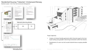
  • 1. Residential Housing “Trekanten”, Kristiansand Norway. Bachelors project – Arch. Tech. and Construction Management Introduction Conceptual update Design Development Technical Design Project basis Project objectives: • Creation of climate-friendly apartments within financial range for first time buyers aiding young people in becoming homeowners rather than tenants. • Development of a worn-out and unused industrial area occupying valuable space. Project Thesis News article#1 News article#2 CD DD TD Selected planning phases Project Thesis Study work plan
  • 2. Introduction Conceptual update Design Development Technical Design Dissertation report Cross laminated timber representing the modern format of solid timber construction, came as a result of sawmills overproduction of low-grade wood and the industry’s ambition to pose a solution for wood in multi-storey structures. (Falk, 2005) • System fundamentals • Material physics • Economic aspect • Environmental aspect Assembly of single-family dwelling, Sogn og Fjordane - Norway 2015
  • 3. Introduction Conceptual update Design Development Technical Design Procurement strategy and organisation Design Responsibility matrix Project Organisation- and Interdependencies Contractual Agreements-and Correspondence Contract for consulting services Client Kristiansand Eiendom (public) Main contractor AB 92 Sub-contractor Sub-contractor Architect OS3 ArchitectsA/S Client advisor ABR 89 ICT External scrutinizer ABR 89 ICT Engineer Multidisciplina ry engineering A/S ABR 89 ICT ABR 89 ICT Tender act Tender act AB 92 AB 92 Maincontracting Power of attorney 1 2 3 4 5 6 7 8 9 10 11 12 13 14 15 16 17 18 19 20 Paymentplan Envrionmental programme Tender Procedure
  • 4. Conceptual update Phase specific areas of focus: 1. Brief introduction to the proposed project. 2. Preliminary estimation of project budget, duration and operation costs.
  • 5. Project Location and site utilisation Project Location Plan Site Plan Gross Building Area Plot utilisation Unit typologies (A-C) Floor plans Floor plans (-1/5) Elevations and sections Perspectives and shadow studies Elevations Sections Perspectives Shadow studies Introduction Conceptual update Design Development Technical Design 1 2 3 4 5 6 7 8 9 10 11 12 13 14 15 16 17 18 19 20 Materials selection Elevation – Materials selection
  • 6. Introduction Conceptual update Design Development Technical Design Preliminary budget- and planning Preliminary master-timeframe Preliminary time- and cost-estimate • Preliminary project budget: 42,881.826 kr. Construction costs: 32,999.861 kr. Soft costs: 9,881.965 kr. • Preliminary total project duration: Design- and planning: XXX.XXX (%) Construction: XXX.XXX (%) • Life cycle costs (30 years): Operation cost per. year: 2,003.224 kr. Operation cost per. 30 year: 60,096.709 kr. Preliminary life-cycle costing (LCC) 71% 29% Estimated Life cycle cost : Investment cost Operation 30 years
  • 7. Design Development Phase specific areas of focus: 1. Structural composition and function in relation to loads and materials 2. Analysis of fire safety and required passive measurements 3. Analysis of sound performance requirements 4. Planning of installations in regards to space requirements and routing options 5. Scrutiny of building components in relation to requirements 6. Scrutiny of junctions between adjacent components 7. Elemental cost estimation and planning development Project scrutiny - A working tool for project development Introduction Conceptual update Design Development Technical Design 1 2 3 4 5 6 7 8 9 10 11 12 13 14 15 16 17 18 19 20
  • 8. Structural analysis – Vertícal loads Structural analysis – Horisontal loads Dim. Diagrams Preliminary dimensioning of structural components Dim. Hollow-core Dim. Concrete beams Load summaries Provision of loads- and design criteria's for proceeding phases A1. – Project basis Design sectioning 1.1 Structural system Introduction Conceptual update Design Development Technical Design 1 2 3 4 5 6 7 8 9 10 11 12 13 14 15 16 17 18 19 20
  • 9. Introduction Conceptual update Design Development Technical Design 1 2 3 4 5 6 7 8 9 10 11 12 13 14 15 16 17 18 19 20 Maximum CLT master plate: 2,95 x 13,8 m 13,8 m 2,95m ≥2,95m Wall height exceeding 2,95 m 2,40 - 2,95 m 2,40 - 2,95 m 2,40 - 2,95 m 2,40 - 2,95 m 2,40 - 2,95 m Panels must be laid down during transportation and flipped to upright position from truck during assembly. Flipping of panels may be hazardous in regards to shear loading of lifting screws. Requires more individual lifts and time in regards to jointing. Wall height not exceeding 2,95 m ≤2,95m Transport limitations: Height: 3,0 m Width: 2,40 m Length: 13,5 m Panels can be transported vertically and requires no flipping during assembly. Using wall panel of ex. 2,95 m will result in reduced waste and work-flows in the factory and on site. CLT standard size table 1.1 Structural system
  • 10. 0.0 50.0 100.0 150.0 200.0 250.0 300.0 350.0 1.0 2.0 3.0 4.0 5.0 6.0 7.0 8.0 9.0 10.0 11.0 12.0 13.0 14.0 15.0 16.0 Dimension(mm) Span (m) Structural slab analysis - Span to thickness ratio (Vibration limit governing CLT) Concrete PX-slab CLT - Slab Brettstapel 0.0 50.0 100.0 150.0 200.0 250.0 300.0 350.0 1.0 2.0 3.0 4.0 5.0 6.0 7.0 8.0 9.0 10.0 11.0 12.0 Dimension(mm) Height (m) Structural wall analysis - Height to thickness ratio Concrete Exler (class 6) CLT Wall Introduction Conceptual update Design Development Technical Design 1 2 3 4 5 6 7 8 9 10 11 12 13 14 15 16 17 18 19 20 Dead load: 1,0 kN/m2 + self-weight Live load: 1,5 kN/m2 Dead load: 16,0 kN/m Live load: 4,5 kN/m CLT slabs used in functions such as floor slabs exposed to live loads, are in terms of span length primarily limited by vibration criteria's which are difficult to satisfy in span lengths ≥ 6 – 6,5 m. depending upon the load. In functions where not exposed to live load, the SLS + ULS criteria's can be met in spans up an approximate 8,0 m. Dissertatation report - Chap. 2 - Fundamentals 1.1 Structural system
  • 11. 1.2 Structural connection details Introduction Conceptual update Design Development Technical Design 1 2 3 4 5 6 7 8 9 10 11 12 13 14 15 16 17 18 19 20 Connection detail A – CLT slab/ CLT ext. wall Connection detail B – CLT wall/Concrete Wall Connection detail E – CLT slab/CLT slab Connection detail D – CLT int. wall/CLT slab Connection detail C – CLT wall panels
  • 12. 2.1 Analysis of fire safety and passive measurements 2.2.1 Analysis of passive measurements (component classification) 2.2.2 Analysis of fire safety Introduction Conceptual update Design Development Technical Design 1 2 3 4 5 6 7 8 9 10 11 12 13 14 15 16 17 18 19 20 Means of escape – Ground floor Means of escape – First-second floor Means of escape – Third floor Component classification – Transverse Component classification – Longitudinal
  • 13. Introduction Conceptual update Design Development Technical Design 1 2 3 4 5 6 7 8 9 10 11 12 13 14 15 16 17 18 19 20 2. Analysis of sound performance requirements On the basis of experiences gained in solid timber project such as Limnologen, Sweden 2009, the acoustic climate showed to be challenged by sound waves under the normal frames of frequency. Provided the issues with light-buildings and transfer of sound, the building must fulfil sound class B which is added the spectral correlation Rw C 50-3150. Dissertatation report - Chap. 3. - Acoustics Sintef Byggforsk - Rapport 80 References
  • 14. 3.1 Planning of installations 2.2.1 Ventilation systems – residential Introduction Conceptual update Design Development Technical Design 1 2 3 4 5 6 7 8 9 10 11 12 13 14 15 16 17 18 19 20 2.2.1 Sprinkling systems – residential Type A Type B Type C Level - complete Scrutiny of residential Sprinkling systems Type A Type B Type C Scrutiny of residential ventilation systems Dimensioning of ducts
  • 15. 5. Scrutiny of building components in regards to requirements Introduction Conceptual update Design Development Technical Design 1 2 3 4 5 6 7 8 9 10 11 12 13 14 15 16 17 18 19 20
  • 16. Introduction Conceptual update Design Development Technical Design 1 2 3 4 5 6 7 8 9 10 11 12 13 14 15 16 17 18 19 20 5. Scrutiny of building components in regards to requirements
  • 17. 5. Scrutiny of building components in regards to requirements Primary exterior wall Performance requirements and component scrutiny DocumentationAestctic inspiration List of requirements Sketch proposals Property analysis U-value TEKNOS fire impregnation. Documentation Introduction Conceptual update Design Development Technical Design 1 2 3 4 5 6 7 8 9 10 11 12 13 14 15 16 17 18 19 20 Vandkanten, Stavanger – AART . Sintef - 84
  • 18. 5. Scrutiny of building components in regards to requirements Primary floor slab Performance requirements and component scrutiny References List of requirements Sketch proposals Property analysis Sintef Byggforsk - Rapport 80 Introduction Conceptual update Design Development Technical Design 1 2 3 4 5 6 7 8 9 10 11 12 13 14 15 16 17 18 19 20 Documentation Structural calculation slab REI 60 classification Brekke & Strand - Premis rapport Structural utilisation slab (6m): ULS:85% ULS-FIRE: 65% SLS:68%
  • 19. Performance requirements and component scrutiny References List of requirements Sketch proposal Property analysis Fleretasjerstrehus - kap. 5 Introduction Conceptual update Design Development Technical Design 1 2 3 4 5 6 7 8 9 10 11 12 13 14 15 16 17 18 19 20 Documentation Fire design table REI 60 classification Brekke & Strand - Premis rapport 5. Scrutiny of building components in regards to requirements Unit partition wall
  • 20. Architectural detail: A Adjacent building parts Architectural detail: B Adjacent building parts 5. Scrutiny of junctions between adjacent components Introduction Conceptual update Design Development Technical Design 1 2 3 4 5 6 7 8 9 10 11 12 13 14 15 16 17 18 19 20
  • 21. 5. Scrutiny of junctions between adjacent components Introduction Conceptual update Design Development Technical Design 1 2 3 4 5 6 7 8 9 10 11 12 13 14 15 16 17 18 19 20 Architectural detail: E Adjacent building parts Architectural detail: D Adjacent building parts
  • 22. Calculation CLT unit costs 5. Elemental cost estimation and planning development 5.1 Elemental cost estimation Digital quanity extracts Elemental cost plan - Sigma estiamtes (sig.) Elemental cost plan - report Estimated project budget at design stage: 41,140.297 kr. Deviation to preliminary estimate: 1,741.529 (4%) 5.2 Planning development Master time frame - updated Level based division of resources WBS based division of resources Construction time plan (.mpp) A113 specifications Estimated construction duration at design stage: 230 days Total project duration: XXXXXXX days Deviation to preliminary estimate: XXX.XXX days (33%) Introduction Conceptual update Design Development Technical Design 1 2 3 4 5 6 7 8 9 10 11 12 13 14 15 16 17 18 19 20 Model: 3L+4L+5
  • 23. 5. Phase specific drawing sets Floor plans (0-3) 5.1 Plans 5.3 Sections 5.2 Elevations Unit typologies (A-C) 5.4 Details – standard constructions Introduction Conceptual update Design Development Technical Design 1 2 3 4 5 6 7 8 9 10 11 12 13 14 15 16 17 18 19 20 Exterior walls Interior walls Roofs Slabs and ceilings
  • 24. Technical Design Phase specific areas of focus: 1. Reviewing of building part interfaces 2. Preparation of phase drawings and documentation 3. Carbon management Introduction Conceptual update Design Development Technical Design 1 2 3 4 5 6 7 8 9 10 11 12 13 14 15 16 17 18 19 20
  • 25. Introduction Conceptual update Design Development Technical Design 1 2 3 4 5 6 7 8 9 10 11 12 13 14 15 16 17 18 19 20 1- Reviewing of building part interfaces Architectural detail: A Review basis – Design Development Reviewed – Technical Design
  • 26. Introduction Conceptual update Design Development Technical Design 1 2 3 4 5 6 7 8 9 10 11 12 13 14 15 16 17 18 19 20 1- Reviewing of building part interfaces Architectural detail: B Review basis – Design Development Reviewed – Technical Design
  • 27. Introduction Conceptual update Design Development Technical Design 1 2 3 4 5 6 7 8 9 10 11 12 13 14 15 16 17 18 19 20 1- Reviewing of building part interfaces Architectural detail: C Review basis – Design Development Reviewed – Technical Design
  • 28. Introduction Conceptual update Design Development Technical Design 1 2 3 4 5 6 7 8 9 10 11 12 13 14 15 16 17 18 19 20 1- Reviewing of building part interfaces Architectural detail: C Review basis – Design Development Reviewed – Technical Design
  • 29. Introduction Conceptual update Design Development Technical Design 1 2 3 4 5 6 7 8 9 10 11 12 13 14 15 16 17 18 19 20 Basement Ground floor First – second floor Third floor Roof level 5. Preparation of drawings for authoritties 5.1 Detailed plans - Arcictectural 5.1 Elevations 5.1 Sections Typologies (A-C) 5.3 Fire safety Fire safety – Ground floor Fire safety – First – second floor Fire safety – Third floor
  • 30. Introduction Conceptual update Design Development Technical Design 1 2 3 4 5 6 7 8 9 10 11 12 13 14 15 16 17 18 19 20 Slabs above basement Slabs above ground floor Slabs above first/second floor Roof level 5. Preparation of drawings for authoritties 5.1 Detailed plans - Structural 5.2 Ventilation systems Connection detail A Connection detail B Type A Type B Type C Building plan Dimensioning of ducts
  • 31. 5. Preparation of documentation Application for building permit Calculated Energy Frame - Incl. U-values Defined line-losses - DS 418 Calculation of shadows 5.1 Energy frame 5.2 Administration 5.3 Structural and fire documentation Introduction Conceptual update Design Development Technical Design 1 2 3 4 5 6 7 8 9 10 11 12 13 14 15 16 17 18 19 20 CLT floor slabs CLT party walls CLT exterior walls Project specification Fire documentation (partial) Plot utilisation
  • 32. 5. Project cost and time management 5.1 Elemental cost and project budget update Elemental cost plan - Sigma estiamtes (sig.) Elemental cost plan - report Estimated project budget at design stage: XXX.XXX Deviation to preliminary estimate (CD): XXX.XXX (33%) Deviation to elemental cost (DD): XXX.XXX (33%) 5.2 Planning development Master time frame - updated Construction time plan (.mpp) Estimated construction duration at design stage: 230 days Total project duration: XXXXXXX days Deviation to preliminary estimate: XXX.XXX days (33%) Deviation to prior phase (DD): XXXXXX days (33%)
  • 33. Introduction Conceptual update Design Development Technical Design 4 5 6 7 8 9 10 11 12 13 14 15 16 17 18 19 20 Introduction Conceptual update Design Development Technical Design 4 5 6 7 8 9 10 11 12 13 14 15 16 17 18 19 201 2 3 39.55 156.94 49.11 181.52 0% 10% 20% 30% 40% 50% 60% 70% 80% 90% 100% Sections EC - (t/C02) Total EC for primary structure - wood as a non CO2 neutral material EC - 427 t/CO2 Stairwells Basement Roof Main structure 39.55 156.94 0.004.48 0% 10% 20% 30% 40% 50% 60% 70% 80% 90% 100% Sections EC - (t/C02) Total EC for primary structure - wood as CO2 neutral material EC - 196,4 t/CO2 Stairwells Basement Roof Main structure 39.55 156.94 0.00 247.55 0% 10% 20% 30% 40% 50% 60% 70% 80% 90% 100% Sections EC - (t/C02) Total EC for primary structure - CLT replaced with pre-fab concrete EC - 444 t/CO2 Stairwells Basement Roof Main structure 5. Carbon management – Primary super structure Data set – Wood as non C02 neutral Data set – Wood as C02 neutral Data set – CLT replaced with concrete