NAT (network address translation) & PAT (port address translation)
•
3 gefällt mir•1,945 views

NAT (Network Address Translation) allows private IP networks to connect to the Internet by translating private IP addresses to public IP addresses. It operates on a router, connecting internal and external networks. NAT provides security by hiding internal network addresses and conserving IP addresses. There are various NAT types, including static NAT for one-to-one address mapping, dynamic NAT for mapping private addresses to public addresses from a pool, and NAT overload/PAT for mapping multiple private addresses to a single public address using ports.

Empfohlen
Weitere ähnliche Inhalte
Was ist angesagt?
Was ist angesagt? (20)
Ähnlich wie NAT (network address translation) & PAT (port address translation)
Ähnlich wie NAT (network address translation) & PAT (port address translation) (20)
Mehr von Netwax Lab
Mehr von Netwax Lab (20)
Kürzlich hochgeladen
Kürzlich hochgeladen (20)
NAT (network address translation) & PAT (port address translation)
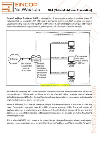
- 1. NAT (Network Address Translation) Network Address Translation (NAT) is designed for IP address conservation. It enables private IP networks that use unregistered IP addresses to connect to the Internet. NAT operates on a router, usually connecting two networks together, and translates the private (not globally unique) addresses in the internal network into legal addresses, before packets are forwarded to another network. As part of this capability, NAT can be configured to advertise only one address for the entire network to the outside world. This provides additional security by effectively hiding the entire internal network behind that address. NAT offers the dual functions of security and address conservation and is typically implemented in remote-access environments. When IP addressing first came out, everyone thought that there were plenty of addresses to cover any need. Theoretically, you could have 4,294,967,296 unique addresses (232). The actual number of available addresses is smaller (somewhere between 3.2 and 3.3 billion) because of the way that the addresses are separated into classes, and because some addresses are set aside for multicasting, testing or other special uses. This is where NAT (RFC 1631) comes to the rescue. Network Address Translation allows a single device, such as a router, to act as an agent between the Internet (or "public network") and a local (or "private") Figure 1 NAT (Network Address Translation)
- 2. NAT (Network Address Translation) network. This means that only a single, unique IP address is required to represent an entire group of computers. But the shortage of IP addresses is only one reason to use NAT. Cisco's version of NAT lets an administrator create tables that map: A local IP address to one global IP address statically, A local IP address to any of a rotating pool of global IP addresses that a company may have, A local IP address plus a particular TCP port to a global IP address or one in a pool of them, A global IP address to any of a pool of local IP addresses on a round-robin basis. Developed by Cisco, Network Address Translation is used by a device (firewall, router or computer that sits between an internal network and the rest of the world. NAT has many forms and can work in several ways: 1. Static NAT- Mapping an unregistered IP address to a registered IP address on a one-to-one basis. Particularly useful when a device needs to be accessible from outside the network. 2. Dynamic NAT- Maps an unregistered IP address to a registered IP address from a group of registered IP addresses. 3. NAT Overload or PAT- A form of dynamic NAT that maps multiple unregistered IP addresses to a single registered IP address by using different ports. This is known also as PAT (Port Address Translation), single address NAT or port-level multiplexed NAT. 4. Overlapping- When the IP addresses used on your internal network are registered IP addresses in use on another network, the router must maintain a lookup table of these addresses so that it can intercept them and replace them with registered unique IP addresses. It is important to note that the NAT router must translate the "internal" addresses to registered unique addresses as well as translate the "external" registered addresses to addresses that are unique to the private network. This can be done either through static NAT or by using DNS and implementing dynamic NAT. The following list describes the different types of addresses: 1. Local: This refers to what happens on the inside of your network. 2. Global: This refers to what happens on the outside of your network. 3. Inside Local Address: This is an address of a host on your internal network, for example, 192.168.8.25.
- 3. NAT (Network Address Translation) 4. Inside Global Address: This is the mapped address that people on the Internet would see, which represents the inside host. 5. Outside Global Address: The IP address of a remote Internet-based host as assigned by the owner that can communicate with an inside host, for example, 192.0.2.100. 6. Outside Local Address: This is the address that the inside hosts use to reference an outside host. The outside local address may be the outside host’s actual address or another translated private address from a different private address block. Therefore, the router could translate that address to 192.168.10.50, or it could be the public address of the external host. The internal hosts would contact this address to deal with the external host. NAT Configuration Basically, NAT allows a single device, such as a router, to act as an agent between the Internet (or public network) and a local network (or private network), which means that only a single unique IP address is required to represent an entire group of computers to anything outside their network. In order to configure traditional NAT, you need to make at least one interface on a router (NAT outside) and another interface on the router (NAT inside) and a set of rules for translating the IP addresses in the packet headers (and payloads if desired) need to be configured. Figure 2 Example Config for Static, Dynamic & Overload NAT
- 4. NAT (Network Address Translation) Here we need to add Double Serial interfaces on each ISPs routers. R1 (config) #int s0/0 R1 (config-if) #ip add 12.1.1.1 255.255.255.0 R1 (config-if) #no shut R1 (config-if) #clock rate 64000 R1 (config-if) #int s0/1 R1 (config-if) #ip add 41.1.1.2 255.255.255.0 R1 (config-if) #no shut R1 (config-if) #clock rate 64000 R1 (config-if) #int s0/2 R1 (config-if) #ip add 101.1.1.1 255.255.255.0 R1 (config-if) #no shut R1 (config-if) #clock rate 64000 Now on R2 R2 (config) #int s0/0 R2 (config-if) #ip add 12.1.1.2 255.255.255.0 R2 (config-if) #no shut R2 (config-if) #int s0/1 R2 (config-if) #ip add 23.1.1.1 255.255.255.0 R2 (config-if) #no shut R2 (config-if) #clock rate 64000 Now on R3 R3 (config) #int s0/0 R3 (config-if) #ip add 23.1.1.2 255.255.255.0 R3 (config-if) #no shut R3 (config-if) #int s0/1 R3 (config-if) #ip add 34.1.1.1 255.255.255.0 R3 (config-if) #no shut R3 (config-if) #clock rate 64000 R3 (config-if) #int s0/2 R3 (config-if) #ip add 201.1.1 255.255.255.0 R3 (config-if) #no shut R3 (config-if) #clock rate 64000 R3 (config-if) #int fa0/0 R3 (config-if) #ip add 40.1.1.1 255.255.255.0 R3 (config-if) #no shut
- 5. NAT (Network Address Translation) Now on R4 R4 (config) #int s0/0 R4 (config-if) #ip add 34.1.1.2 255.255.255.0 R4 (config-if) #no shut R4 (config-if) #int s0/1 R4 (config-if) #ip add 41.1.1.1 255.255.255.0 R4 (config-if) #no shut R4 (config-if) #clock rate 64000 R4 (config-if) #int fa0/0 R4 (config-if) #ip add 30.1.1.1 255.255.255.0 R4 (config-if) #no shut Now on HO Router HO (config) #int s0/0 HO (config-if) #ip add 101.1.1.10 255.255.255.0 HO (config-if) #no shut HO (config-if) #clock rate 64000 HO (config-if) #int fa0/0 HO (config-if) #ip add 192.168.1.1 255.255.255.0 HO (config-if) #no shut Now on BO Router BO (config) #int s0/0 BO (config-if) #ip add 201.1.1.10 255.255.255.0 BO (config-if) #no shut BO (config-if) #clock rate 64000 BO (config-if) #int fa0/0 BO (config-if) #ip add 192.168.1.1 255.255.255.0 BO (config-if) #no shut Now here we will run routing protocol on ISPs router R1 (config) #router ei 100 R1 (config-router) #network 0.0.0.0 R1 (config-router) #no auto-summary R2 (config) #router ei 100 R2 (config-router) #network 0.0.0.0 R2 (config-router) #no auto-summary
- 6. NAT (Network Address Translation) R3 (config) #router ei 100 R3 (config-router) #network 0.0.0.0 R3 (config-router) #no auto-summary R4 (config) #router ei 100 R4 (config-router) #network 0.0.0.0 R4 (config-router) #no auto-summary Now we will provide the IP address to the Server Server 1 30.1.1.2 Server 2 40.1.1.2 Now server will ping all four routers of ISPs. R1 ping HO router but HO would not ping r2. R1 ping because it’s directly connected with HO router. Now here I will perform default routing on HO router HO (config) #ip route 0.0.0.0 0.0.0.0 101.1.1.1 Now HO would be able to ping all the ISPs router and server. Now I will perform default routing on BO also BO (config) #ip route 0.0.0.0 0.0.0.0 201.1.1.1 Now BO would also be able to ping all the ISPs routers and server. BO would also be able to ping HO Router. Now we will give the IP to BOs PC 192.168.1.2 192.168.1.3 192.168.1.4 Here we will provide the IP to HOs PC 192.168.1.2 192.168.1.3 192.168.1.4 What we can see here is we can’t pint ISPs router through HOs Host. Because private IP add doesn’t work over the internet. It would not ping either server.
- 7. NAT (Network Address Translation) Now suppose we purchased three Public IP of the same range 101.1.1.2 101.1.1.3 101.1.1.4 Here we will perform Static NATting HO (config) #int s0/0 HO (config-if) #ip nat outside HO (config-if) #int fa0/0 HO (config-if) #ip nat inside HO (config-if) #exit HO (config) #ip nat inside source static 192.168.1.2 101.1.1.2 HO (config) #ip nat inside source static 192.168.1.3 101.1.1.3 HO (config) #ip nat inside source static 192.168.1.4 101.1.1.4 Now HOs PC would be able to ping ISPs router and server also. HO#sh ip nat translation HO#sh ip nat statistics Now here we will perform static routing on BO routers Suppose we purchased these public IP addresses. 201.1.1.2 201.1.1.3 201.1.1.4 BO (config) #int fa0/0 BO (config-if) #ip nat inside BO (config-if) #int s0/0 BO (config-if) #ip nat outside BO (config-if) #exit BO (config) #ip nat inside source static 192.168.1.2 201.1.1.2 BO (config) #ip nat inside source static 192.168.1.3 201.1.1.3 BO (config) #ip nat inside source static 192.168.1.4 201.1.1.4 BO #sh ip nat translation Now here BO would ping ISPs router and server. Now on HO we will connect three more PCs. 192.168.1.5 192.168.1.6
- 8. NAT (Network Address Translation) 192.168.1.7 But the new PC would not ping their server. Now we will create here Dynamic NATting On HO we need to remove static NAT first. HO (config) #no ip nat inside source static 192.168.1.2 101.1.1.2 HO (config) #no ip nat inside source static 192.168.1.3 101.1.1.3 HO (config) #no ip nat inside source static 192.168.1.4 101.1.1.4 In Dynamic NAT First come First Serve would work. HO (config) #access-list 10 permit 192.168.1.0 0.0.0.255 HO (config) #int fa0/0 HO (config-if) #ip nat inside HO (config-if) #int s0/0 HO (config-if) #ip nat outside HO (config-if) #exit HO (config) #ip nat pool HR ? HO (config) #ip nat pool 101.1.1.2 101.1.1.4 netmask 255.255.255.0 HO (config) #ip nat inside source list 10 pool HR Now From HO all the PC would ping the ISP and server. HO#sh ip nat translation HO #clear ip nat translation HO#sh ip nat translation Now here we will remove Dynamic NAT HO (config) #ip nat pool HR 101.1.1.2 101.1.1.4 netmask 255.255.255.0 HO (config) #no ip nat inside source list 10 pool HR HO (config) #no access-list 10 Now here we will perform NAT Overload/PAT HO (config) #int s0/0 HO (config-if) #ip nat outside HO (config-if) #int fa0/0 HO (config-if) #ip nat inside HO (config) #access-list 10 permit 192.168.1.0 0.0.0.255 HO (config) #ip nat inside source list 10 int s0/0 overload
- 9. NAT (Network Address Translation) Now HOs all the PC will ping ISPs router and server. HO#sh ip nat translation HO #Clear Ip nat translation Overlapping Let’s talk through what we are going to do here. We want R1 to be able to hit R4′s loopback and vice- verse, but we need to trick both routers in a way. If R1 just tries to ping 100.0.0.4 nothing is going to go down because R1 has a directly connected route for 100.0.0.0/24. If R4 tries to ping 100.0.0.1 it will have the same issue. We will use NAT in both directions to solve this problem. In other words, R1 has to believe it is talking to some other IP address other than 100.0.0.4 and R4 has to believe it is talking to something other than 100.0.0.1. Before we do that, let’s setup some basic default routing on R1 and R4. R1(config)#ip route 0.0.0.0 0.0.0.0 12.12.12.2 R4(config)#ip route 0.0.0.0 0.0.0.0 24.24.24.2 let’s setup our NAT on R2 R1(config)#interface FastEthernet0/0.12 R1(config-if)# ip nat inside R1(config)#interface FastEthernet0/0.24 R1(config-if)#ip nat outside R1(config)#ip nat inside source static 100.0.0.1 11.11.11.11 R1(config)#ip nat outside source static 100.0.0.4 44.44.44.44 Let’s break down what the packet flow is going to look like here. When R1 sources a ping packet from 100.0.0.1 destined to 44.44.44.44 two things will happen. Our inside NAT rule there will translate the source of the packet to 11.11.11.11. At the same time, the outside NAT rule will translate the destination of the packet to 100.0.0.4 If everything gets routed OK, R4 will receive an ICMP echo packet sourced from 11.11.11.11 and destined to 100.0.0.4 and it will send an ICMP echo reply sourced from 100.0.0.4 and destined to 11.11.11.11. When R2 receives the packet, it will then translate the source of the packet to 44.44.44.44 and translate the destination of the packet to 100.0.0.1 at the same time The thing to keep in mind is that both the inside and outside NAT rules work bidirectionally. In other words, when I say ip nat inside source static 100.0.0.1 11.11.11.11 I am actually telling the router to do Figure 3 Example Config for Overlapping NAT
- 10. NAT (Network Address Translation) two things. If the packet is sourced from 100.0.0.1 on the inside interface, translate the source to 11.11.11.11. Also, if the packet is destined to 11.11.11.11 on the outside interface, translate the destination to 100.0.0.1. The outside NAT rule is similar in accomplishing two things. When I say ip nat outside source static 100.0.0.4 44.44.44.44 I am telling the router to do two things. If the packet is sourced from 100.0.0.4 and coming in the outside interface, translate the source to 44.44.44.44. When packets come in the inside interface destined to 44.44.44.44, translate the destination to 100.0.0.4.