General Monitors Flame Detectors Scp
•Als PPS, PDF herunterladen•
2 gefällt mir•2,001 views

The document provides information on the operation, maintenance and specifications of the SCP Flame Detectors Model FL3110. It discusses the principles of UV/IR flame detection, specifications including field of view and optical sensitivity range, visual indicators, wiring details, general maintenance including lens cleaning, and use of the TL105 test lamp for checking detector sensitivity.

Empfohlen
Weitere ähnliche Inhalte
Was ist angesagt?
Was ist angesagt? (20)
Ähnlich wie General Monitors Flame Detectors Scp
Ähnlich wie General Monitors Flame Detectors Scp (20)
Kürzlich hochgeladen
Kürzlich hochgeladen (20)
General Monitors Flame Detectors Scp
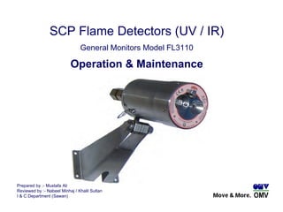
- 1. Prepared by :- Mustafa Ali Reviewed by :- Nabeel Minhaj / Khalil Sultan I & C Department (Sawan) SCP Flame Detectors (UV / IR) General Monitors Model FL3110 Operation & Maintenance
- 2. Principle of Operation. The Model FL3110 is a discriminating UV/IR Detector, which makes use of an ultraviolet radiation sensitive phototube in addition to an infrared detector. This combination provides a flame detection system, which is highly immune to false alarms. Since a flame is a copious source of both ultraviolet and infrared radiation, discrimination is provided when both UV and IR emissions are detected. If only UV is detected, as in the case of arc welding, no alarm is given. If only IR is detected, such as a large modulating hot object, no alarm is given. However, if both conditions are met in the correct combination and intensity, as determined by an algorithm in the microcomputer, a fire is identified and the alarm outputs are activated.
- 3. IR Detector centre wavelength: 4.35 microns UV Detector Pass Band: 185 to 260 nanometres Supply voltage range: 20 to 36 VDC Load @ 24 VDC: 600 Ohms Output Relay Contact Ratings: 1A MAX @ 30VRMS/42.2 VPK, Resistive. RFI/EMI Protection Complies with EN50270, Type 2 Status Indicator: Two LEDs indicate status, fault conditions. Approvals: ATEX & CE Mark Operating temperature range: -40°C to 90°C -40°F to 194°F Specifications.
- 4. Detector Field of View. Each Model FL3110 and FL3111 Flame Detector have a maximum cone of vision of 120º. This Cone has its vertex at the center of the detector. Optical Sensitivity Range. The distance at which the detector will respond to a flame is a function of the intensity of that flame. The maximum distance is 50 feet (15.2m) for a gasoline fire with a surface area of 1 square foot (0.92m2).
- 5. Optical Path Monitoring ( COPM ) checks the optical path, related electronic circuitry once every minute. If foreign material impairs the optical path of the UV detector tube & infrared detector for two consecutive checks, the unit will indicate FAULT. The optical FAULT outputs de-energizing of the FAULT relay. After a COPM FAULT, a COPM check is performed every ten seconds until the obstruction is removed. Then the COPM check will resume checking once per minute check. Self-testing feature. Resetting the Flame Detector. All versions may be reset by interrupting the power supply for a minimum of two seconds.
- 6. Two light emitting diodes ( LEDs ) are visible through the IR window. LEDs are provided for a visual indication that corresponds with the detector’s outputs with the following blinking sequence . Timeout (10 seconds when the unit is first powered) – Green and red LEDs blinking alternately. • Ready – Green LED that flashes off 1 second, every 5 seconds. • WARNING – Slow blinking red LED. • ALARM – Fast blinking red LED. • COPM FAULT – Slow blinking green LED. • Low Voltage FAULT – Fast blinking green LED. Visual Indicators.
- 7. Flame Detector Wiring Details. ( SCP Installation )
- 8. A1 ALM The WARN output is immediate. A2 ALM This connection is the ALARM relay contact. The ALARM output is time delayed for 2, 4, 8 or 10 seconds. FAULT The FAULT output configuration is normally energised and non-latching. The FAULT circuit will be activated during the time-out function, a low power or loss of power condition, and during a failed COPM check. During these conditions the FAULT relay will de-energise duration of the FAULT. COMM This is the common connection of the WARN, ALARM and FAULT relay contacts. Flame Detector Wiring Details. (Relay Output)
- 9. A clean, soft, lint-free cloth, tissue or cotton swab should be used to clean the lenses deflector and light rod. The removal of particulate matter and any film build-up on the lenses, light rod and reflector is necessary to ensure proper sensitivity of the system. It is recommended that the lens and reflector be cleaned at least every 30 days’ or more often if the detector is located in a particularly dirty environment. Warning: A dirty or partially blocked lens can significantly reduce the detector’s field of view and detection distance General Maintenance.
- 10. The TL105 is a battery operated, rechargeable test lamp specifically designed to test General Monitors’ UV/IR Flame Detectors. The test lamp provides a high-energy, broadband radiation source that emits sufficient energy in both the ultraviolet and infrared spectra to activate UV and/or IR flame detectors. To avoid damaging exposure to ultraviolet radiation, the TL105 provides a "Power On" indicator so that direct viewing of the lamp is not necessary. The TL100 is approved by CSA as intrinsically safe for use in Class I, Division 1, Groups C & D. Fire Detector Sensitivity Check. ( Simulation )