Brooks SLA Pressure Controllers Offer Wide Range and Advanced Diagnostics
•
0 gefällt mir•45 views

This document provides information on BrooksInstrument pressure controllers and flowmeters. It discusses that the SLA Series controllers and flowmeters have gained acceptance for accuracy, stability, and reliability. They have a wide pressure measurement and control range, making them suitable for various applications. Key features highlighted include long-term stability, accuracy backed by superior metrology, and a variety of I/O options. The controllers are also available with weatherproof enclosures. The document then discusses the core control technology used, and that the controllers provide a single platform to support various applications through their wide range of options and features.

Empfohlen
Empfohlen
Weitere ähnliche Inhalte
Was ist angesagt?
Was ist angesagt? (20)
Ähnlich wie Brooks SLA Pressure Controllers Offer Wide Range and Advanced Diagnostics
Ähnlich wie Brooks SLA Pressure Controllers Offer Wide Range and Advanced Diagnostics (20)
Kürzlich hochgeladen
Kürzlich hochgeladen (20)
Brooks SLA Pressure Controllers Offer Wide Range and Advanced Diagnostics
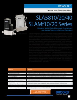
- 1. 1 BrooksInstrument.com The SLA Series pressure controllers and pressure controlling flowmeters have gained broad acceptance as the standard for accuracy, stability and reliability. These products have a wide pressure measurement and control range and are suitable for a broad range of operating conditions making them well suited for applications in thin film processes, chemical and petrochemical research, laboratory, analytical, fuel cell and life science among others. Highlights of the SLA Series pressure controller product include: industry leading long term stability, accuracy backed by superior metrology systems and methods using primary flow calibration systems directly traceable to international standards, and a broad range of analog and digital I/O options to suit virtually any application. An independent diagnostic/ service port permits users to troubleshoot or change process conditions without removing the pressure controller from service. This product is also available with a NEMA 4X/IP66 approved enclosure, making it perfect for hosedown/washdown applications. Based on the core control technology present in our industry-leading thermal mass flow controllers, Brooks’ SLA Pressure Controllers are able to control the pressure of a gas based on a set point signal by replacing the thermal mass flow sensor with a pressure sensor. It utilizes closed-loop control, which eliminates the droop and hysteresis associated with traditional mechanical spring diaphragm pressure regulators. With the wide range of options and features available, the SLA Pressure Controller Series provides users with a single platform to support a broad range of applications. DATA SHEET Pressure Mass Flow Controllers SLAMf10/20 Series Elastomer Sealed, Digital, Upstream, Downstream, and RemoteTransducer Pressure Controllers Model SLA5810/20/40 Model SLAMf10/20 Closed loop control Eliminates droop & hysteresis associated with traditional mechanical spring diaphragm pressure regulators User accessible service port Simplified installation, start-up, troubleshooting and access to diagnostics provides maximum uptime Wide pressure range capabilities Ability to control up to 4500 psig, giving it one of the widest pressure ranges on the market today Advanced diagnostics Ensures device is operating within user specified limits for high process yield and maximum uptime Superior valve technology Minimum leak-by, maximum turndown, fast response reduces overall gas panel cost and increases throughput Easily retrofit to existing systems Primary standard calibration systems Ensures measurement accuracy is traceable to international standards Simple modular design Easy-to-service elastomer sealed design provides options for factory or field service maximizing uptime and reducing total cost of ownership IP66/NEMA 4X rated enclosure Weatherproof protection optional for “Hosedown” applications such as: Food, Beverage, Pharmaceutical & Biotech Hazardous area approvals Designed to operate in non-incendive (Division 2/Zone 2) environments SLA5810/20/40 Features Benefits View SLA5810/20/40 SLAMf10/20 Product Page
- 2. 2 Product Description Flexible Pressure Control Capabilities Brooks’ Pressure Controllers can be built for both upstream pressure control and downstream pressure control. These designations are determined by the location of the vessel where the pressure is being controlled. Our upstream pressure controllers can also be considered back pressure regulators, and our downstream pressure controllers can also be considered pressure regulators. In addition, a remote transducer configuration can be used to combine the benefits of pressure control and flow measurement. Advanced Diagnostics Pressure Controllers can be some of the most complex components in a gas delivery system, but they are typically critical to the tool’s success. When dealing with highly toxic or corrosive gases, removing the pressure controller to determine if it is faulty should be the last resort. In response to this, Brooks pioneered smarter products with embedded self test routines and introduced an independent diagnostic/service port and software to provide the user with a simple interface, for troubleshooting without disturbing pressure controller operation. Wide Pressure Range The SLA Pressure Controller Series covers an extremely broad range of pressures. Brooks Pressure Controllers can control pressures ranging from sub-atmosphere all the way to 4500 psi (310 bar), giving it the widest pressure range on the market today! Even with major changes to the flowrate, Brooks Pressure Controllers are able to maintain stable pressure which keeps processes running smoothly and efficiently. Broad Array of Communication Options Brooks offers traditional analog options as well as RS-485 digital communications (“S-protocol”, based on HART) Brooks also offers control interfaces via digital network protocols like DeviceNet (DeviceNet not available on SLAMf 10/20), a high speed (up to 500k baud) digital communication network, and Profibus. Brooks’ communication capabilities and device-profiles have been certified by the ODVA (Open DeviceNet Vendor’s Association) and the ITK (Interoperability Test Kit). Other network protocols are in development. Talk to your Brooks representative about your specific needs. Wash-down Enclosure The SLAMf Series comes equipped with an IP66 / NEMA4X rated enclosure. This makes these instruments perfect for wash-down or outdoor environments. So no matter how harsh the surroundings, the SLAMf Series keeps the process under control. Hazardous Area Approvals Brooks SLA Pressure Controller products come with various levels of Hazardous Area Approvals. The SLA5800 Series Pressure Controllers are approved for Class I, Division 2/Zone 2 areas, while the SLAMF Series Pressure Controllers have enclosures that can be used in Class II & Class III, Division 2/Zone 2.
- 3. Product Specifications SLA58510/20 & SLAMf10/20 SLA5840 PERFORMANCE MECHANICAL DIAGNOSTICS RATINGS Min. F.S. Max. F.S. Pressure Controller Model Pressure Controller Model Flow Ranges N2 Eq. Ratings Maximum Full Scale Pressure Pressure Equipment Directive (PED) Module H Category Standard Standard Flow Ranges and Pressure Ratings: SLA5810/SLAMf10 Downstream 0.003 50* 1 psi 1500 psia/103 bara Sound Engineering (Pressure Regulator) 0.1 10 1500 psi 4500 psia/310 bara Practices (SEP) SLA5820/SLAMf20 Upstream 0.003 50* 1 psi 1500 psia/103 bara Sound Engineering (Back Pressure Regulator) 0.1 10 1500 psi 4500 psia/310 bara Practices (SEP) SLA5840 Remote Transducer 0.003 50 10 psi 1500 psia/103 bara Sound Engineering Upstream or Downstream 0.1 10 1500 psi 4500 psia/310 bara Practices (SEP) * Please see sizing tool for flow limitations < 10 psi F.S. pressure Minimum Full Scale Pressure Pressure Accuracy +0.25% of Transducer F.S., F.S. > 300 psia Dependent on Remote Pressure Transducer (Including Linearity and Hysteresis) +0.12% of Transducer F.S., F.S. ≤ 300 psia Flow Accuracy (N2 equivalent) N/A ±0.9% of S.P. (20-100% F.S.) +0.18% of F.S. (2-20% F.S., 1-20% F.S. from 1-50 lpm) Control Range 20:1 Typical - Application specific Repeatability & Reproducibility 0.20% S.P. Linearity Included in accuracy Response Time (Settling time within System dependent <1 second ±2% F.S. for 0-100% command step) Zero Stability < + 0.001% F.S. per 30 days Dependent on Remote Pressure Transducer Temperature Coefficient ±0.1% of F.S. per °C Dependent on Remote Pressure Transducer Pressure Coefficient N/A ±0.03% per psi (0-200 psi N2) (Flow Measurement Only) Attitude Sensitivity The accuracy of the Pressure Sensor is not attitude dependent Operating Temperature Range -14 to 65o C (7 to 149o F)** Transducer Pressure Ratings 15 psia/1.03 bara for < 15 psia full scale Dependent on Remote Pressure Transducer 15 psig/1.03 barg for < 15 psig full scale 100 psia/6.9 bara for < 100 psia full scale 100 psig/6.9 barg for 15-100 psig full scale 300 psia/20.7 bara for 100-300 psia full scale 300 psig/20.7 barg for 100-300 psig full scale 3000 psia/206.9 bara for 300-3000 psia full scale 4500 psia/310.3 bara for 3000-4500 psia full scale Leak Integrity (external) 1x10⁻⁹ atm. cc/sec He Valve Type Normally Closed, Normally Open Primary Wetted Materials 316L Stainless Steel, High Alloy Stainless Steel, Viton® fluoroelastomers. Optional Buna-N, Kalrez® , Teflon® /Kalrez® , and EPDM Status Lights MFC Health, Network Status Alarms* Sensor Output, Control Valve Output, Over Temperature, Power Surge/Sag, Network Interruption Diagnostic/Service Port RS485 via 2.5 mm jack (Located under the top cover in SLAMf version) * Alarm modes are dependent on the communications interface. These are described in the corresponding digital communication interface manual. ** Hazardous area certifications have a temperature range limitation of 0-65°C.
- 4. 4 Electrical Specifications VOLTAGE SET POINT INPUT SPECIFICATIONS CURRENT SET POINT INPUT SPECIFICATIONS FLOW OUTPUT (VOLTAGE) SPECIFICATIONS FLOW OUTPUT (CURRENT) SPECIFICATIONS ANALOG I/O ALARM OUTPUT* ANALOG I/O VALVE OVERRIDE SIGNAL SPECIFICATIONS** Product Specifications Communication Protocol RS485 Profibus® DeviceNet® *** Electrical Connection (SLA58xx) 1 x 15-pin Male Sub-D, (A) 1 x 15-pin Male Sub-D 1 M12 with threaded 1 x 9-pin Female Sub-D coupling nut (B) Electrical Connection (SLAMf) PG11 Cable Gland, 1/2” NPT (F) Conduit, M20 x 1.5 Conduit N/A Analog I/O 0-5 V, 1-5 V, 0-10 V, 0-20 mA, 4-20 mA N/A Power Max./Purge From +13.5 Vdc to +27 Vdc From +11 Vdc to +25 Vdc Power Requirements Watts, Max. Valve Orifice > 0.032”: 8.7 Watts Valve Orifice > 0.032”: 10 Watts Valve Orifice ≤ 0.032”: 5.2 Watts Valve Orifice ≤ 0.032”: 7 Watts Nominal Range 0-5 Vdc, 1-5 Vdc or 0-10 Vdc N/A Full Range (-0.5)-11 Vdc N/A Absolute Max. 18 V (without damage) N/A Input Impedence >990 kOhms N/A Nominal Range 4-20 mA or 0-20 mA N/A Full Range 0-22 mA N/A Absolute Max. 24 mA (without damage) N/A Input Impedence 100 Ohms N/A Nominal Range 0-5 Vdc, 1-5 Vdc or 0-10 Vdc N/A Full Range (-1)-11 Vdc N/A Min Load Resistance 2 kOhms N/A Nominal Range 0-20 mA or 4-20 mA N/A Full Range 0-22 mA N/A Max. Load 380 Ohms N/A Type Open Collector N/A Max. Closed (On) Current 25 mA N/A Max. Open (Off) Leakage 1µA N/A Max. Open (Off) Voltage 30 Vdc N/A Floating/Unconnected Instrument controls valve to command set point N/A VOR < 0.3 Vdc Valve Closed N/A 0.3 Vdc < VOR < 4.8 Vdc Undefined N/A VOR > 4.8 Vdc Valve Open N/A Input Impedence 60 kOhms N/A Absolute Max. Input (-25 Vdc) < VOR < 25 Vdc (without damage) N/A *The Alarm Output is an open collector or "contact type" that is CLOSED (on) whenever an alarm is active. The Alarm Output may be set to indicate any one of various alarm conditions. ** The Valve Override Signal (VOR) is implemented as an analog input which measures the voltage at the input and controls the valve based upon the measured reading as shown in this section. *** Available on SLA5810/20/40 only.
- 5. 5 Certifications Certifications - SLA58XX Mark Agency Certification Applicable Standard Details UL (Recogonized) Class I, Div 2, Group A, B, C, D Class I, Zone 2, IIC T4 Class II, Zone 22 UL & CSA Standards E73889 Vol 3, Sec 4 ATEX II 3 G Ex nA IIC T4 Gc EN60079-0:2012 EN 60079-15:2010 KEMA 04ATEX 1118X IECEx II 3 G Ex nA IIC T4 Gc IEC 60079-0:2011 IEC 60079-15:2010 IECEx DEK 14.0072X KOSHA Ex nA IIC T4 15-AV4BO-0641 15-AV4BO-0640 CE EMC Directive 2014/30/EU Directive 2011/65/EU EN:61326-1:2013 EMC RoHS Certifications - SLAMfxx
- 6. 6 Product Dimensions SLA5810/20, Thru-Flow, Profibus SLA5810/20, Thru-Flow, RS485 Note : Aux. Input only used for Remote Transducer Pressure Controllers. Note : Aux. Input only used for Remote Transducer Pressure Controllers.
- 7. 7 Product Dimensions SLA5840, Thru-Flow, Profibus SLA5810/20, Thru-Flow, DeviceNet Note : Aux. Input only used for Remote Transducer Pressure Controllers. Note : Aux. Input only used for Remote Transducer Pressure Controllers.
- 8. 8 Product Dimensions SLA5840, Thru-Flow, DeviceNet SLAMf10/20, Thru-Flow, RS485 Note : Aux. Input only used for Remote Transducer Pressure Controllers. Note : Aux. Input only used for Remote Transducer Pressure Controllers.
- 9. 9 Product Dimensions Access our library of CAD Drawings SLAMf10/20, Thru-Flow, Profibus Note : Aux. Input only used for Remote Transducer Pressure Controllers.
- 10. 10 Model Code I. Base Model Numbers SLA Smart Link Advantage II. Package / Finish Specifications 58 Standard Elastomer Series MF Standard Elastomer Series (NEMA 4X/IP66 Housing) III. Function 1 Downstream Pressure Controller 2 Upstream Pressure Controller 4 Remote Transducer Pressure Controller (SLA58xx only) IV. Gas or Range 0 3 ccm - 50 lpm V. Digital I/O Communication A None (select applicable analog I/O) (SLA58xx Pressure Controllers) D DeviceNet I/O (with 5-pin micro connector) (Only on SLA5810/20/40) P Profibus (2x sub-D) S RS485 (select applicable analog I/O) V. Digital I/O Communication A None (select applicable analog I/O) (SLAMfxx Pressure Controllers) P Profibus (5-pin female M12, M20 x 1.5 conduit) R Profibus (5-pin female M12, PG11 cable gland) T Profibus (5-pin female M12, 1/2” NPT (F) conduit) S RS485 (select applicable analog I/O) VI. Mechanical Connection 1A Without adapters, 9/16” - 18 UNF 1B 1/4” tube compression 1C 1/8” tube compression 1D 3/8” tube compression 1E 1/4” VCR 1F 1/4” VCO 1G 1/4” NPT 1H 6mm tube compression 1J 10mm tube compression 1L 3/8”-1/2” VCR 1M 3/8”-1/2” VCO 1P 1/2” tube compression 1T 1/4” RC (BSP) 1Y 3mm tube compression B1 1/4” tube compression w/filter C1 1/8” tube compression w/filter D1 3/8” tube compression w/filter E1 1/4” VCR w/filter F1 1/4” VCO w/filter G1 1/4” NPT w/filter H1 6mm tube compression w/filter J1 10mm tube compression w/filter L1 3/8”-1/2” VCR w/filter M1 3/8”-1/2” VCO w/filter P1 1/2” tube compression w/filter T1 1/4” RC (BSP) w/filter Y1 3mm tube compression w/filter VII. O-ring Material A Viton B Buna C PTFE D Kalrez E EPDM J FDA/USP Class VI - Viton L FDA/USP Class VI - EPDM VIII. Valve Seat B Viton C Buna D Kalrez E EPDM F PTFE G Metal (SLA5810/20/40 Only) IX. Valve Type 1 Normally closed (≤ 1500 psi) 4 Normally closed High Pressure (1500 - 4500 psi) 5 Normally open (SLA5810/20 Only) (≤ 1500 psi) Code Description Code Option Option Description
- 11. 11 Model Code Code Description Code Option Option Description Request a Quote X. Analog I/O A None - Digital Communications only Communications B 0-5 Volt 0-5 Volt (SLA58xx Pressure Controllers) C 4-20 mA 4-20 mA L 1-5 Volt 1-5 Volt M 0-20 mA 0-20 mA 0 0-10 Volt 0-10 Volt 1 0-5 Volt 4-20 mA 2 0-5 Volt 0-20 mA 3 4-20 mA 0-5 Volt 4 0-20 mA 0-5 Volt 9 0-10 Volt 0-5 Volt X. Analog I/O A None - Digital Communications only Communications E 4-20 mA 0-5 Volt PG11 Gland (SLAMfxx Pressure Controllers) F 0-5 Volt 0-5 Volt PG11 Gland G 4-20 mA 4-20 mA PG11 Gland H 0-5 Volt 4-20 mA PG11 Gland I 0-5 Volt 0-20 mA PG11 Gland J 0-5 Volt 0-5 Volt 1/2” NPT (F) Conduit K 4-20 mA 4-20 mA 1/2” NPT (F) Conduit N 0-5 Volt 4-20 mA M20 x 1.5 Conduit O 0-5 Volt 0-20 mA M20 x 1.5 Conduit P 4-20 mA 0-5 Volt M20 x 1.5 Conduit Q 0-20 mA 0-5 Volt M20 x 1.5 Conduit R 1-5 Volt 1-5 Volt PG11 Gland S 0-20 mA 0-20 mA PG11 Gland T 1-5 Volt 1-5 Volt 1/2” NPT (F) Conduit U 0-20 mA 0-20 mA 1/2” NPT (F) Conduit V 0-5 Volt 0-5 Volt M20 x 1.5 Conduit W 1-5 Volt 1-5 Volt M20 x 1.5 Conduit X 0-20 mA 0-20 mA M20 x 1.5 Conduit Y 4-20 mA 4-20 mA M20 x 1.5 Conduit Z 0-20 mA 0-5 Volt PG11 Gland 5 0-5 Volt 4-20 mA 1/2” NPT (F) Conduit 6 0-5 Volt 0-20 mA 1/2” NPT (F) Conduit 7 4-20 mA 0-5 Volt 1/2” NPT (F) Conduit 8 0-20 mA 0-5 Volt 1/2” NPT (F) Conduit XI. Power Supply Inputs 1 +15 Vdc 2 24 Vdc XII. Output Enhancements A Standard response XIII. Certification 1 Safe Area 2 For Zone II Atex/IECEx Sample Standard Model Code I II III IV V VI VII VIII IX X XI XII XIII SLA 58 5 0 A 1A A B 1 B 1 A 1
- 12. 12 Service and Support Brooks is committed to assuring all of our customers receive the ideal flow solution for their application, along with outstanding ser- vice and support to back it up. We operate first class repair facilities located around the world to provide rapid response and support. Each location utilizes primary standard calibration equipment to ensure accuracy and reliability for repairs and recalibration and is certified by our local Weights and Measures Authorities and traceable to the relevant International Standards. Visit www.BrooksInstrument.com to locate the service location nearest to you. START-UP SERVICE AND IN-SITU CALIBRATION Brooks Instrument can provide start-up service prior to operation when required. For some process applications, where ISO-9001 Quality Certification is important, it is mandatory to verify and/or (re)calibrate the products periodically. In many cases this service can be provided under in-situ conditions, and the results will be traceable to the relevant international quality standards. CUSTOMER SEMINARS AND TRAINING Brooks Instrument can provide customer seminars and dedicated training to engineers, end users, and maintenance persons. Please contact your nearest sales representative for more details. Due to Brooks Instrument’s commitment to continuous improvement of our prod- ucts, all specifications are subject to change without notice. TRADEMARKS Brooks.............................................................. Brooks Instrument, LLC All other trademarks are the property of their respective owners. 2020 DS-PR-SLA5800-SLAMf-Series-RevB-PC-RT-eng/2017-1