KPC/ME 6th Semester/ How to approach a Autocad 2D drawing/Ms.Smriti Bhakat
Vice Grip Soldiworks Project
1. CA
Project G
T
software,
Siemens.
models b
the desire
Pliers to
become f
ability to
feature an
the pliers
report. A
jaws to s
Backgro
V
not lose g
contains
narrow th
grip a wi
release th
jaws.
T
Nose, me
pliers. Th
jaw hand
displayed
AD/CAM: M
Goals
The required
, called NX
. The softwa
behavior. All
ed product. T
be done piec
familiar with
o develop a f
nalysis of a
s will be dem
A small rod m
imulate the p
ound
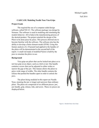
Vise-grips are
grip on an ob
a screw that
he gap of the
ide range of
hat pushed th
The pliers bei
eaning the ja
he pliers are
dle, grip, rele
d below.
Modeling N
the use of a
8.5. The soft
are is used in
l to help in th
The project e
ce by piece.
h the softwar
finite elemen
10 pound lo
monstrated in
made of mod
pliers in use
e pliers that
bject, such a
t can be adju
e jaw. This f
widths. The
he handles a
ing modeled
aw is longer
comprised o
ease, link, an
Needle Nose V
computer ai
ftware packa
n modeling a
he manufact
entailed the
This proces
re. The softw
nt model (FE
ad applied to
n the second
dified Nylon
.
can be locke
as a bolt or n
usted to eithe
feature allow
other handl
apart in order
d in this repo
and narrowe
of six differe
nd screw. Th
Vise-Grips
ided design
age was desig
and simulatin
turing proces
design of th
s allowed on
ware also has
EM). Using t
o the handle
d half of the
is held by th
ed into place
nut. One hand
er widen or
ws the pliers
e contains th
r to unlock th
ort are Needl
er than ordin
ent pieces: ja
hese six piece
gn by
ng the
ss of
he
ne to
s the
this
s of
he
e as to
dle
to
he
he
le
nary
aw,
es are
Figure 1: Needle Nose Vis
Michael La
Fall
se‐Grips
agalle
2014
3.
Figure 7: Screw
All of these parts were modeled using the measurements taken and provided in the
dimensioned sketches of each part. These sketches will be provided in the appendix section of
this report.
Solid Model (CAD)
The following section will contain instructions on how the
solid model was created. The section will broke down into
sections for each part.
a. Jaw
Step 1a:
Start New Model
Create new sketch on xc-yc plane
Use Circle Tools where specified and Fillet command to curve edges
Step 2a: Extrude
Jaw Base:
Symmetric and a distance of .255/2 in
4. Jaw Nose:
Symmetric distance of .2 in
Boolean: Unite
Jaw Teeth:
Straight edge teeth used Symmetric cut through
entire solid.
Curved edge teeth used Pattern Feature along
curve.
Jaw Blade:
Extrude Subtract
Starting Distance: .05 in
Finishing Distance: .35 in
Then feature was mirrored to opposite side with the
Mirror Feature tool.
Both edges were chamfered a distance of .05 in to form
a cutting blade.
6. Step 2b
Extrude Intersect the Jaw feature with Jaw Handle sketch. Symmetric 1 in.
Use Sweep command with connected
curves. Select Cubic and connect by
points in menu.
Extrude subtract the top hole.
Extrude: Boolean: Unite
Starting Distance 0 in
Ending Distance .3 in
Use Insert Thread Feature
8. Step 2c Extrude
Base
Region Bound by Curve
Symmetric 5/16 in
Cut
Symmetric through whole solid
Boolean: Subtract
Then use Mirror Feature to cut other side.
Step 3c Shell
Thickness: 0.07 in
Click Cylinder too clear them.
9. Complete
d. Release
Step 1d
Create Sketch
Begin with guide curve
Use fillet and make sure the curves are tangent
Using the New Datum Command created 7
new datums and place each sketch on its
respective datum.
10. Step 2d
Sweep
Connected Curves
Verify direction of sweep is same for
each sketch
Set to Cubic and Alignment by points
Extrude
Boolean: Subtract
Through whole object
Complete
11. e. Link
Step 1e
Create Sketch
Fillets and Circles for
the curved edges.
Step 2e
Extrude
Symmetric
Distance: 3/32 in
12. Completed
f. Screw
Create 3 cylinders all positioned at
origin.
Use the Unite command to make them
one.
Chamfer the edges.
Insert Feature Threads
Start New Sketch on Screw
Insert polygon.
Extrude
Boolean: Subtract
Starting distance: 0 in
Ending distance: .15 in
13. Completed
Assembly
This section goes through each step of the assembly process using NX 8.5.
Step 1
Start a new assembly. Insert all of the created parts.
Move them using the “Move” command as well as the
dynamic motion. Position them near the points they
are planned to be constrained.
Add constraint “Fix” on to the Jaw Handle.
14. Step 2
Add constraint “Fit” to the Jaw and Jaw handle.
Select the inner cylindrical faces on both parts.
Step 3
Add constraint “Touch Align” to the Jaw and Jaw
Handle. Select the top two faces as highlighted in
the figure to the right.
Step 4
Use the “Fit” constraint on the Grip and Jaw. Select the
inner cylindrical faces of both parts.
15. Step 5
Use the “Center” constraint. Select the two faces of the
jaw, and then the two exterior faces of the grip.
Step 6
Add the “Fit” constraint to the grip and release. Select
the inner cylindrical faces of the holes, as pictured.
Step 7
Add the “Touch Align” constraint.
Replace the reference set of both the grip and release
with the actual part. Use the “Touch Align” constraint on
the xc-yc plane of each part.
Step 8
Add “Angle” constraint.
Keeping both part
reference set to Entire part.
Select the xc-zc plane of
the release, then the xc-zc
plane of the grip. Set the
angle to a value of 150°.
16. Step 9
Use “Fit” constraint.
Select the inner cylindrical faces on the holes of both
the grip and link.
Step 10
Use “Center” constraint.
Select the two faces of the link, and the inner two
faces of the grip.
Step 11
Use “Touch Align” constraint.
Orientation: Infer Center/Axis
Select the Center/Axis of screw and slot on
the bottom of the handle.
Step 12
Use “Distance” Constraint
Select bottom face of screw head and bottom face of
handle.
Set value to 0.2 in
17. Step 13
Use “Touch Align” constraint.
Select inner face of link and the left side of
the lower edge on screw.
Step 14
Use “Touch Align” constraint
Select the bottom face of link and the right
side of the top edge of screw.
20. Part Drafting
Summary
Nx was fairly successful in the modeling of the parts and assembly. The errors found
while putting assembly together were mostly due to human error, in either the measurement of
the physical parts or through improper dimension of the models. Even with the human error, the
finished product does provide a sufficient model for the actual pliers, and they closely resemble
each other.
21. Overview
T
solid mod
combinat
Analysis
calculatio
1. O
2. P
3. M
st
w
The following
del. Through
tion of vario
will display
ons of the sta
Open Assemb
romote Enti
Midsurface b
trategy Prog
Finite Ele
g section wil
h the use of
ous elements
y the resultin
atic analysis
bly. Start Ne
re part.
by Face Pair
ressive. Clic
ment Mode
ll cover the p
1-D, 2-D, an
to simulate
ng forces in t
s will also be
ew FEM. An
s for grip, li
ck automatic
el (FEM) &
process that
nd 3-D mesh
connections
the connectio
e displayed.
nd SIM. Go t
ink and jaw
cally Create F
Simulation
was used fin
hes. As well
s. All connec
ons, displace
to Idealized
handle. Sele
Face Pairs.
(SIM)
nite element
as the use of
ctions were c
ements, and
part.
ect the spec
t model from
f gluing and
checked.
stresses. Ha
ified bodies
m the
d a
and
. Use
22. 4. Split body. Highlight entire model. Tool: New Plane. Set to the ZC plane.
5. Divide Face:
a. First Insert “Curve from Bodies” – “Intersect”. First set will be the half
midsurface face of the jaw handle. The second set will be the faces of the jaw.
b. Use Divide Face Command:
i. Select face of Handle.
ii. Selected the newly generated curves.
23. 6. Merge Faces: Grip
7. 2D Mesh:
a. Type: CQUAD4
b. Size: 0.05 in
c. All in Separate Collectors
24. 8. 3D Mesh:
a. Type: CTETRA(4)
b. Size: 0.05 in
c. Separate collectors
9. 2D Extruded Mesh: Screw Hole on Jaw Handle
a. Insert – Element – Extrude
i. Type: Element Edges
ii. Number of copies: 6
iii. Distance: 0.05 in
iv. Along Direction of Screw
25. 10. R
11. M
Connect
Screw an
Ball Join
Create 3
Add a RB
Create a
Create a
Then cre
they node
Reflect Mesh
a. Hide L
b. Insert
i.
ii.
Merge Nodes
a. Select
b. Set To
tions
nd Handle
nt Connection
Nodes and c
BE2 Elemen
4th node on
CBUSH on
ate a CBUSH
es on the edg
h:
Link
– Element –
Select Ent
Specify Pl
s
t entire mode
olerance: 0.0
n
connect them
nt on Middle
the node clo
the coincide
H on the nod
ge of the link
– Copy and R
tire part, exc
lane: ZC plan
el
01 in
m to form a r
node
osest to the l
ent nodes.
de connected
k.
Reflect
ept the Link
ne
rod element.
link.
d to the rod a
k
and
26. Pin Join
Create tw
each the
RBE2 co
Create a
Put a CB
For the P
Edge nod
As for th
Feature A
Modified
Insert a n
the needl
Create a
nodes.
The prop
1. Mesh T
3D
2D
1D
ts
wo nodes at t
grip, handle
onnection at
new node be
BUSH at each
Pin at the link
des.
he Jaw pins p
Angle nodes
d Nylon Rod
node between
le noses.
rod element
perties of the
Type M
B
J
L
G
T
L
G
H
S
N
the center of
e, and link co
each of thos
etween each
h of these no
k put an RBE
put a RBE2
.
d
n the middle
t between eac
e Mesh and E
Mesh Collecto
Both Jaws
aw Handle
Link
Grip
Thin Shell
Link‐Grip Pin
Grip‐Jaw
Handle‐Jaw
Screw
Nylon Pin
f the exterior
onnections. P
se nodes.
h set of the 2
odes.
E2 using Fea
at each loca
e nodes of
ch of these
Element Typ
or Mate
Steel
Steel
Steel
Steel
Steel
Steel
Steel
Steel
Steel
Nylon
r holes for
Put a
nodes.
ature
ation using
pes are Displ
erial Thickne
N/A
0.1"
0.1875
0.07"
0.1"
N/A
N/A
N/A
N/A
n N/A
layed in the
ess for 2D (in)
"
following ch
) Section
N/A
N/A
N/A
N/A
N/A
R=0.11
R=0.10
R=0.10
R=0.10
R=0.12
hart.
n Size
Mes
Type
N/A
N/A
N/A
N/A
N/A
5" CBAR
9375" CBAR
9375" CBAR
9375" CBAR
5" CBAR
h
e
R/Rod
R/Rod
R/Rod
R/Rod
R/Rod
27. Finite El
Perform
SIM
Gluing
Glue the
lement Mod
an adjacent
top, bottom
del Check
check of Pin
and side reg
ns and Ball J
gion of the ja
Joint
aw to the jaww handle to ttransfer loadds continuouusly.
28. Boundar
The prim
Nylon Ba
All DOF
node.
The seco
pliers aro
Jaw hand
Only DO
Applied
The load
They wil
ry Condition
mary constrai
ar.
s will be fix
ondary constr
ound they Ny
dle.
OF 3 will be
Loads
ds will have a
ll be equal an
ns
int will be on
ed at the cen
raint, to prev
ylon Rod, w
fixed.
a value of 10
nd opposite.
n the
nter
vent rotation
will be placed
0 lbf.
Placed at a
n of the
d on the
center node of each hanndle.
30. F06 File
Verificat
*Use abso
*F1^2=Gx
*F2 is Axi
*%error =
Output
tion
olute value
x^2+Gy^2=B
ial Force in f
|(Hand Cal
Bx
By
Gx
Gy
Cx
Cy
Fx
Fy
F1
F2
Bx^2+By^2
f06
- NX)/Hand
H
22.8456
43.1925
22.8456
43.1925
40.1406
37.8313
27.921
39.44
48.8646
12.325
d Cal|
Hand Cal NX
24.615
46.540
24.615
46.540
28.717
41.025
15.347
42.786
13.486
X(f06)
5 7
0 7
5 7
0 7
7 2
5 8
7 4
6 8
6 9
%
7.75%
7.75%
7.75%
7.75%
28.46%
8.44%
45.03%
8.48%
9.42%
%error
31. Summary
The project was very effective. The CAD, FEM, and SIM were all completed thoroughly.
The CAD looks very similar to the needle nose pliers. The FEM and SIM produced reasonable
values that should have matched hand calculations, if there was not error in the hand
calculations. This project's main goal was to provide experience with the program Siemens NX
8.5. A goal that was achieved. This project can be expanded upon creating different simulations
for the pliers, by adjusting the load and calculating when the needle nose pliers will fail.