SlideShare ist ein Scribd-Unternehmen logo
1 von 45
Downloaden Sie, um offline zu lesen
Getting started with
arduino
Written by Massimo Banzi.
With materials written by Massimo Banzi, Erica Calogero,
David Cuartielles, Jeff Gray, Tom Igoe, David Mellis and Cristian Nold.
Illustrations by Elisa Canducci.
B
E
T
A
V
e
r
s
i
o
n
2
Thanks
The Arduino team is composed of:
Massimo Banzi, David Cuartielles, Tom Igoe, David Mellis and Gianluca Martino.
The Arduino team would like to thank the following people and institutions for the
support in making this booklet:
Aliadi Cortelletti for typesetting the booklet.
Barbara Ghella, Stefano Mirti, Claudio Moderini.
Interaction Design Lab, Milano
Domus Academy, Milano
Interaction Design Institute, Milano
Malmö University, Faculty of Art, Culture and Communication (K3)
This booklet is released under a Creative Commons License:
Attribution-NonCommercial-ShareAlike 2.5
You are free:
* to copy, distribute, display, and perform the work
* to make derivative works
Under the following conditions:
* You must attribute the work in the manner specified by the author or licensor.
* You may not use this work for commercial purposes.
* If you alter, transform, or build upon this work, you may distribute the resulting
work only under a license identical to this one.
* For any reuse or distribution, you must make clear to others the license terms of this
work.
* Any of these conditions can be waived if you get permission from the copyright
holder.
http://creativecommons.org/licenses/by-nc-sa/2.5/deed.en
3
arduino
Index
Introduction 4
/ what is interaction design ? 5
/ what is physical computing ? 5
the arduino way 7
/ tinkering 8
/ patching 9
/ circuit bending 10
/ keyboard hacks 11
/ we love junk 12
/ hacking toys 13
/ collaboration 14
/ the arduino hardware 15
/ the software (IDE) 16
really getting started... 19
/ the interactice device 19
/ sensors and actuators 19
/ basic introduction to programming 20
/ blinking an LED 23
/ what is electricity ? 25
/ the breadboard 28
/ reading a push button 30
/ trying out different on~off sensors 32
/ use the light sensor instead of the pushbutton 33
/ analogue inputs 34
/ try dufferent resistive sensors 36
/ serial communication 37
/ analogue inputs (PWM) 39
/ driving bigger loads (motors, lams, etc…) 40
/ complex sensors 42
/ talking to software 43
4
Introduction
Arduino is an open-source physical computing platform based on a simple i/o board
and a development environment that implements the Processing language. Arduino
can be used to develop stand-alone interactive objects or can be connected to software
on your computer (e.g. Flash, Processing, Max/MSP). The boards can be assembled by
hand or purchased preassembled; the open-source IDE can be downloaded for free.
Arduino is different from other platforms that can be found on the market because
of these features:
The Arduino Project was developed out of an educational environment and is
therefore great for newcomers to get things working quickly.
It is a Multi Platform environment; it can run on Windows, Macintosh and Linux.
It is Based on the Processing programming IDE
It is programmed via a USB cable not a serial port. This is useful because many
modern computers don’t have serial ports anymore.
It is Open Source hardware and software - If you wish you can download the circuit
diagram, buy all the components, and make your own, without paying anything to the
makers of Arduino.
The hardware is cheap. The USB board cost about EUR 20 and replacing a burnt out
chip on the board is easy and costs no more than EUR 5. So you can afford to make
mistakes.
There is an active community of users so there is plenty of people who can help you.
What does this all mean? We’re going to discover it this through this booklet that is
designed to help designers and artistis to understand what benefits they can get from
learning how to use the Arduino platform and adopting its philosophy.
5
/ what is interaction design?
There are many definitions of Interaction Design but the one that I like the most
is simply “Interaction Design is about the design of any interactive experience”. In
today’s world this generally is about the creation of meaningful between us (humans)
and artefacts. We also like to explore the creation of beautiful and maybe even
controversial between technology and us.
Specifically we believe in designing through an iterative process based on prototypes
of ever increasing fidelity. This approach ,also part of some types of “conventional”
design, can be extended to include prototyping with technology and in particular with
electronics.
This particular brand of Interaction Design is called Physical Computing (or Physical
Interaction Design). This booklet is in no way a substitute for a book on Physical
Computing, we recommend you buy Tom Igoe’s excellent “Physical Computing”
book.
/ what is physical computing?
Physical Computing is about prototyping with electronics, turning sensors, actuators
and microcontrollers into materials for designers and artists.
It involves the design of interactive objects that can communicate with humans using
sensors and actuators controlled by a behaviour implemented as software running
inside a microcontroller.
In the past using electronics meant having to deal with engineers all the time and
this kept the designer from playing directly with the medium. Most of the tools were
meant for engineers and required extensive knowledge.
In recent years microcontrollers (small computers on a single chip) have become cheap
and easier to use allowing the creations of better tools.
The work that we have done with Arduino is to try to bring these tools one step
closer to the beginner allowing people to start building stuff after only 3 or 4 days of
workshop.
With Arduino the designer or artist can get to know the basics of electronics and
sensors very quickly and start building prototypes with an investment of as little as
70EUR.
6
From the punk-zine “sniffin’ glue” England, circa 1977
7
The Arduino Way
The Arduino philosophy is based on making design rather then talking about it. It
is a constant search for faster and more accurate ways to build better prototypes. We
have explored many prototyping techniques and developed ways of thinking with our
hands.
The classic engineering relies on a strict process for getting from A to B while the
Arduino way is based on maybe getting lost in the way and finding C instead.
This is the process of tinkering that we are so fond about; playing with the medium in
an open-ended way, finding the unexpected. In this search we also selected a number
of software packages that enable that process, this constant manipulation of the
software and hardware medium.
Another concept we developed is the “opportunistic prototyping”: why spend time
and energy building from scratch, a process that requires time and profound technical
knowledge, while we can take already made devices and hack them in order to exploit
the hard work done by large companies and good engineers?
This become evident in Ivrea where the heritage of Olivetti is represented by a few
junkyards where computer parts, electronic components and devices of any sort have
been dumped after the demise of the Italian company. We could buy those devices for
a few euros and hack them into our prototypes dramatically shortening the loop.
The last element is the community. Engaging people and push them to share by being
the first to share. We’re standing on the shoulders of the giants of open source here.
In the next few paragraphs you can see some of our references that have inspired the
“Arduino Way”.
8
/ tinkering
We believe it is essential to play with the medium, exploring different possibilities
directly on the hardware and software, sometimes without a very defined goal.
We call this process Tinkering. An exhibition that took place at the Exploratorium in
2004 had the best definition of it:
Tinkering is what happens when you try something you don’t quite know how to do, guided
by whim, imagination, and curiosity.
When you tinker, there are no instructions - but there are also no failures, no right or wrong
ways of doing things. It’s about figuring out how things work and reworking them.
Contraptions, machines, wildly mismatched objects working in harmony - This is the stuff
of tinkering.
Re-using existing technology is one of the best ways of tinkering. Getting cheap toys
or old discarded equipment and hacking them to make them do something new is one
of the best ways to get to great results.
9
/ patching
Robert Moog built his analogue synthesizers in a modular fashion and the musician
could try endless combination by “Patching” together different modules with cables.
This made the synthesizer look like an old telephone switch but, combined with the
numerous knobs, was the perfect platform for tinkering with sound and innovating
music. This technique has been translated into the world of software by programs like
Max or Pure Data.
10
/ circuit bending
Circuit bending is one of the most interesting forms of tinkering.
It’s the creative short-circuiting of low voltage, battery-powered electronic audio
devices such as guitar effects, children’s toys and small synthesizers to create new
musical instruments and sound generators. The heart of this process is “the art of
chance”. It began in 1966 when Reed Ghazala by chance, shorted-out a toy amplifier
against a metal object in his desk drawer, resulting in a stream of unusual sounds.
11
/ keyboard hacks
Taking apart a keyboard reveals a very simple (and cheap) device. The Heart of it is
this small board. By replacing the keyboard matrix with sensors we can implement
new ways to interact with software. This is a key hardware component to learn about
when starting in Physical Computing.
12
/ we love junk
One of the best ways to quickly get to results is to find a great source of technology
junk and use it to quickly (and cheaply) get to prototype an experience. Accumulate
junk and go through it before starting to build something from scratch.
13
/ hacking toys
Toys are a fantastic source of cheap technology to hack and reuse. The best
interpretation of this way of working comes from Husman Haque and Adam
Somlai-Fisher that, with their “Lowtech sensors and actuators” project, have perfectly
described this technique.
14
/ collaboration
Collaboration between users is one of they key points in the Arduino world, through
the forum people from different parts of the world hel each other while learning about
the platform. The Arduino team encourages people to collaborate also at a local level
by helpig them to seutp users groups in every city they visit.
15
/ the arduino hardware
This is a picture of the Arduino board. At the beginning you might be a bit confused
with all those connectors. Here is an explanation of what every element of the board
does:
14 Digital IO (pins 0 - 13,) can be inputs or outputs as set in software.
6 Analogue In (pins 0 - 5) are dedicated analogue input pins. These take analogue
values (i.e. voltage readings) and convert them into a number between 0 and 1023.
3 Analogue Out (pins 9, 10, 11) these are actually 3 of the digital pins that can be
reassigned to do analogue output.
The board can be powered from your USB port or from the power socket. This setting
can be changed with the jumper marked SV1 in the diagram. If the jumper is closest
to the USB plug then the board is powered from there. If the jumper is on the 2 pins
closest to the DC connector then it is powered from there.
16
/ the software (IDE)
The last component of Arduino is the software. This is a special program running on
your computer that allows you to write programs for the Arduino board in a simple
language modelled after the Processing language. The magic happens when you
press the button that uploads the program to the board: the code you have written
is translated into C language, that is normally quite hard to use for a beginner, and
passed on to the avr-gcc compiler, an important piece of open-source software that
makes the ultimate translation into the language understood by the microcontroller.
This last step is quite important because it’s where Arduino is making your life
simple and hiding away as much as possible of the complexities of programming
microcontrollers.
Downloading and installing the software
In order to program the Arduino board you need to download the development
environment (IDE) from here:
http://www.arduino.cc/en/Main/Software
Choose the right version for your operating system.
Download the file and uncompress it.
The first thing to do is to install the drivers that allow your computer to talk to your
board through the USB port.
Macintosh:
Look for the “Drivers” folder inside the “arduino-0004” folder and double-click on
the file called FTDIUSBSerialDriver_v2_0_1.dmg. When this has opened, install the
software contained in the FTDIUSBSerialDriver.pkg. At the end of this process you’ll
have to restart your machine to make sure the drivers apre properly loaded.
After the installation is successful you will also need to run the command called
“macosx_setup.command”
Follow the instructions provided by the program and type the password that you use
to login into your computer when asked.
After this program has run successfully you need to turn off your computer. Don’t just
reboot or logout, really turn it off and back on again.
When this phase is over you can plug the board into the computer.
Windows:
Unzip the file called [FIXME] contained in the Drivers directory into a directory you
can easily find later on.
Plug the board into the computer and, when the [FIXME] New Device Found
[/FIXME] window comes up, specify the location for the install wizard to look for the
drivers.
This will happen twice because the first time the computer installs the low level driver
17
then a piece of code that makes the board look like a serial port.
Once the drivers are installed we can launch the development environment and start
using Arduino.
Using the development environment
After the application has come up you will see a window like this one
Firstly, you need to find out which port your device is connected to
Macintosh:
From the “Tools” menu select “Serial Port” and select the port that begins with “/dev/
cu.usbserial-“. The last 3 characters identify which one is the USB port the board is
plugged to and change if you plug arduino into a different port.
18
[PIC screenshot of the Tools / Serial Port menu showing the list of ports]
Windows:
On Windows the process is a bit complicated at the beginning.
Opening the “device manger” from:
Start menu -> Control Panel -> System.. -> Hardware -> Device Manager
Look for the device in the list under “Ports (COM & LPT)”.
Arduino will come up as an “USB Serial Port” and will have a name like COM4.
[PIC screenshot of the device manager showing arduino]
Note: For some reasons on some windows machine the COM port has a number
greater than 9 and this creates some problems when Arduino is trying to communicate
with it. Check in the Arduino troubleshooting section of the website how to fix that.
Then in the IDE, select the appropriate port from the
Tools / Serial Port menu.
Now the Arduino development environment can talk to the Arduino board and
program it.
19
Really Getting Started with
Arduino
Now that we have introduced the Arduino philosophy and its components we are
ready to make something happen with your board.
In the following pages we will go through a few examples of the basic things you can
do with Arduino. At the end of these exercises you are ready to experiment on your
own.
/ the interactive device
Most of the objects we will build using the Arduino board follow a very simple pattern
that we call the “Interactive Device”
It’s an electronic circuit that is able to sense the environment using components
called “sensors” and processing the information through ”behaviour” implemented
as software. The device will then be able to interact back with the world using
“actuators”.
/ sensors and actuators
Sensors and Actuators are electronic components that allow a piece of electronics to
interact with the world.
Since the microcontroller is a very simple computer it can only process electric signals
(a bit like the electric pulses that are sent between neurons in our brains) in order to
enable it to sense light, temperature or other physical quantities it needs something
that can convert them into electricity. In our body the eye, for example, converts light
into signals that get sent to the brain using nerves while in the electronic we could
use a simple device called LDR that can measure the amount of light that hits it and
report it back as a signal that can be understood by the processor. [PIC LDR.tiff]
Once the sensors have been read the device has the information needed to “decide”
how to react. This is done through Actuators. These are electronic components that
can convert an electric signal into a physical action. For example in 0ur bodies,
muscles receive electric signals from the brain and convert them into a movement
while in the electronic world this functions could be performed by an electric motor.
[PIC motor_fan.tiff]
In the next chapters we will see how to read sensors of different types and control
different kinds of actuators.
20
/ basic introduction to programming
Some of you may never have programmed before, if you have you may skip this part.
Programming is about translating the behaviour we have in mind for our device into
instructions that can be understood by the processor.
In reality the processor uses a very detailed and very low-level language so through
time “high level” languages have been developed. These are a bit more close to human
languages than instructions like
lda 0x0f
Let’s see how we would go about translating a simple behaviour into a piece of
program.
A simple programme can always be mocked up as sentence, for example:
When it is very dark I want the light to go on and the motor to start turning slowly
We could then rewrite this into “pseudo code” (something that looks more like a
program but it’s still human language):
If light level is less than 50 then
Turn Light on
Turn motor on slow
Loop again
We quickly realise that we need two types of programming structures: loops and
conditional statements.
A loop is necessary to allow the processor to continually read the states of its inputs as
well as to update the states of its outputs. Conditional statements will be used to check
for certain conditions and change the course of the program depending on them.
So the basic Arduino program looks like this:
// This is a comment
// variable declaration
int x;
void init() {
// put code here
}
void loop () {
// put code here
}
21
At the beginning of the program we declare variables, areas of memory used to store
data. Then the void init() function is used to setup the program (define which pins on
the processor are inputs and which one are outputs etc)
The last function, void loop(), will then be executed indefinitely until you turn the
Arduino board off. So this is where we want all our conditional logic to be stored. It is
the real program and where we can control the flow of the program.
The text beginning with // is a comment, it’s very useful for you to remind yourself
what your code does when you re-open it after a while or for other people
Variables
One special thing about programming is that every time you want to store some value
you need to use a variable that you have to declare. That is, tell the computer what
kind of value to expect. There are a few basic data types that a computer can expect
that we will go through here:
int an integer is a whole number i.e. 1,2,3,5 etc.
byte an integer number between 0 and 255, this is useful if you need to save memory
because it uses only 1 byte of memory. (Remember that the arduino board has
only 1024 bytes of RAM)
For most of the programming you will be doing, these data types will be all you need,
to go into more detail, see: [URL of arduino reference]
Flow control
If [condition] Then
In Arduino, an if statement looks like this:
if(expression)
{
statement;
statement;
}
Where the expression could be one of the following:
a == b a equals b
a != b a is not equal to b
a > b a is greater than b
a < b a is less than b
a =< b a is less than or equals to b
a >= b a is greater than or equals to b
22
(N.B. do not confuse == with the assignment operator = that actually changes the
value of the variable to the left of it, this can be very dangerous!)
Statements can be anything you like (including more conditional statements).
For loops
for (i=1; i <= 8; i++)
{
statement;
}
A for loop is a way to execute a certain piece of code for a very specific amount of
times. In the example shown “statement” is executed 8 times with “i” going from 1 to
8.
Note In Arduino you don’t need to initialise the local variable i. However in java-based
languages like Processing you add int in front of the first instance of i.
Delays
delay(100) //
The delay() function is useful for embedded programming to slow down the rate at
which the processor updates. This is used to make thing happens at a certain rate, for
example if we want to blink and led every second, after we turn it on we can place
a delay(1000) which will make the processor sit there and do nothing for a second
(1000 milliseconds)
Delay is also useful in debugging and general flow control.
23
/ blinking an LED
This program is the first code to run to test that your Arduino board is working and
configured correctly. Type the following text into your Arduino editor.
Now that the code is in your IDE we need to verify it and upload it to the board.
Press the “Verify” button and if everything is correct you’ll see the message “Done
compiling” appear at the bottom of the program text.
At this point we can upload it into the board: press the reset button on the Arduino
board, this forces the board to stop what it’s doing and listen for instructions coming
from the USB port. Now we have about 6 or 7 seconds to press the “Upload to I/O
Board” button. this sends the current program to the board that will store it in its
memory and eventually run it. You will see a few messages appear in the black area
at the bottom of the window, these are messages that make it easier to understand
if the process has completed correctly. There are 2 LEDs marked RX and TX on
the board, they flash every time a byte is sent or received by the board. During the
download process they keep flickering, if this doesn’t happen it means there is some
communication problem or you haven’t selected the right port in the “Tools / Serial
Port” menu.
/* Blinking LED
* ------------
*
* turns on and off an LED connected to pin 13
*
*/
int ledPin = 13; // LED connected to
// digital pin 13
void setup()
{
pinMode(ledPin, OUTPUT); // sets the digital
// pin as output
}
void loop()
{
digitalWrite(ledPin, HIGH); // turns the LED on
delay(1000); // waits for a second
digitalWrite(ledPin, LOW); // turns the LED off
delay(1000); // waits for a second
}
24
Assuming that program has been uploaded correctly connect an LED to the pins 13
and GND on the board like you see in the illustration.
25
/ what is electricity
If you have ever done any plumbing at home, electronics won’t be a problem for you
to understand. Jokes aside, in order to understand how electricity and electric circuits
work the best way is to build a mental model called the “water analogy”. Let’s take a
simple device like a portable fan,
if you take it apart you will see that it contains a small battery a couple of wires going
to an electric motor and one of the wires is interrupted by a switch. Now makes sure
you have a new battery fitted in the device and activate the switch; the motor will start
to spin providing the necessary refreshment. How does this work? Well imagine that
the battery is a water pump and the switch is a tap while the motor is one of those
wheels you see in watermills, when you open the tap water will flow from the pump
and push the wheel into motion.
Now in this simple hydraulic system two parameters are important: the pressure of the
water (this is given from how powerful is the pump) and the amount of water that will
flow in the pipes (this depends from the size of the pipes and the resistance that the
wheel will oppose to the stream of water hitting it).
26
You quickly understand that if you want the wheel to spin faster you need to increase
the size of the pipes (but this works only up to a point) and increase the pressure that
the pump can achieve. Increasing the size of the pipes allows more flow of water to go
through them, effectively by making them bigger we have reduced the resistance they
oppose to the flow of water. This works until a certain point where the wheel won’t
spin any faster because the pressure of the water is not strong enough and this is when
we need the pump to be stronger.
This can go on until the point when the wheel falls apart because the water flow is
too strong and destroys it. Another thing you will notice is that as the wheel spins the
axle will heat up a little bit, this is because no matter how good is the way we have
mounted the wheel the attrition between the axle and the holes it is mounted in will
generate heat. This is important to understand that in a system like this not all the
energy you pump into the system will be converted into movement, some will be lost
in a number of inefficiencies and will generally show up as heat emanating from some
parts of the system.
So what are the important parts of the system as we described it before? The pressure
produced by the pump is one, the resistance that the pipes and wheel oppose to the
flow of water and the actual flow of water (let’s say that this is represented by the
number of litres of water that flow in one second) are the others.
Without going into much details electricity works a bit like water, you have a kind of
pump (any source of electricity like a battery or a wall plug) pushes electric charges
(imagine them like “drops” of electricity) down pipes represented by the wires where
some devices are able to use them to produce heat (your grandma’s thermal blanket)
27
light (your bedroom’s lamp) sound (your stereo) movement (your fan) and much
more.
So when you read on a battery 9V you can imagine the Voltage of the battery like the
water pressure that can be potentially produced by this little “pump”. This is measured
in Volts from Alessandro Volta, the inventor of the first battery.
The flow of water has got and electric equivalent called “current” that is measured
in Amperes from Andre Marie Ampere. Finally the resistance opposed to the flow of
current by any means it travels through is called, yes you guessed right, resistance and
it’s measured in Ohms from the German physicist Ohm.
Mr ohm is also responsible for coming up with the most important law in electricity
and the only formula you will really need to remember.
He was able to demonstrate that in a circuit the Voltage, the Current and the
Resistance are all related to each other and in particular that the resistance opposed by
the circuits determines the amount of current that will flow through it give a certain
supply voltage.
It’s very intuitive if you think about it: Take a 9V battery and plug it into a simple
circuit while measuring current, you will find that the more resistors you add to the
circuit the less current will travel through it. Going back to the water flowing in pipes,
given a certain pump if I place a tap (which we can assimilate to a variable resistor in
electricity) the more I close the tap, increasing resistance to water flow, less water will
flow through the pipes. Mr Ohm summarised his law into this formulas:
R (resistance) = V (voltage) / I (current)
V = R * I
I = V / R
This is the only rule that you really have to memorise and learn to use, because in most
of your work this will be the only one you will really need.
28
/ the breadboard
The process of getting a circuit to work is largely based on making lots of changes
to it until it behaves properly; it’s a very fast iterative process that could be seen as
the electronic equivalent to sketching. The design evolves in your hands as you try
different combinations. In order to achieve the best results you want to use a system
that will allow you to change the connections between components in the fastest, most
practical and non-destructive way.
This requirement clearly rules out soldering, it’s a time consuming procedure that puts
every component under stress every time you heat them up and cool them down.
The answer to our problems comes from a very practical device called “Solder-less
Breadboard”.
As you can see from the picture it’s a small plastic board full of holes, each one of
them contains a spring-loaded contact. You can push a component’s leg into one of
the hole and it will establish an electrical connection with all the other holes in the
same vertical column of holes. Each hole is at a distance of 2.54 mm distance from
the others, since most of the components have their legs, known to techies as pins,
are spaced at that standard distance therefore chips with multiple legs will fit nicely.
Not all the contacts on a breadboard are created equal, there are some differences: the
topmost and bottom row (coloured in red and blue and aptly marked with + and -) are
29
connected horizontally and are used to carry the power across the board so that when
we need power or ground we can provide it very quickly with a short jumper (this is
not a sweater or a funny insect but a short piece of wire used to connect two points
in the circuits) The last this you need to know about breadboards is the in the middle
there is a large gap that is as wide as the size of a small chip. This shows that the each
vertical line of holes is interrupted in the middle so that when you plug a chip you
won’t short circuit pins that are on the two sides of the chip, clever eh?
30
/ reading a pushbutton
Now we’re going to see how Arduino is able to receive input from the external world.
This is done with the digitalRead() function which, given the number of a pin, will tell
you if there is a voltage applied to it. If the voltage is 2.5 or more volts, digitalRead()
will return HIGH while if there is no voltage it will return LOW.
This code checks the state of the digital pin and turn on the LED if the button is
pressed. Very simple and will get you started very quickly, just build the circuit you see
in the next page.
/* Blink LED when the button is pressed
* ------------------------
*/
int ledPin = 13; // choose the pin for the LED
int inPin = 7; // choose the input pin
// (for a pushbutton)
int val = 0; // variable for reading the pin status
void setup() {
pinMode(ledPin, OUTPUT); // declare LED as output
pinMode(inPin, INPUT); // declare pushbutton as input
}
void loop(){
val = digitalRead(inPin); // read input value
// check if the input is HIGH (button released)
if (val == HIGH) {
digitalWrite(ledPin, LOW); // turn LED OFF
} else {
// blink the LED and go OFF
digitalWrite(ledPin, HIGH);
delay(200);
digitalWrite(ledPin, LOW);
delay(1000);
}
}
31
32
/ trying out different on/off sensors
Now that you’ve used the push-button you can replace it with a lot of different
sensors that have the same type of output: a contact that closes and opens.
One good example is the tilt sensor, this is a simple electronic component that
contains two contacts and a little metal ball. [PIC of tilt sensors] When the sensor is
in its upright position the ball bridges the two contacts and this is like when you press
the push-button. When you tilt this sensor the ball moves and the contact is opened
like when you release the push-button.
Using this simple component you can implement, for example, gestural interfaces that
react when an object is moved or shaken.
Another sensor you might want to try is the infra-red sensor from burglar alarms (also
known as PIR sensor). [PIC of PIR sensors] This small device triggers when a human
being is moving in its proximity. It’s a simple way to detect the presence of people.
You should now experiment by looking at all the possible devices that have two
contacts that close, like the thermostat that is used in apartments to set the room
temperature or just placing two wires next to each others and dropping water onto
them.
33
/ use the light sensor instead of the pushbutton
Now we’re going to try an interesting experiment: take a light sensor like the one
pictured here.
This is an LDR or light dependent resistor, this means that in darkness its resistance
is quite high while when you shine some light at it the resistance quickly drops and it
becomes a reasonably good conductor of electricity. Now plug the LDR in place of the
push-button, you will notice that if you cover or uncover it with your hands the LED
turns on and off. You’ve just built your first sensor driven LED.
/ analogue inputs
As we have seen in the previous section Arduino is able to detect if there is a voltage
applied to one of its pins and report it trough the digitalRead function. This is fine in
a lot of applications but the light sensor that we have used before it’s also able to tell us
not just if there is light or not, it’s also able to tell us how much light there is. This is
the difference between an on/off sensor (simply telling us if something is there or not)
and an analogue sensor whose value continuously changes. In order to read this type
of sensors we need a different type of pin. In the lower-right part of Arduino you’ll see
6 pins marked “Analog In”, these are special pins that not only can tell us if there is
a voltage applied to them or not but also it value. By using the analogRead function
we can read the voltage applied to one of the pins. This function returns a number
between 0 and 1023 representing voltages between 0 and 5 volts. For example if there
is a voltage of 2.5 volts applied to pin 0 writing analogRead(0) will return 512 etc etc.
If you now build the circuit that you see in the illustration by using a 10k or 4.7k
resistor and you run the piece of code you find here you’ll see the led blinking at a rate
that’s dependent on the amount of light that hits the sensor.
34
35
/* Analog Read to LED
* ------------------
* copyleft 2005 David Cuartielles
*
*/
int sensorPin = 0; // select the input pin for the
// potentiometer
int ledPin = 13; // select the pin for the LED
int val = 0; // variable to store the value coming
// from the sensor
void setup() {
pinMode(ledPin, OUTPUT); // ledPin is as an OUTPUT
}
void loop() {
val = analogRead(sensorPin); // read the value from
// the sensor
digitalWrite(ledPin, HIGH); // turn the LED on
delay(val); // stop the program for
// some time
digitalWrite(ledPin, LOW); // turn the LED off
delay(val); // stop the program for
// some time
}
36
/ try different resistive sensors
Using the same circuit that you have seen in the previous section you can connect a lot
of other resistive sensors tha work more or less in the same way.
For example you could connect a thermistor.
This is a simple device whose resistance changes with temperature. In the circuit we
have shown you changes in resistance become changes in voltage that can be measured
by Arduino.
Be aware that there isn’t a direct connection between the value you read the actual
temperature measured. If you need an exact reading you should read the numbers that
come out of the analogue pin while measuring with a real thermometer. You could
put these numbers side by side in a table and work out a way to figure out what is the
relationship between the values.
Up until now we have just used an LED as an output device but how do we read
the actual values that Arduino is reading from the sensor? Certainly we can’t make
the board blink the values in morse code. For this type of issues we can use Serial
Communication that is described in the next chapter.
37
/ serial communication
We have seen at the beginning of the booklet that Arduino has an USB connection
that is used by the IDE to upload code into the processor.
The good news is that this connection can also be used by the programmes we write in
Arduino to send data back to the computer or receive commands from it.
For this purpose we are going to use the Serial object. This object contains all the code
we need to send and receive data.
We’re now going to use the last circuit we have built using the the the thermistor and
send the values read back to the computer.
38
Type this code into a new sketch:
int sensorPin = 2; // select the input pin for the
// potentiometer
int val = 0; // variable to store the value coming
// from the sensor
void setup() {
Serial.begin(9600); // open the serial port to send
// data back to the computer at
// 9600 bits per second
}
void loop() {
val = analogRead(sensorPin); // read the value from
// the sensor
Serial.println(val); // print the value to
// the serial port
delay(100);
}
Now that we have the program running you should press the “Serial Monitor” button
on the Arduino IDE and you’ll see the numbers lining up in the bottom part of the
window. Now any software that can read from the serial port can talk to Arduino.
39
/ analogue output (PWM)
With the knowledge that you have accumulated until now you could take up the task
of building an interactive lamp, a lamp that can be controlled not just with a boring
on-off switch but maybe in a bit of more poetic way.
One of the limitations of the blinking LED examples we have seen until now is that
you can only turn on and off the light while a fancy interactive lamp needs to be able
to dim the light properly. To solve this problem we can use a little trick that makes a
lot of things like TV or Cinema possible: Persistance of Vision.
40
Take the first LED blink example we have seen and now change the numbers in the
delay function until you don’t see the LED blinking any more. You will see that the
LED seems to be dimmed at 50% of its normal brightness. Now change the numbers
so that the time the LED is on is ¼ of the time it’s off. Run the program and you’ll see
the brightness is roughly 25%.
This technique is called Pulse Width Modulation, a fancy name to say that if you blink
the LED fast enough you don’t see it blink any more but you can change its brightness
by changing the ration between the on time and the off time. Here is a small diagram
showing how this works.
This technique also works with other devices than the LED. For example you can
change the speed of motor in the same exact way.
While experimenting you will see that blinking the LED by hand is a bit inconvenient
because as soon as you want to read a sensor or send data on the serial port the LED
will flicker. Luckily enough the processor used by the Arduino board has a piece of
hardware that can very efficiently blink 3 LEDs while your program does something
else. This is implemented by pins 9, 10 and 11 that can be controlled by the
analogWrite() instruction.
For example writing analogWrite(9,128) will set to 50% the brightness of an LED
connected to pin 9. Why 128? because analogWrite expects a number between 0 and
255 as a parameter where 255 means 100%.
Having 3 channels is very good because if you buy red, green and blue LEDs you can
might their light and make light of any colour you like!
41
/ driving bigger loads (motors, lamps etc.)
Each one of the pins on an Arduino board can be used to power devices that use up to
20milliamps, this is a very small amount of current, just enough to drive an LED and
not much more. If you try to drive something like a motor the pin will immediately
stop working and will potentially burn the whole processor. To drive bigger loads
like motors or incandescent lamps we need to use an external component that can
switch such things on and off driven by an Arduino pin. One of such devices is called
a Mosfet Transistor, beyond the real meaning of the funny name, it’s an electronic
switch that can be driven by applying a voltage to one of its three pins called “gate”.
Effectively it can be seen like the light switch we use at home where the action our
finger does to turn the light on and off is replaced by a pin on the arduino board
sending voltage to the “gate” of the Mosfet.
In the following picture you see how you would use a Mosfet like the IRF520 to turn
on and off a small motor attached to a fan.
You will also notice that the motor takes its power supply from the 9V connector on
the Arduino board, this i another benefit of the Mosfet: it allows us to drive devices
that have a power supply different from the one used by Arduino. Since the Mosfet is
connected to pin 9 we can also use analogWrite() to control the speed of the motor
through PWM..(There is a mistake in the drawing, the diode connect to the MIDDLE
pin on the Mosfet)
42
/ complex sensors
We define “complex sensors” the one that produce a type of information that requires
a bit more than a digitalRead() or an analogRead() to be used. These usually are
small circuits that have already a small microcontroller inside that pre processes the
information.
In the illustration you can see an Ultrasonic Ranger, an Infrared Ranger and an
Accelerometre. You can find examples on how to use them on our website in the
“Tutorials” section.
43
/ talking to software
In this section we will show you how to use the data sent by an Arduino board
through the USB port to a piece of software running in your computer.
Virtual Etch a Sketch Arduino Code
This project requires 2 varible resistors that we are using to control the X and Y axis
respectively. The important thing here is how send out the data by prefacing it using
the letters A or B for the two sensors. This method can be used to send the data from
many different sensors.
/* Virtual Etch A Sketch using 2 Potentiometers
This program reads two analog sensors via serial and draws
their values as X and Y
Arduino Code
Christian Nold, 22 Feb 06
*/
int potPin = 4; // select the input pin for the potentiometer
int potPin2 = 5; // select the input pin for the
potentiometer
int ledPin = 13; // select the pin for the LED
int val = 0; // variable to store the value coming from
the sensor
int val2 = 0; // variable to store the value coming from
the sensor
void setup() {
beginSerial(9600);
pinMode(ledPin, OUTPUT); // declare the ledPin as an OUTPUT
}
void loop() {
val = analogRead(potPin); // read the value from the sensor
val2 = analogRead(potPin2); // read the value from the
sensor
printString(“A”);
printInteger(val); // Example identifier for the sensor
serialWrite(10);
printString(“B”);
printInteger(val2); // Example identifier for the sensor
serialWrite(10);
44
}
Virtual Etch a Sketch Processing Code
This code looks for the letters A followed by the data and uses this for the X axis. Then it
waits for letter B and uses this for the Y axis. The gradually fading line is implemented
by repeatedly copying a semi transparent (alpha) black square over the stage.
/* Virtual Etch A Sketch using 2 Potentiometers
This program reads two analog sensors via serial and draws
their values as X and Y
Processing Code
Christian Nold, 22 Feb 06
*/
import processing.serial.*;
String buff = “”;
String temp = “”;
float temporary = 0.0;
float screenwidth = 0.0;
float xCoordinate = 0;
float yCoordinate = 0;
int val = 0;
int NEWLINE = 10;
Serial port;
void setup()
{
size(200, 200);
strokeWeight(10); // fat
stroke(255);
smooth();
port = new Serial(this, “COM2”, 9600); // Change this to the
correct serial port
}
45
void draw()
{
fill(0,2); // use black with alpha 2
rectMode(CORNER);
rect(0,0,width,height);
while (port.available() > 0) {
serialEvent(port.read());
}
point(xCoordinate, yCoordinate);
}
void serialEvent(int serial)
{
if(serial != NEWLINE) {
buff += char(serial);
} else {
if (buff.length() > 1) {
temp = buff.substring(0, buff.length()-(buff.length()-1));
// this isolates just the beginning sensor identified
if(temp.equals(“A”) == true) { //sensor A value
temp = buff.substring(1, buff.length());
temporary = float(temp);
xCoordinate = width/(1024/temporary);
println(xCoordinate);
}
if(temp.equals(“B”) == true) { //sensor B value
temp = buff.substring(1, buff.length());
temporary = float(temp);
yCoordinate = height/(1024/temporary);
println(yCoordinate);
}
// Clear the value of “buff”
buff = “”;
}

Weitere ähnliche Inhalte

Ähnlich wie Arduino_Booklet.pdf

In case of turbulence: open source hardware's next challenges
In case of turbulence: open source hardware's next challengesIn case of turbulence: open source hardware's next challenges
In case of turbulence: open source hardware's next challenges
Alexandra Deschamps-Sonsino
 

Ähnlich wie Arduino_Booklet.pdf (20)

Hard curves, soft electronics - code, tech & textiles
Hard curves, soft electronics - code, tech & textilesHard curves, soft electronics - code, tech & textiles
Hard curves, soft electronics - code, tech & textiles
 
Making, not designing the internet of things.
Making, not designing the internet of things.Making, not designing the internet of things.
Making, not designing the internet of things.
 
Day3 arduino talk_iamthemedia
Day3 arduino talk_iamthemediaDay3 arduino talk_iamthemedia
Day3 arduino talk_iamthemedia
 
Arduino and Open Hardware
Arduino and Open HardwareArduino and Open Hardware
Arduino and Open Hardware
 
Arduino and Open Hardware
Arduino and Open HardwareArduino and Open Hardware
Arduino and Open Hardware
 
SFScon17 - Alessandro Narduzzo: " Organizing New Venture For A Dominant Design"
SFScon17 - Alessandro Narduzzo: " Organizing New Venture For A Dominant Design"SFScon17 - Alessandro Narduzzo: " Organizing New Venture For A Dominant Design"
SFScon17 - Alessandro Narduzzo: " Organizing New Venture For A Dominant Design"
 
Open Entrepreneurship for CERN
Open Entrepreneurship for CERNOpen Entrepreneurship for CERN
Open Entrepreneurship for CERN
 
I Heart LilyPad Arduino
I Heart LilyPad ArduinoI Heart LilyPad Arduino
I Heart LilyPad Arduino
 
Making not designing the internet of things
Making not designing the internet of thingsMaking not designing the internet of things
Making not designing the internet of things
 
Arduino
ArduinoArduino
Arduino
 
Our arduino project
Our arduino projectOur arduino project
Our arduino project
 
small electronics for your makerspace 2 (clc trendspotting - 26 march 2014)
small electronics for your makerspace 2 (clc trendspotting - 26 march 2014)small electronics for your makerspace 2 (clc trendspotting - 26 march 2014)
small electronics for your makerspace 2 (clc trendspotting - 26 march 2014)
 
Figments of our electric imagination: storytelling in the era of the internet...
Figments of our electric imagination: storytelling in the era of the internet...Figments of our electric imagination: storytelling in the era of the internet...
Figments of our electric imagination: storytelling in the era of the internet...
 
The (IOT) Revolution Will Not Be Televised
The (IOT) Revolution Will Not Be TelevisedThe (IOT) Revolution Will Not Be Televised
The (IOT) Revolution Will Not Be Televised
 
In case of turbulence: open source hardware's next challenges
In case of turbulence: open source hardware's next challengesIn case of turbulence: open source hardware's next challenges
In case of turbulence: open source hardware's next challenges
 
small electronics for your makerspace (clc trendspotting - february 2014)
small electronics for your makerspace (clc trendspotting - february 2014)small electronics for your makerspace (clc trendspotting - february 2014)
small electronics for your makerspace (clc trendspotting - february 2014)
 
Seamless Computing Notes
Seamless Computing NotesSeamless Computing Notes
Seamless Computing Notes
 
Internet of Things Webinar
Internet of Things WebinarInternet of Things Webinar
Internet of Things Webinar
 
Advanced View Arduino Projects List - Use Arduino for Projects-3.pdf
Advanced View Arduino Projects List - Use Arduino for Projects-3.pdfAdvanced View Arduino Projects List - Use Arduino for Projects-3.pdf
Advanced View Arduino Projects List - Use Arduino for Projects-3.pdf
 
FUTURE TECHNOLOGY
FUTURE TECHNOLOGYFUTURE TECHNOLOGY
FUTURE TECHNOLOGY
 

Mehr von MarkYang62 (9)

Introduction for Bitcoin. Original Pater
Introduction for Bitcoin. Original PaterIntroduction for Bitcoin. Original Pater
Introduction for Bitcoin. Original Pater
 
Boost Reguar Expression Easy Guide for Regex
Boost Reguar Expression Easy Guide for RegexBoost Reguar Expression Easy Guide for Regex
Boost Reguar Expression Easy Guide for Regex
 
arduino.ppt
arduino.pptarduino.ppt
arduino.ppt
 
05_Disaster_Facts_and_Information_You_Should_Know.pdf
05_Disaster_Facts_and_Information_You_Should_Know.pdf05_Disaster_Facts_and_Information_You_Should_Know.pdf
05_Disaster_Facts_and_Information_You_Should_Know.pdf
 
04_Survival_Tips.pdf
04_Survival_Tips.pdf04_Survival_Tips.pdf
04_Survival_Tips.pdf
 
03_Other_Disasters_and_Countermeasures.pdf
03_Other_Disasters_and_Countermeasures.pdf03_Other_Disasters_and_Countermeasures.pdf
03_Other_Disasters_and_Countermeasures.pdf
 
02_Lets_Get_Prepared.pdf
02_Lets_Get_Prepared.pdf02_Lets_Get_Prepared.pdf
02_Lets_Get_Prepared.pdf
 
01_Simulation_of_a_Major_Earthquake.pdf
01_Simulation_of_a_Major_Earthquake.pdf01_Simulation_of_a_Major_Earthquake.pdf
01_Simulation_of_a_Major_Earthquake.pdf
 
유린기.DOCX
유린기.DOCX유린기.DOCX
유린기.DOCX
 

Kürzlich hochgeladen

Log Analysis using OSSEC sasoasasasas.pptx
Log Analysis using OSSEC sasoasasasas.pptxLog Analysis using OSSEC sasoasasasas.pptx
Log Analysis using OSSEC sasoasasasas.pptx
JohnnyPlasten
 
Delhi Call Girls CP 9711199171 ☎✔👌✔ Whatsapp Hard And Sexy Vip Call
Delhi Call Girls CP 9711199171 ☎✔👌✔ Whatsapp Hard And Sexy Vip CallDelhi Call Girls CP 9711199171 ☎✔👌✔ Whatsapp Hard And Sexy Vip Call
Delhi Call Girls CP 9711199171 ☎✔👌✔ Whatsapp Hard And Sexy Vip Call
shivangimorya083
 
Delhi 99530 vip 56974 Genuine Escort Service Call Girls in Kishangarh
Delhi 99530 vip 56974 Genuine Escort Service Call Girls in  KishangarhDelhi 99530 vip 56974 Genuine Escort Service Call Girls in  Kishangarh
Delhi 99530 vip 56974 Genuine Escort Service Call Girls in Kishangarh
9953056974 Low Rate Call Girls In Saket, Delhi NCR
 
Delhi Call Girls Punjabi Bagh 9711199171 ☎✔👌✔ Whatsapp Hard And Sexy Vip Call
Delhi Call Girls Punjabi Bagh 9711199171 ☎✔👌✔ Whatsapp Hard And Sexy Vip CallDelhi Call Girls Punjabi Bagh 9711199171 ☎✔👌✔ Whatsapp Hard And Sexy Vip Call
Delhi Call Girls Punjabi Bagh 9711199171 ☎✔👌✔ Whatsapp Hard And Sexy Vip Call
shivangimorya083
 
Al Barsha Escorts $#$ O565212860 $#$ Escort Service In Al Barsha
Al Barsha Escorts $#$ O565212860 $#$ Escort Service In Al BarshaAl Barsha Escorts $#$ O565212860 $#$ Escort Service In Al Barsha
Al Barsha Escorts $#$ O565212860 $#$ Escort Service In Al Barsha
AroojKhan71
 
Determinants of health, dimensions of health, positive health and spectrum of...
Determinants of health, dimensions of health, positive health and spectrum of...Determinants of health, dimensions of health, positive health and spectrum of...
Determinants of health, dimensions of health, positive health and spectrum of...
shambhavirathore45
 
Call Girls In Shalimar Bagh ( Delhi) 9953330565 Escorts Service
Call Girls In Shalimar Bagh ( Delhi) 9953330565 Escorts ServiceCall Girls In Shalimar Bagh ( Delhi) 9953330565 Escorts Service
Call Girls In Shalimar Bagh ( Delhi) 9953330565 Escorts Service
9953056974 Low Rate Call Girls In Saket, Delhi NCR
 

Kürzlich hochgeladen (20)

Data-Analysis for Chicago Crime Data 2023
Data-Analysis for Chicago Crime Data  2023Data-Analysis for Chicago Crime Data  2023
Data-Analysis for Chicago Crime Data 2023
 
Log Analysis using OSSEC sasoasasasas.pptx
Log Analysis using OSSEC sasoasasasas.pptxLog Analysis using OSSEC sasoasasasas.pptx
Log Analysis using OSSEC sasoasasasas.pptx
 
Delhi Call Girls CP 9711199171 ☎✔👌✔ Whatsapp Hard And Sexy Vip Call
Delhi Call Girls CP 9711199171 ☎✔👌✔ Whatsapp Hard And Sexy Vip CallDelhi Call Girls CP 9711199171 ☎✔👌✔ Whatsapp Hard And Sexy Vip Call
Delhi Call Girls CP 9711199171 ☎✔👌✔ Whatsapp Hard And Sexy Vip Call
 
Smarteg dropshipping via API with DroFx.pptx
Smarteg dropshipping via API with DroFx.pptxSmarteg dropshipping via API with DroFx.pptx
Smarteg dropshipping via API with DroFx.pptx
 
Digital Advertising Lecture for Advanced Digital & Social Media Strategy at U...
Digital Advertising Lecture for Advanced Digital & Social Media Strategy at U...Digital Advertising Lecture for Advanced Digital & Social Media Strategy at U...
Digital Advertising Lecture for Advanced Digital & Social Media Strategy at U...
 
Delhi 99530 vip 56974 Genuine Escort Service Call Girls in Kishangarh
Delhi 99530 vip 56974 Genuine Escort Service Call Girls in  KishangarhDelhi 99530 vip 56974 Genuine Escort Service Call Girls in  Kishangarh
Delhi 99530 vip 56974 Genuine Escort Service Call Girls in Kishangarh
 
BPAC WITH UFSBI GENERAL PRESENTATION 18_05_2017-1.pptx
BPAC WITH UFSBI GENERAL PRESENTATION 18_05_2017-1.pptxBPAC WITH UFSBI GENERAL PRESENTATION 18_05_2017-1.pptx
BPAC WITH UFSBI GENERAL PRESENTATION 18_05_2017-1.pptx
 
Accredited-Transport-Cooperatives-Jan-2021-Web.pdf
Accredited-Transport-Cooperatives-Jan-2021-Web.pdfAccredited-Transport-Cooperatives-Jan-2021-Web.pdf
Accredited-Transport-Cooperatives-Jan-2021-Web.pdf
 
Introduction-to-Machine-Learning (1).pptx
Introduction-to-Machine-Learning (1).pptxIntroduction-to-Machine-Learning (1).pptx
Introduction-to-Machine-Learning (1).pptx
 
Delhi Call Girls Punjabi Bagh 9711199171 ☎✔👌✔ Whatsapp Hard And Sexy Vip Call
Delhi Call Girls Punjabi Bagh 9711199171 ☎✔👌✔ Whatsapp Hard And Sexy Vip CallDelhi Call Girls Punjabi Bagh 9711199171 ☎✔👌✔ Whatsapp Hard And Sexy Vip Call
Delhi Call Girls Punjabi Bagh 9711199171 ☎✔👌✔ Whatsapp Hard And Sexy Vip Call
 
BigBuy dropshipping via API with DroFx.pptx
BigBuy dropshipping via API with DroFx.pptxBigBuy dropshipping via API with DroFx.pptx
BigBuy dropshipping via API with DroFx.pptx
 
Al Barsha Escorts $#$ O565212860 $#$ Escort Service In Al Barsha
Al Barsha Escorts $#$ O565212860 $#$ Escort Service In Al BarshaAl Barsha Escorts $#$ O565212860 $#$ Escort Service In Al Barsha
Al Barsha Escorts $#$ O565212860 $#$ Escort Service In Al Barsha
 
VIP Model Call Girls Hinjewadi ( Pune ) Call ON 8005736733 Starting From 5K t...
VIP Model Call Girls Hinjewadi ( Pune ) Call ON 8005736733 Starting From 5K t...VIP Model Call Girls Hinjewadi ( Pune ) Call ON 8005736733 Starting From 5K t...
VIP Model Call Girls Hinjewadi ( Pune ) Call ON 8005736733 Starting From 5K t...
 
Determinants of health, dimensions of health, positive health and spectrum of...
Determinants of health, dimensions of health, positive health and spectrum of...Determinants of health, dimensions of health, positive health and spectrum of...
Determinants of health, dimensions of health, positive health and spectrum of...
 
Best VIP Call Girls Noida Sector 39 Call Me: 8448380779
Best VIP Call Girls Noida Sector 39 Call Me: 8448380779Best VIP Call Girls Noida Sector 39 Call Me: 8448380779
Best VIP Call Girls Noida Sector 39 Call Me: 8448380779
 
Edukaciniai dropshipping via API with DroFx
Edukaciniai dropshipping via API with DroFxEdukaciniai dropshipping via API with DroFx
Edukaciniai dropshipping via API with DroFx
 
CebaBaby dropshipping via API with DroFX.pptx
CebaBaby dropshipping via API with DroFX.pptxCebaBaby dropshipping via API with DroFX.pptx
CebaBaby dropshipping via API with DroFX.pptx
 
Discover Why Less is More in B2B Research
Discover Why Less is More in B2B ResearchDiscover Why Less is More in B2B Research
Discover Why Less is More in B2B Research
 
(NEHA) Call Girls Katra Call Now 8617697112 Katra Escorts 24x7
(NEHA) Call Girls Katra Call Now 8617697112 Katra Escorts 24x7(NEHA) Call Girls Katra Call Now 8617697112 Katra Escorts 24x7
(NEHA) Call Girls Katra Call Now 8617697112 Katra Escorts 24x7
 
Call Girls In Shalimar Bagh ( Delhi) 9953330565 Escorts Service
Call Girls In Shalimar Bagh ( Delhi) 9953330565 Escorts ServiceCall Girls In Shalimar Bagh ( Delhi) 9953330565 Escorts Service
Call Girls In Shalimar Bagh ( Delhi) 9953330565 Escorts Service
 

Arduino_Booklet.pdf

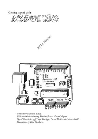
  • 1. Getting started with arduino Written by Massimo Banzi. With materials written by Massimo Banzi, Erica Calogero, David Cuartielles, Jeff Gray, Tom Igoe, David Mellis and Cristian Nold. Illustrations by Elisa Canducci. B E T A V e r s i o n
  • 2. 2 Thanks The Arduino team is composed of: Massimo Banzi, David Cuartielles, Tom Igoe, David Mellis and Gianluca Martino. The Arduino team would like to thank the following people and institutions for the support in making this booklet: Aliadi Cortelletti for typesetting the booklet. Barbara Ghella, Stefano Mirti, Claudio Moderini. Interaction Design Lab, Milano Domus Academy, Milano Interaction Design Institute, Milano Malmö University, Faculty of Art, Culture and Communication (K3) This booklet is released under a Creative Commons License: Attribution-NonCommercial-ShareAlike 2.5 You are free: * to copy, distribute, display, and perform the work * to make derivative works Under the following conditions: * You must attribute the work in the manner specified by the author or licensor. * You may not use this work for commercial purposes. * If you alter, transform, or build upon this work, you may distribute the resulting work only under a license identical to this one. * For any reuse or distribution, you must make clear to others the license terms of this work. * Any of these conditions can be waived if you get permission from the copyright holder. http://creativecommons.org/licenses/by-nc-sa/2.5/deed.en
  • 3. 3 arduino Index Introduction 4 / what is interaction design ? 5 / what is physical computing ? 5 the arduino way 7 / tinkering 8 / patching 9 / circuit bending 10 / keyboard hacks 11 / we love junk 12 / hacking toys 13 / collaboration 14 / the arduino hardware 15 / the software (IDE) 16 really getting started... 19 / the interactice device 19 / sensors and actuators 19 / basic introduction to programming 20 / blinking an LED 23 / what is electricity ? 25 / the breadboard 28 / reading a push button 30 / trying out different on~off sensors 32 / use the light sensor instead of the pushbutton 33 / analogue inputs 34 / try dufferent resistive sensors 36 / serial communication 37 / analogue inputs (PWM) 39 / driving bigger loads (motors, lams, etc…) 40 / complex sensors 42 / talking to software 43
  • 4. 4 Introduction Arduino is an open-source physical computing platform based on a simple i/o board and a development environment that implements the Processing language. Arduino can be used to develop stand-alone interactive objects or can be connected to software on your computer (e.g. Flash, Processing, Max/MSP). The boards can be assembled by hand or purchased preassembled; the open-source IDE can be downloaded for free. Arduino is different from other platforms that can be found on the market because of these features: The Arduino Project was developed out of an educational environment and is therefore great for newcomers to get things working quickly. It is a Multi Platform environment; it can run on Windows, Macintosh and Linux. It is Based on the Processing programming IDE It is programmed via a USB cable not a serial port. This is useful because many modern computers don’t have serial ports anymore. It is Open Source hardware and software - If you wish you can download the circuit diagram, buy all the components, and make your own, without paying anything to the makers of Arduino. The hardware is cheap. The USB board cost about EUR 20 and replacing a burnt out chip on the board is easy and costs no more than EUR 5. So you can afford to make mistakes. There is an active community of users so there is plenty of people who can help you. What does this all mean? We’re going to discover it this through this booklet that is designed to help designers and artistis to understand what benefits they can get from learning how to use the Arduino platform and adopting its philosophy.
  • 5. 5 / what is interaction design? There are many definitions of Interaction Design but the one that I like the most is simply “Interaction Design is about the design of any interactive experience”. In today’s world this generally is about the creation of meaningful between us (humans) and artefacts. We also like to explore the creation of beautiful and maybe even controversial between technology and us. Specifically we believe in designing through an iterative process based on prototypes of ever increasing fidelity. This approach ,also part of some types of “conventional” design, can be extended to include prototyping with technology and in particular with electronics. This particular brand of Interaction Design is called Physical Computing (or Physical Interaction Design). This booklet is in no way a substitute for a book on Physical Computing, we recommend you buy Tom Igoe’s excellent “Physical Computing” book. / what is physical computing? Physical Computing is about prototyping with electronics, turning sensors, actuators and microcontrollers into materials for designers and artists. It involves the design of interactive objects that can communicate with humans using sensors and actuators controlled by a behaviour implemented as software running inside a microcontroller. In the past using electronics meant having to deal with engineers all the time and this kept the designer from playing directly with the medium. Most of the tools were meant for engineers and required extensive knowledge. In recent years microcontrollers (small computers on a single chip) have become cheap and easier to use allowing the creations of better tools. The work that we have done with Arduino is to try to bring these tools one step closer to the beginner allowing people to start building stuff after only 3 or 4 days of workshop. With Arduino the designer or artist can get to know the basics of electronics and sensors very quickly and start building prototypes with an investment of as little as 70EUR.
  • 6. 6 From the punk-zine “sniffin’ glue” England, circa 1977
  • 7. 7 The Arduino Way The Arduino philosophy is based on making design rather then talking about it. It is a constant search for faster and more accurate ways to build better prototypes. We have explored many prototyping techniques and developed ways of thinking with our hands. The classic engineering relies on a strict process for getting from A to B while the Arduino way is based on maybe getting lost in the way and finding C instead. This is the process of tinkering that we are so fond about; playing with the medium in an open-ended way, finding the unexpected. In this search we also selected a number of software packages that enable that process, this constant manipulation of the software and hardware medium. Another concept we developed is the “opportunistic prototyping”: why spend time and energy building from scratch, a process that requires time and profound technical knowledge, while we can take already made devices and hack them in order to exploit the hard work done by large companies and good engineers? This become evident in Ivrea where the heritage of Olivetti is represented by a few junkyards where computer parts, electronic components and devices of any sort have been dumped after the demise of the Italian company. We could buy those devices for a few euros and hack them into our prototypes dramatically shortening the loop. The last element is the community. Engaging people and push them to share by being the first to share. We’re standing on the shoulders of the giants of open source here. In the next few paragraphs you can see some of our references that have inspired the “Arduino Way”.
  • 8. 8 / tinkering We believe it is essential to play with the medium, exploring different possibilities directly on the hardware and software, sometimes without a very defined goal. We call this process Tinkering. An exhibition that took place at the Exploratorium in 2004 had the best definition of it: Tinkering is what happens when you try something you don’t quite know how to do, guided by whim, imagination, and curiosity. When you tinker, there are no instructions - but there are also no failures, no right or wrong ways of doing things. It’s about figuring out how things work and reworking them. Contraptions, machines, wildly mismatched objects working in harmony - This is the stuff of tinkering. Re-using existing technology is one of the best ways of tinkering. Getting cheap toys or old discarded equipment and hacking them to make them do something new is one of the best ways to get to great results.
  • 9. 9 / patching Robert Moog built his analogue synthesizers in a modular fashion and the musician could try endless combination by “Patching” together different modules with cables. This made the synthesizer look like an old telephone switch but, combined with the numerous knobs, was the perfect platform for tinkering with sound and innovating music. This technique has been translated into the world of software by programs like Max or Pure Data.
  • 10. 10 / circuit bending Circuit bending is one of the most interesting forms of tinkering. It’s the creative short-circuiting of low voltage, battery-powered electronic audio devices such as guitar effects, children’s toys and small synthesizers to create new musical instruments and sound generators. The heart of this process is “the art of chance”. It began in 1966 when Reed Ghazala by chance, shorted-out a toy amplifier against a metal object in his desk drawer, resulting in a stream of unusual sounds.
  • 11. 11 / keyboard hacks Taking apart a keyboard reveals a very simple (and cheap) device. The Heart of it is this small board. By replacing the keyboard matrix with sensors we can implement new ways to interact with software. This is a key hardware component to learn about when starting in Physical Computing.
  • 12. 12 / we love junk One of the best ways to quickly get to results is to find a great source of technology junk and use it to quickly (and cheaply) get to prototype an experience. Accumulate junk and go through it before starting to build something from scratch.
  • 13. 13 / hacking toys Toys are a fantastic source of cheap technology to hack and reuse. The best interpretation of this way of working comes from Husman Haque and Adam Somlai-Fisher that, with their “Lowtech sensors and actuators” project, have perfectly described this technique.
  • 14. 14 / collaboration Collaboration between users is one of they key points in the Arduino world, through the forum people from different parts of the world hel each other while learning about the platform. The Arduino team encourages people to collaborate also at a local level by helpig them to seutp users groups in every city they visit.
  • 15. 15 / the arduino hardware This is a picture of the Arduino board. At the beginning you might be a bit confused with all those connectors. Here is an explanation of what every element of the board does: 14 Digital IO (pins 0 - 13,) can be inputs or outputs as set in software. 6 Analogue In (pins 0 - 5) are dedicated analogue input pins. These take analogue values (i.e. voltage readings) and convert them into a number between 0 and 1023. 3 Analogue Out (pins 9, 10, 11) these are actually 3 of the digital pins that can be reassigned to do analogue output. The board can be powered from your USB port or from the power socket. This setting can be changed with the jumper marked SV1 in the diagram. If the jumper is closest to the USB plug then the board is powered from there. If the jumper is on the 2 pins closest to the DC connector then it is powered from there.
  • 16. 16 / the software (IDE) The last component of Arduino is the software. This is a special program running on your computer that allows you to write programs for the Arduino board in a simple language modelled after the Processing language. The magic happens when you press the button that uploads the program to the board: the code you have written is translated into C language, that is normally quite hard to use for a beginner, and passed on to the avr-gcc compiler, an important piece of open-source software that makes the ultimate translation into the language understood by the microcontroller. This last step is quite important because it’s where Arduino is making your life simple and hiding away as much as possible of the complexities of programming microcontrollers. Downloading and installing the software In order to program the Arduino board you need to download the development environment (IDE) from here: http://www.arduino.cc/en/Main/Software Choose the right version for your operating system. Download the file and uncompress it. The first thing to do is to install the drivers that allow your computer to talk to your board through the USB port. Macintosh: Look for the “Drivers” folder inside the “arduino-0004” folder and double-click on the file called FTDIUSBSerialDriver_v2_0_1.dmg. When this has opened, install the software contained in the FTDIUSBSerialDriver.pkg. At the end of this process you’ll have to restart your machine to make sure the drivers apre properly loaded. After the installation is successful you will also need to run the command called “macosx_setup.command” Follow the instructions provided by the program and type the password that you use to login into your computer when asked. After this program has run successfully you need to turn off your computer. Don’t just reboot or logout, really turn it off and back on again. When this phase is over you can plug the board into the computer. Windows: Unzip the file called [FIXME] contained in the Drivers directory into a directory you can easily find later on. Plug the board into the computer and, when the [FIXME] New Device Found [/FIXME] window comes up, specify the location for the install wizard to look for the drivers. This will happen twice because the first time the computer installs the low level driver
  • 17. 17 then a piece of code that makes the board look like a serial port. Once the drivers are installed we can launch the development environment and start using Arduino. Using the development environment After the application has come up you will see a window like this one Firstly, you need to find out which port your device is connected to Macintosh: From the “Tools” menu select “Serial Port” and select the port that begins with “/dev/ cu.usbserial-“. The last 3 characters identify which one is the USB port the board is plugged to and change if you plug arduino into a different port.
  • 18. 18 [PIC screenshot of the Tools / Serial Port menu showing the list of ports] Windows: On Windows the process is a bit complicated at the beginning. Opening the “device manger” from: Start menu -> Control Panel -> System.. -> Hardware -> Device Manager Look for the device in the list under “Ports (COM & LPT)”. Arduino will come up as an “USB Serial Port” and will have a name like COM4. [PIC screenshot of the device manager showing arduino] Note: For some reasons on some windows machine the COM port has a number greater than 9 and this creates some problems when Arduino is trying to communicate with it. Check in the Arduino troubleshooting section of the website how to fix that. Then in the IDE, select the appropriate port from the Tools / Serial Port menu. Now the Arduino development environment can talk to the Arduino board and program it.
  • 19. 19 Really Getting Started with Arduino Now that we have introduced the Arduino philosophy and its components we are ready to make something happen with your board. In the following pages we will go through a few examples of the basic things you can do with Arduino. At the end of these exercises you are ready to experiment on your own. / the interactive device Most of the objects we will build using the Arduino board follow a very simple pattern that we call the “Interactive Device” It’s an electronic circuit that is able to sense the environment using components called “sensors” and processing the information through ”behaviour” implemented as software. The device will then be able to interact back with the world using “actuators”. / sensors and actuators Sensors and Actuators are electronic components that allow a piece of electronics to interact with the world. Since the microcontroller is a very simple computer it can only process electric signals (a bit like the electric pulses that are sent between neurons in our brains) in order to enable it to sense light, temperature or other physical quantities it needs something that can convert them into electricity. In our body the eye, for example, converts light into signals that get sent to the brain using nerves while in the electronic we could use a simple device called LDR that can measure the amount of light that hits it and report it back as a signal that can be understood by the processor. [PIC LDR.tiff] Once the sensors have been read the device has the information needed to “decide” how to react. This is done through Actuators. These are electronic components that can convert an electric signal into a physical action. For example in 0ur bodies, muscles receive electric signals from the brain and convert them into a movement while in the electronic world this functions could be performed by an electric motor. [PIC motor_fan.tiff] In the next chapters we will see how to read sensors of different types and control different kinds of actuators.
  • 20. 20 / basic introduction to programming Some of you may never have programmed before, if you have you may skip this part. Programming is about translating the behaviour we have in mind for our device into instructions that can be understood by the processor. In reality the processor uses a very detailed and very low-level language so through time “high level” languages have been developed. These are a bit more close to human languages than instructions like lda 0x0f Let’s see how we would go about translating a simple behaviour into a piece of program. A simple programme can always be mocked up as sentence, for example: When it is very dark I want the light to go on and the motor to start turning slowly We could then rewrite this into “pseudo code” (something that looks more like a program but it’s still human language): If light level is less than 50 then Turn Light on Turn motor on slow Loop again We quickly realise that we need two types of programming structures: loops and conditional statements. A loop is necessary to allow the processor to continually read the states of its inputs as well as to update the states of its outputs. Conditional statements will be used to check for certain conditions and change the course of the program depending on them. So the basic Arduino program looks like this: // This is a comment // variable declaration int x; void init() { // put code here } void loop () { // put code here }
  • 21. 21 At the beginning of the program we declare variables, areas of memory used to store data. Then the void init() function is used to setup the program (define which pins on the processor are inputs and which one are outputs etc) The last function, void loop(), will then be executed indefinitely until you turn the Arduino board off. So this is where we want all our conditional logic to be stored. It is the real program and where we can control the flow of the program. The text beginning with // is a comment, it’s very useful for you to remind yourself what your code does when you re-open it after a while or for other people Variables One special thing about programming is that every time you want to store some value you need to use a variable that you have to declare. That is, tell the computer what kind of value to expect. There are a few basic data types that a computer can expect that we will go through here: int an integer is a whole number i.e. 1,2,3,5 etc. byte an integer number between 0 and 255, this is useful if you need to save memory because it uses only 1 byte of memory. (Remember that the arduino board has only 1024 bytes of RAM) For most of the programming you will be doing, these data types will be all you need, to go into more detail, see: [URL of arduino reference] Flow control If [condition] Then In Arduino, an if statement looks like this: if(expression) { statement; statement; } Where the expression could be one of the following: a == b a equals b a != b a is not equal to b a > b a is greater than b a < b a is less than b a =< b a is less than or equals to b a >= b a is greater than or equals to b
  • 22. 22 (N.B. do not confuse == with the assignment operator = that actually changes the value of the variable to the left of it, this can be very dangerous!) Statements can be anything you like (including more conditional statements). For loops for (i=1; i <= 8; i++) { statement; } A for loop is a way to execute a certain piece of code for a very specific amount of times. In the example shown “statement” is executed 8 times with “i” going from 1 to 8. Note In Arduino you don’t need to initialise the local variable i. However in java-based languages like Processing you add int in front of the first instance of i. Delays delay(100) // The delay() function is useful for embedded programming to slow down the rate at which the processor updates. This is used to make thing happens at a certain rate, for example if we want to blink and led every second, after we turn it on we can place a delay(1000) which will make the processor sit there and do nothing for a second (1000 milliseconds) Delay is also useful in debugging and general flow control.
  • 23. 23 / blinking an LED This program is the first code to run to test that your Arduino board is working and configured correctly. Type the following text into your Arduino editor. Now that the code is in your IDE we need to verify it and upload it to the board. Press the “Verify” button and if everything is correct you’ll see the message “Done compiling” appear at the bottom of the program text. At this point we can upload it into the board: press the reset button on the Arduino board, this forces the board to stop what it’s doing and listen for instructions coming from the USB port. Now we have about 6 or 7 seconds to press the “Upload to I/O Board” button. this sends the current program to the board that will store it in its memory and eventually run it. You will see a few messages appear in the black area at the bottom of the window, these are messages that make it easier to understand if the process has completed correctly. There are 2 LEDs marked RX and TX on the board, they flash every time a byte is sent or received by the board. During the download process they keep flickering, if this doesn’t happen it means there is some communication problem or you haven’t selected the right port in the “Tools / Serial Port” menu. /* Blinking LED * ------------ * * turns on and off an LED connected to pin 13 * */ int ledPin = 13; // LED connected to // digital pin 13 void setup() { pinMode(ledPin, OUTPUT); // sets the digital // pin as output } void loop() { digitalWrite(ledPin, HIGH); // turns the LED on delay(1000); // waits for a second digitalWrite(ledPin, LOW); // turns the LED off delay(1000); // waits for a second }
  • 24. 24 Assuming that program has been uploaded correctly connect an LED to the pins 13 and GND on the board like you see in the illustration.
  • 25. 25 / what is electricity If you have ever done any plumbing at home, electronics won’t be a problem for you to understand. Jokes aside, in order to understand how electricity and electric circuits work the best way is to build a mental model called the “water analogy”. Let’s take a simple device like a portable fan, if you take it apart you will see that it contains a small battery a couple of wires going to an electric motor and one of the wires is interrupted by a switch. Now makes sure you have a new battery fitted in the device and activate the switch; the motor will start to spin providing the necessary refreshment. How does this work? Well imagine that the battery is a water pump and the switch is a tap while the motor is one of those wheels you see in watermills, when you open the tap water will flow from the pump and push the wheel into motion. Now in this simple hydraulic system two parameters are important: the pressure of the water (this is given from how powerful is the pump) and the amount of water that will flow in the pipes (this depends from the size of the pipes and the resistance that the wheel will oppose to the stream of water hitting it).
  • 26. 26 You quickly understand that if you want the wheel to spin faster you need to increase the size of the pipes (but this works only up to a point) and increase the pressure that the pump can achieve. Increasing the size of the pipes allows more flow of water to go through them, effectively by making them bigger we have reduced the resistance they oppose to the flow of water. This works until a certain point where the wheel won’t spin any faster because the pressure of the water is not strong enough and this is when we need the pump to be stronger. This can go on until the point when the wheel falls apart because the water flow is too strong and destroys it. Another thing you will notice is that as the wheel spins the axle will heat up a little bit, this is because no matter how good is the way we have mounted the wheel the attrition between the axle and the holes it is mounted in will generate heat. This is important to understand that in a system like this not all the energy you pump into the system will be converted into movement, some will be lost in a number of inefficiencies and will generally show up as heat emanating from some parts of the system. So what are the important parts of the system as we described it before? The pressure produced by the pump is one, the resistance that the pipes and wheel oppose to the flow of water and the actual flow of water (let’s say that this is represented by the number of litres of water that flow in one second) are the others. Without going into much details electricity works a bit like water, you have a kind of pump (any source of electricity like a battery or a wall plug) pushes electric charges (imagine them like “drops” of electricity) down pipes represented by the wires where some devices are able to use them to produce heat (your grandma’s thermal blanket)
  • 27. 27 light (your bedroom’s lamp) sound (your stereo) movement (your fan) and much more. So when you read on a battery 9V you can imagine the Voltage of the battery like the water pressure that can be potentially produced by this little “pump”. This is measured in Volts from Alessandro Volta, the inventor of the first battery. The flow of water has got and electric equivalent called “current” that is measured in Amperes from Andre Marie Ampere. Finally the resistance opposed to the flow of current by any means it travels through is called, yes you guessed right, resistance and it’s measured in Ohms from the German physicist Ohm. Mr ohm is also responsible for coming up with the most important law in electricity and the only formula you will really need to remember. He was able to demonstrate that in a circuit the Voltage, the Current and the Resistance are all related to each other and in particular that the resistance opposed by the circuits determines the amount of current that will flow through it give a certain supply voltage. It’s very intuitive if you think about it: Take a 9V battery and plug it into a simple circuit while measuring current, you will find that the more resistors you add to the circuit the less current will travel through it. Going back to the water flowing in pipes, given a certain pump if I place a tap (which we can assimilate to a variable resistor in electricity) the more I close the tap, increasing resistance to water flow, less water will flow through the pipes. Mr Ohm summarised his law into this formulas: R (resistance) = V (voltage) / I (current) V = R * I I = V / R This is the only rule that you really have to memorise and learn to use, because in most of your work this will be the only one you will really need.
  • 28. 28 / the breadboard The process of getting a circuit to work is largely based on making lots of changes to it until it behaves properly; it’s a very fast iterative process that could be seen as the electronic equivalent to sketching. The design evolves in your hands as you try different combinations. In order to achieve the best results you want to use a system that will allow you to change the connections between components in the fastest, most practical and non-destructive way. This requirement clearly rules out soldering, it’s a time consuming procedure that puts every component under stress every time you heat them up and cool them down. The answer to our problems comes from a very practical device called “Solder-less Breadboard”. As you can see from the picture it’s a small plastic board full of holes, each one of them contains a spring-loaded contact. You can push a component’s leg into one of the hole and it will establish an electrical connection with all the other holes in the same vertical column of holes. Each hole is at a distance of 2.54 mm distance from the others, since most of the components have their legs, known to techies as pins, are spaced at that standard distance therefore chips with multiple legs will fit nicely. Not all the contacts on a breadboard are created equal, there are some differences: the topmost and bottom row (coloured in red and blue and aptly marked with + and -) are
  • 29. 29 connected horizontally and are used to carry the power across the board so that when we need power or ground we can provide it very quickly with a short jumper (this is not a sweater or a funny insect but a short piece of wire used to connect two points in the circuits) The last this you need to know about breadboards is the in the middle there is a large gap that is as wide as the size of a small chip. This shows that the each vertical line of holes is interrupted in the middle so that when you plug a chip you won’t short circuit pins that are on the two sides of the chip, clever eh?
  • 30. 30 / reading a pushbutton Now we’re going to see how Arduino is able to receive input from the external world. This is done with the digitalRead() function which, given the number of a pin, will tell you if there is a voltage applied to it. If the voltage is 2.5 or more volts, digitalRead() will return HIGH while if there is no voltage it will return LOW. This code checks the state of the digital pin and turn on the LED if the button is pressed. Very simple and will get you started very quickly, just build the circuit you see in the next page. /* Blink LED when the button is pressed * ------------------------ */ int ledPin = 13; // choose the pin for the LED int inPin = 7; // choose the input pin // (for a pushbutton) int val = 0; // variable for reading the pin status void setup() { pinMode(ledPin, OUTPUT); // declare LED as output pinMode(inPin, INPUT); // declare pushbutton as input } void loop(){ val = digitalRead(inPin); // read input value // check if the input is HIGH (button released) if (val == HIGH) { digitalWrite(ledPin, LOW); // turn LED OFF } else { // blink the LED and go OFF digitalWrite(ledPin, HIGH); delay(200); digitalWrite(ledPin, LOW); delay(1000); } }
  • 31. 31
  • 32. 32 / trying out different on/off sensors Now that you’ve used the push-button you can replace it with a lot of different sensors that have the same type of output: a contact that closes and opens. One good example is the tilt sensor, this is a simple electronic component that contains two contacts and a little metal ball. [PIC of tilt sensors] When the sensor is in its upright position the ball bridges the two contacts and this is like when you press the push-button. When you tilt this sensor the ball moves and the contact is opened like when you release the push-button. Using this simple component you can implement, for example, gestural interfaces that react when an object is moved or shaken. Another sensor you might want to try is the infra-red sensor from burglar alarms (also known as PIR sensor). [PIC of PIR sensors] This small device triggers when a human being is moving in its proximity. It’s a simple way to detect the presence of people. You should now experiment by looking at all the possible devices that have two contacts that close, like the thermostat that is used in apartments to set the room temperature or just placing two wires next to each others and dropping water onto them.
  • 33. 33 / use the light sensor instead of the pushbutton Now we’re going to try an interesting experiment: take a light sensor like the one pictured here. This is an LDR or light dependent resistor, this means that in darkness its resistance is quite high while when you shine some light at it the resistance quickly drops and it becomes a reasonably good conductor of electricity. Now plug the LDR in place of the push-button, you will notice that if you cover or uncover it with your hands the LED turns on and off. You’ve just built your first sensor driven LED.
  • 34. / analogue inputs As we have seen in the previous section Arduino is able to detect if there is a voltage applied to one of its pins and report it trough the digitalRead function. This is fine in a lot of applications but the light sensor that we have used before it’s also able to tell us not just if there is light or not, it’s also able to tell us how much light there is. This is the difference between an on/off sensor (simply telling us if something is there or not) and an analogue sensor whose value continuously changes. In order to read this type of sensors we need a different type of pin. In the lower-right part of Arduino you’ll see 6 pins marked “Analog In”, these are special pins that not only can tell us if there is a voltage applied to them or not but also it value. By using the analogRead function we can read the voltage applied to one of the pins. This function returns a number between 0 and 1023 representing voltages between 0 and 5 volts. For example if there is a voltage of 2.5 volts applied to pin 0 writing analogRead(0) will return 512 etc etc. If you now build the circuit that you see in the illustration by using a 10k or 4.7k resistor and you run the piece of code you find here you’ll see the led blinking at a rate that’s dependent on the amount of light that hits the sensor. 34
  • 35. 35 /* Analog Read to LED * ------------------ * copyleft 2005 David Cuartielles * */ int sensorPin = 0; // select the input pin for the // potentiometer int ledPin = 13; // select the pin for the LED int val = 0; // variable to store the value coming // from the sensor void setup() { pinMode(ledPin, OUTPUT); // ledPin is as an OUTPUT } void loop() { val = analogRead(sensorPin); // read the value from // the sensor digitalWrite(ledPin, HIGH); // turn the LED on delay(val); // stop the program for // some time digitalWrite(ledPin, LOW); // turn the LED off delay(val); // stop the program for // some time }
  • 36. 36 / try different resistive sensors Using the same circuit that you have seen in the previous section you can connect a lot of other resistive sensors tha work more or less in the same way. For example you could connect a thermistor. This is a simple device whose resistance changes with temperature. In the circuit we have shown you changes in resistance become changes in voltage that can be measured by Arduino. Be aware that there isn’t a direct connection between the value you read the actual temperature measured. If you need an exact reading you should read the numbers that come out of the analogue pin while measuring with a real thermometer. You could put these numbers side by side in a table and work out a way to figure out what is the relationship between the values. Up until now we have just used an LED as an output device but how do we read the actual values that Arduino is reading from the sensor? Certainly we can’t make the board blink the values in morse code. For this type of issues we can use Serial Communication that is described in the next chapter.
  • 37. 37 / serial communication We have seen at the beginning of the booklet that Arduino has an USB connection that is used by the IDE to upload code into the processor. The good news is that this connection can also be used by the programmes we write in Arduino to send data back to the computer or receive commands from it. For this purpose we are going to use the Serial object. This object contains all the code we need to send and receive data. We’re now going to use the last circuit we have built using the the the thermistor and send the values read back to the computer.
  • 38. 38 Type this code into a new sketch: int sensorPin = 2; // select the input pin for the // potentiometer int val = 0; // variable to store the value coming // from the sensor void setup() { Serial.begin(9600); // open the serial port to send // data back to the computer at // 9600 bits per second } void loop() { val = analogRead(sensorPin); // read the value from // the sensor Serial.println(val); // print the value to // the serial port delay(100); } Now that we have the program running you should press the “Serial Monitor” button on the Arduino IDE and you’ll see the numbers lining up in the bottom part of the window. Now any software that can read from the serial port can talk to Arduino.
  • 39. 39 / analogue output (PWM) With the knowledge that you have accumulated until now you could take up the task of building an interactive lamp, a lamp that can be controlled not just with a boring on-off switch but maybe in a bit of more poetic way. One of the limitations of the blinking LED examples we have seen until now is that you can only turn on and off the light while a fancy interactive lamp needs to be able to dim the light properly. To solve this problem we can use a little trick that makes a lot of things like TV or Cinema possible: Persistance of Vision.
  • 40. 40 Take the first LED blink example we have seen and now change the numbers in the delay function until you don’t see the LED blinking any more. You will see that the LED seems to be dimmed at 50% of its normal brightness. Now change the numbers so that the time the LED is on is ¼ of the time it’s off. Run the program and you’ll see the brightness is roughly 25%. This technique is called Pulse Width Modulation, a fancy name to say that if you blink the LED fast enough you don’t see it blink any more but you can change its brightness by changing the ration between the on time and the off time. Here is a small diagram showing how this works. This technique also works with other devices than the LED. For example you can change the speed of motor in the same exact way. While experimenting you will see that blinking the LED by hand is a bit inconvenient because as soon as you want to read a sensor or send data on the serial port the LED will flicker. Luckily enough the processor used by the Arduino board has a piece of hardware that can very efficiently blink 3 LEDs while your program does something else. This is implemented by pins 9, 10 and 11 that can be controlled by the analogWrite() instruction. For example writing analogWrite(9,128) will set to 50% the brightness of an LED connected to pin 9. Why 128? because analogWrite expects a number between 0 and 255 as a parameter where 255 means 100%. Having 3 channels is very good because if you buy red, green and blue LEDs you can might their light and make light of any colour you like!
  • 41. 41 / driving bigger loads (motors, lamps etc.) Each one of the pins on an Arduino board can be used to power devices that use up to 20milliamps, this is a very small amount of current, just enough to drive an LED and not much more. If you try to drive something like a motor the pin will immediately stop working and will potentially burn the whole processor. To drive bigger loads like motors or incandescent lamps we need to use an external component that can switch such things on and off driven by an Arduino pin. One of such devices is called a Mosfet Transistor, beyond the real meaning of the funny name, it’s an electronic switch that can be driven by applying a voltage to one of its three pins called “gate”. Effectively it can be seen like the light switch we use at home where the action our finger does to turn the light on and off is replaced by a pin on the arduino board sending voltage to the “gate” of the Mosfet. In the following picture you see how you would use a Mosfet like the IRF520 to turn on and off a small motor attached to a fan. You will also notice that the motor takes its power supply from the 9V connector on the Arduino board, this i another benefit of the Mosfet: it allows us to drive devices that have a power supply different from the one used by Arduino. Since the Mosfet is connected to pin 9 we can also use analogWrite() to control the speed of the motor through PWM..(There is a mistake in the drawing, the diode connect to the MIDDLE pin on the Mosfet)
  • 42. 42 / complex sensors We define “complex sensors” the one that produce a type of information that requires a bit more than a digitalRead() or an analogRead() to be used. These usually are small circuits that have already a small microcontroller inside that pre processes the information. In the illustration you can see an Ultrasonic Ranger, an Infrared Ranger and an Accelerometre. You can find examples on how to use them on our website in the “Tutorials” section.
  • 43. 43 / talking to software In this section we will show you how to use the data sent by an Arduino board through the USB port to a piece of software running in your computer. Virtual Etch a Sketch Arduino Code This project requires 2 varible resistors that we are using to control the X and Y axis respectively. The important thing here is how send out the data by prefacing it using the letters A or B for the two sensors. This method can be used to send the data from many different sensors. /* Virtual Etch A Sketch using 2 Potentiometers This program reads two analog sensors via serial and draws their values as X and Y Arduino Code Christian Nold, 22 Feb 06 */ int potPin = 4; // select the input pin for the potentiometer int potPin2 = 5; // select the input pin for the potentiometer int ledPin = 13; // select the pin for the LED int val = 0; // variable to store the value coming from the sensor int val2 = 0; // variable to store the value coming from the sensor void setup() { beginSerial(9600); pinMode(ledPin, OUTPUT); // declare the ledPin as an OUTPUT } void loop() { val = analogRead(potPin); // read the value from the sensor val2 = analogRead(potPin2); // read the value from the sensor printString(“A”); printInteger(val); // Example identifier for the sensor serialWrite(10); printString(“B”); printInteger(val2); // Example identifier for the sensor serialWrite(10);
  • 44. 44 } Virtual Etch a Sketch Processing Code This code looks for the letters A followed by the data and uses this for the X axis. Then it waits for letter B and uses this for the Y axis. The gradually fading line is implemented by repeatedly copying a semi transparent (alpha) black square over the stage. /* Virtual Etch A Sketch using 2 Potentiometers This program reads two analog sensors via serial and draws their values as X and Y Processing Code Christian Nold, 22 Feb 06 */ import processing.serial.*; String buff = “”; String temp = “”; float temporary = 0.0; float screenwidth = 0.0; float xCoordinate = 0; float yCoordinate = 0; int val = 0; int NEWLINE = 10; Serial port; void setup() { size(200, 200); strokeWeight(10); // fat stroke(255); smooth(); port = new Serial(this, “COM2”, 9600); // Change this to the correct serial port }
  • 45. 45 void draw() { fill(0,2); // use black with alpha 2 rectMode(CORNER); rect(0,0,width,height); while (port.available() > 0) { serialEvent(port.read()); } point(xCoordinate, yCoordinate); } void serialEvent(int serial) { if(serial != NEWLINE) { buff += char(serial); } else { if (buff.length() > 1) { temp = buff.substring(0, buff.length()-(buff.length()-1)); // this isolates just the beginning sensor identified if(temp.equals(“A”) == true) { //sensor A value temp = buff.substring(1, buff.length()); temporary = float(temp); xCoordinate = width/(1024/temporary); println(xCoordinate); } if(temp.equals(“B”) == true) { //sensor B value temp = buff.substring(1, buff.length()); temporary = float(temp); yCoordinate = height/(1024/temporary); println(yCoordinate); } // Clear the value of “buff” buff = “”; }