SlideShare ist ein Scribd-Unternehmen logo
1 von 22
Downloaden Sie, um offline zu lesen
THERMAL POWER PLANT
OPERATIONS
Simulator Part 3- Day2
MANOHAR TATWAWADI
Director, tops
A2-806, PALLADION, BALEWADI, PUNE 411045
Mob: 9372167165, Email:-mtatwawadi@gmail.com
05/10/2019 Manohar Tatwawadi 1
PRDS CHARGING
• Charge 16 ata header from other unit :
• Open Aux PRDS Drains 10% from Field.
• Put "PRDS CHARGE FROM OTHER UNIT" to 100 from field.
• Observe pressure in 16 ata header on Boiler Feed Pump &
PRDS' Panel.
• Observe temp. in 16 ata header on 'Condensate Panel‘.
• Same parameters also on Mimic page “Aux. PRDS System”.
• Open auxiliary steam valve by putting "AUX PRDS TO EJS AS-
1" to ON position from Field page.
• Open valve FW-83, FW-82, FW-77 (PRDS Spray) and AS-
51(PRDS Iso.) from Panel "Boiler feed pump and PRDS station"
• Open AS-81 (Steam to Ejector) and AS-79 (Gland Steam
Cooler)& GC-1 from Panel "Turbine Control/Lube oil Pump“.
05/10/2019 Manohar Tatwawadi 2
PRDS…… MIMIC
05/10/2019 Manohar Tatwawadi 3
CW SYSTEM
• Open CW-1, CW-2,CW-3,CW-4,CW-5,CW-6,CW-7 and
CW-8 from field page.
• CW Pump-A Local/Remote/Panel on remote, Start the
CW Pump A by switch on 'Condensate Panel‘
• Check Motor Current Graphics page 'Cooling Water
system'.
• NOTE: 1) If the pump is in local mode then, operate
the pump from Field page.
2) Corresponding valves for CWP-B are also on
same pages as CWP-A.
• Start C.T lift pump from field page.
05/10/2019 Manohar Tatwawadi 4
COOLING WATER SYSTEM
05/10/2019 Manohar Tatwawadi 5
Deaerator Heating
• Open Isolating Valves of AS-66,67,68 & 69 from Field page.
• Open Isolating Valves of AS-72 & AS-73 from Field Page.
• Open AS-72 to 30% from Panel and bring up the temperature
of feed water in deaerator to around 85-90 degree C. (Watch
Temp on Panel)
• Open manually to 30% AS-57 (bypass of AS-58) & AS-65 from
Panel. (16 ata auxiliary steam supply valve to deaerator.)
• Put Both Valves on Auto with SP on 6 Kg/sqcm.
• Start deaerating the incoming main condensate water into
deaerator by opening deaerator steam pressure regulating
valve.
• Start feed water heating in deaerator by regulating steam
valve AS-58 and bring up the temperature of feed water in
deaerator to around 85-90 degree C.
05/10/2019 Manohar Tatwawadi 6
FEED WATER SYSTEM
05/10/2019 Manohar Tatwawadi 7
BOILER FEED PUMPS
• For starting the boiler feed pump:
• Put L/R/P switch to Remote for both Aux. Oil Pump &
Boiler Feed Pump.
• Ensure Feed pump auto control in Manual mode & Feed
pump selection on DP mode from Panel-4
• Recirculation of Aux oil Pump and Warm up valve of BFP
should be open.
• BFP Scoop Position on Minimum. (30%)
• BFP 1P/2P on 1 Pump. And BFP A/B/C/ selection on
Manual
• Give “ON” command to BFP A
• Observe that the normalized current for BFP-A is 218
amps on panel-4.05/10/2019 Manohar Tatwawadi 8
BFP Panel
05/10/2019 Manohar Tatwawadi 9
BOILER FEED PUMPS
Observe the following :
• Warm up-line valve and AOP closes on interlock.
• Observe boiler feed pump suction flow (about 120t/hr) on trend
page “Desk 4 – BFP Parameters” .
• Observe that the boiler feed pump suction pressure is more than
about 5.8 Kg/cm2 on panel-5.
• Boiler feed pump discharge header pressure on panel-4
• The discharge valve indication on graphics "Feed Water System".
• If ELP is running then put it OFF from field page 4.
• Note the motor bearing temperatures along with oil pressure on
IMV page no. 1
• Observe pressure at inlet of feed regulating station on panel-5 and
open discharge valve FW-40 of BFP-A.
• Start feeding water to boiler drum by opening low load regulating
valve FW-26 in "manual mode" and increasing scoop tube position
such that a flow of about 50 t/hr at minimum feed pump discharge
pressure.
05/10/2019 Manohar Tatwawadi 10
Establishing FEED WATER FLOW
For establishing feed water flow to boiler
• Again observe the following:
• -BFP discharge header pressure
• -Deaerator level
• -Condenser hot well level
• -FW26 control from panel-4
• -Control Master & pump scoop from panel-4.
• -Observe feed water temperature and pressures.
05/10/2019 Manohar Tatwawadi 11
Establishing FEED WATER FLOW…
• -Keep a close watch a deaerator level and maintain at
3/4th of instrument scale by regulating DM make up
valves DM-24 or DM-25.
• -Keep a close watch on condenser hotwell and maintain at
3500 mm by regulating hot well level control valve MC-36
manually.
• -Maintain deaerator water temperature around 90 degree
C by deaerator feed tank heating valve AS-58.
• -Observe drum level on panel-4 or "Feed Water System "
graphics.
• -Bring down pump scoop tube position such that feed
pump discharge pressure is minimum (at least 5 Kg/cm2
more than low discharge pressure trip setting).
05/10/2019 Manohar Tatwawadi 12
Establishing FEED WATER FLOW…
• Keep on slowly raising deaerator temperature and pressure by
deaerator steam regulating valve AS-58 and gradually observe the rise in
pressure. Maintain the deaerator pressure at 6 kg/cm2 (7 ata).
• Put Drum level control, scoop in Auto mode.
• Make sure (3E,del p) switch position on del P position and (1E/3E) switch
position on 1E position.
• Make sure valve selection switch into Main position.
• Put BFP A scoop & BFP B scoop controller into manual mode of operation.
• Master scoop controller setpoint is on 50% settings.(CD-4) and in manual
mode.
• Increase output of master scoop controller till BFP a scoop setpoint
matches with its measured variable.
• Once the error becomes zero of BFP A scoop A then put BFP A scoop
controller into Auto mode.
• Adjust the master controller setpoint to match its measured variable and
put into auto mode from CD-4.
05/10/2019 Manohar Tatwawadi 13
CHARGING OF MAIN STEAM LINES
• Main steam line to be charged by opening MS-11 & M-12 from field
page no.11.
• Check : Put interlock selector switch of boiler drum emergency drain
valve in interlock mode from CD-4.OR Put Inching valve B-39 to 50%.
• Open the following drain valves from Field page no. 11
• -MS line drain to 10%
• -HPBP & LPBP line drains to 5%.
• -HPT casing & rotor drains to 5%.
• -IPT casing & rotor drains to 5%.
• Continuous blow down is on Imf page No.10.
• Keep a very close watch on boiler drum level and maintain it a
normal value (0 mm of scale) if so required, by low load feed
regulating valve FW-26.
• -drum level on panel-4.
• -Drum steam temp. on "Water & steam cycle" graphics.
• -Drum metal temp. on bargraph group=3, page=7, variable=3.
05/10/2019 Manohar Tatwawadi 14
Watching Drum Level & Flue Gas Temps.
• Observe the gradual rise in flue gas temperatures at exit, at
platen SH exit, at airheater exit, at economizer inlet, at
airheaters inlet and at airheaters exit. (Mimic Page No.1)
• Observe these parameters on trend page“Desk1–Flue gas
Temperatures”.
• Observe the gradual rise in air temperatures at air heaters
exit on trend page “Desk 1 - Flue Gas Temperatures”.
• Observe steam temperature on trend page “Desk4 – Drum
Parameters”.
• At about 2 kg/cm2 boiler drum pressure, close boiler drum
vents from field page no.13 and superheater vents and at
about 5 kg/cm2 of boiler drum pressure, throttle superheater
drains.
05/10/2019 Manohar Tatwawadi 15
Watching Drum Level & Flue Gas Temps
05/10/2019 Manohar Tatwawadi 16
CONDENSER VACUUM BUILDUP
• Check that non-return valves in CRH lines and their bypass valves (CR-3,
CR-4) are closed from Panel
• Close EV-1 & EV-2 from CD-5.
• Open airvent to condensors CA1 & CA2 from field page no.14.
• Open syphon filling valve MC-56 from field page no.9.
• Close vacuum breaker valve from panel-7
• Observe turbine rotor’s differential expansions on panel or trend page
no “Desk 7 – Turbine Expansions” .
• Open the ejector drain valve from field page no.12.Put gland seal steam
pressure controller valve(AS-81) with setpoint of .2kg into auto mode
from Panel 7. from field page no.14 to charge the gland sealing system
from panel-6.
• Open the valve on air line to starting ejector CA-5 from panel-6 & observe
graphics "Vacuum raising".
• Start starting ejector by opening its steam supply valve AS-4 to 50%
(Panel 7) .
• Observe the condenser vacuum on panel 6. It will take approx.3 to 5min
for vacuum to start.05/10/2019 Manohar Tatwawadi 17
CR1, CR2, CR3 & CR4 NRVs
MS & CRH
NRVs
05/10/2019 Manohar Tatwawadi 18
VACUUM RAISING
05/10/2019 Manohar Tatwawadi 19
Vacuum Raising
• Vacuum pulling has now started.
• When the vacuum is around 30-35 mm of Hg.cl (about 0.04
kg/cm2) take gland cooler No. 1 steam ejector in service by
opening steam supply valve to glands (AS-9,AS-10,AS-11,AS-
12,AS-13 & AS-14) from Field page no.14 such that, vacuum
of about 450-500 mm is available at GC-1 ejector.
• Close drains of Steam lines to starting ejector and to main
ejectors and GSC-1 from Field page no. 12
• When the vacuum is around 50-60 mm of Hg.cl. (about .07
kg/cm2) admit steam to turbine gland seals by opening
gland seal pressure regulating valve such that a pressure of
about 0.15 kg/cm2 to 0.20 kg/cm2 is available in seal steam
header.
05/10/2019 Manohar Tatwawadi 20
GLANDS SEALING
• Check that gland steam temperature is between 130-1500 C.
• Put the control of turbine gland sealing steam pressure
regulating valve AS-05 on `Auto‘ from Control Panel 7.
• The rate of vacuum pulling would become faster when gland
sealing steam is admitted.
• Start both main ejectors by opening their steam supply valve
(AS-2, AS-3) from Panel 7 to speed up the vacuum pulling rate.
• Open CA-3 and CA-4 from field page no.14.
• Open DM48,DM46,DM49,DM47 from field page no.12 on IC.
• Observe Mimic "Air Ejection System"
• When the vacuum in condenser is around 580 mm of Hg (about
0.76 kgcm-2) stop starting ejector first by closing its air line
valve CA-5 and then closing its steam Supply valve AS-4. Vacuum
continues to rise.
05/10/2019 Manohar Tatwawadi 21
05/10/2019 Manohar Tatwawadi 22

Weitere ähnliche Inhalte

Was ist angesagt?

Unit lightup synchronisation & shutdown
Unit lightup synchronisation & shutdownUnit lightup synchronisation & shutdown
Unit lightup synchronisation & shutdown
Nitin Mahalle
 
INTRODUCTION TO GOVERNING
INTRODUCTION TO GOVERNINGINTRODUCTION TO GOVERNING
INTRODUCTION TO GOVERNING
SURAJ KUMAR
 
Energy adudit methodology for boiler
Energy adudit methodology for boilerEnergy adudit methodology for boiler
Energy adudit methodology for boiler
Kongkiert Tankayura
 

Was ist angesagt? (20)

Handling of turbine side emergencies
Handling of turbine side emergenciesHandling of turbine side emergencies
Handling of turbine side emergencies
 
Construction of 500 MW Steam Boiler
Construction of 500 MW Steam BoilerConstruction of 500 MW Steam Boiler
Construction of 500 MW Steam Boiler
 
Boiler light up & loading
Boiler light up & loadingBoiler light up & loading
Boiler light up & loading
 
Starting & Recommended Interlocks for AH,ID,FD,PA Fans & BD Valves for 270 MW...
Starting & Recommended Interlocks for AH,ID,FD,PA Fans & BD Valves for 270 MW...Starting & Recommended Interlocks for AH,ID,FD,PA Fans & BD Valves for 270 MW...
Starting & Recommended Interlocks for AH,ID,FD,PA Fans & BD Valves for 270 MW...
 
660 mw turbo governing & protection system
660 mw turbo  governing & protection system660 mw turbo  governing & protection system
660 mw turbo governing & protection system
 
Boiler Reheater protection
Boiler Reheater  protectionBoiler Reheater  protection
Boiler Reheater protection
 
boiler turbine emergency
boiler turbine emergencyboiler turbine emergency
boiler turbine emergency
 
steam turbine turbine interlocks for (KWU turbine)
steam turbine turbine interlocks for (KWU turbine)steam turbine turbine interlocks for (KWU turbine)
steam turbine turbine interlocks for (KWU turbine)
 
THERMAL POWER PLANT OPERATIONS
THERMAL POWER PLANT OPERATIONSTHERMAL POWER PLANT OPERATIONS
THERMAL POWER PLANT OPERATIONS
 
Power Plant Simulator Day 3 Part 5
Power Plant Simulator Day 3 Part 5Power Plant Simulator Day 3 Part 5
Power Plant Simulator Day 3 Part 5
 
Unit lightup synchronisation & shutdown
Unit lightup synchronisation & shutdownUnit lightup synchronisation & shutdown
Unit lightup synchronisation & shutdown
 
Hp/ lp bypass system for steam turbines
Hp/ lp bypass system for steam turbinesHp/ lp bypass system for steam turbines
Hp/ lp bypass system for steam turbines
 
Turbine Stress Control Logic, Calculation & Working
Turbine Stress Control Logic, Calculation & WorkingTurbine Stress Control Logic, Calculation & Working
Turbine Stress Control Logic, Calculation & Working
 
INTRODUCTION TO GOVERNING
INTRODUCTION TO GOVERNINGINTRODUCTION TO GOVERNING
INTRODUCTION TO GOVERNING
 
Lmw turbine oprn. manual
Lmw turbine oprn. manualLmw turbine oprn. manual
Lmw turbine oprn. manual
 
Pulverized coal fired boiler startup procedure
Pulverized coal fired boiler startup procedurePulverized coal fired boiler startup procedure
Pulverized coal fired boiler startup procedure
 
Energy adudit methodology for boiler
Energy adudit methodology for boilerEnergy adudit methodology for boiler
Energy adudit methodology for boiler
 
210 MW BHEL Turbine Cycle Heat Balance
210 MW BHEL Turbine Cycle Heat Balance210 MW BHEL Turbine Cycle Heat Balance
210 MW BHEL Turbine Cycle Heat Balance
 
660 mw turbo generator & its auxiliaries
660 mw turbo generator & its auxiliaries660 mw turbo generator & its auxiliaries
660 mw turbo generator & its auxiliaries
 
Cfbc boiler startup and shutdown
Cfbc boiler startup and shutdownCfbc boiler startup and shutdown
Cfbc boiler startup and shutdown
 

Ähnlich wie POWER PLANT SIMULATOR 210 MW

Training on OJT of Boiler Operation00.pdf
Training on OJT of Boiler Operation00.pdfTraining on OJT of Boiler Operation00.pdf
Training on OJT of Boiler Operation00.pdf
Madan Karki
 
49539990 burner-management-system
49539990 burner-management-system49539990 burner-management-system
49539990 burner-management-system
Mowaten Masry
 

Ähnlich wie POWER PLANT SIMULATOR 210 MW (20)

Thermal Power Plant Simulator Operations Training
Thermal Power Plant Simulator Operations TrainingThermal Power Plant Simulator Operations Training
Thermal Power Plant Simulator Operations Training
 
210 MW simulator, loading to full 210 MW
210 MW simulator, loading to full 210 MW210 MW simulator, loading to full 210 MW
210 MW simulator, loading to full 210 MW
 
PUMPS.ppt
PUMPS.pptPUMPS.ppt
PUMPS.ppt
 
new prentation.pptx
new prentation.pptxnew prentation.pptx
new prentation.pptx
 
Plant Air & Inst Air.ppt
Plant Air & Inst Air.pptPlant Air & Inst Air.ppt
Plant Air & Inst Air.ppt
 
Final Turbine rolling ppt Akshay.pptx
Final Turbine rolling ppt Akshay.pptxFinal Turbine rolling ppt Akshay.pptx
Final Turbine rolling ppt Akshay.pptx
 
Boiler p&i
Boiler p&iBoiler p&i
Boiler p&i
 
Hplpbp
HplpbpHplpbp
Hplpbp
 
Urea granulation
Urea granulationUrea granulation
Urea granulation
 
Condensate Return Solutions.ppt
Condensate Return Solutions.pptCondensate Return Solutions.ppt
Condensate Return Solutions.ppt
 
Lng steam turb.
Lng steam turb.Lng steam turb.
Lng steam turb.
 
Power Plant Simulator, Unloading and shutting the Turbogenerator
Power Plant Simulator, Unloading and shutting the TurbogeneratorPower Plant Simulator, Unloading and shutting the Turbogenerator
Power Plant Simulator, Unloading and shutting the Turbogenerator
 
Training on OJT of Boiler Operation00.pdf
Training on OJT of Boiler Operation00.pdfTraining on OJT of Boiler Operation00.pdf
Training on OJT of Boiler Operation00.pdf
 
A330 FuelDefuel.pptx
A330 FuelDefuel.pptxA330 FuelDefuel.pptx
A330 FuelDefuel.pptx
 
EC8DE5D2-3B41-4599-8A5D-AB833F9397F5.pdf
EC8DE5D2-3B41-4599-8A5D-AB833F9397F5.pdfEC8DE5D2-3B41-4599-8A5D-AB833F9397F5.pdf
EC8DE5D2-3B41-4599-8A5D-AB833F9397F5.pdf
 
Principle of operation of the vtr regulator valve
Principle of operation of the vtr regulator valvePrinciple of operation of the vtr regulator valve
Principle of operation of the vtr regulator valve
 
49539990 burner-management-system
49539990 burner-management-system49539990 burner-management-system
49539990 burner-management-system
 
A guide for firetube boiler testes
A guide for firetube boiler   testesA guide for firetube boiler   testes
A guide for firetube boiler testes
 
Condenser performance test
Condenser performance testCondenser performance test
Condenser performance test
 
Main air compressors PPT.pptx
Main air compressors PPT.pptxMain air compressors PPT.pptx
Main air compressors PPT.pptx
 

Mehr von Manohar Tatwawadi

Mehr von Manohar Tatwawadi (20)

Power Plant Operations.pdf
Power Plant Operations.pdfPower Plant Operations.pdf
Power Plant Operations.pdf
 
Frequently Asked Questions on TURBINE Part 3
Frequently Asked Questions on TURBINE Part 3Frequently Asked Questions on TURBINE Part 3
Frequently Asked Questions on TURBINE Part 3
 
Green building concepts and good building practices
Green building concepts and good building practicesGreen building concepts and good building practices
Green building concepts and good building practices
 
Auxiliary Consumption and Saving due to Increase in Boiler Efficiency
Auxiliary Consumption and Saving due to Increase in Boiler EfficiencyAuxiliary Consumption and Saving due to Increase in Boiler Efficiency
Auxiliary Consumption and Saving due to Increase in Boiler Efficiency
 
COMPRESSED AIR SYSTEM . ENERGY CONSERVATION OPPORTUNITIES
COMPRESSED AIR SYSTEM . ENERGY CONSERVATION OPPORTUNITIESCOMPRESSED AIR SYSTEM . ENERGY CONSERVATION OPPORTUNITIES
COMPRESSED AIR SYSTEM . ENERGY CONSERVATION OPPORTUNITIES
 
FAQ on Turbines Part 2
FAQ on Turbines Part 2FAQ on Turbines Part 2
FAQ on Turbines Part 2
 
Frequently asked questions on turbines Part 1
Frequently asked questions on turbines Part 1Frequently asked questions on turbines Part 1
Frequently asked questions on turbines Part 1
 
Cooling towers in thermal power plants
Cooling towers in thermal power plantsCooling towers in thermal power plants
Cooling towers in thermal power plants
 
Electrical safety in power stations
Electrical safety in power stationsElectrical safety in power stations
Electrical safety in power stations
 
Cost accounting, cost control and cost reduction in TPS
Cost accounting, cost control and cost reduction in TPSCost accounting, cost control and cost reduction in TPS
Cost accounting, cost control and cost reduction in TPS
 
Environmental and pollution control in Thermal Power Stations
Environmental and pollution control in Thermal Power StationsEnvironmental and pollution control in Thermal Power Stations
Environmental and pollution control in Thermal Power Stations
 
Energy Audit & Energy Conservation Opportunities in Electrical Equipments ...
Energy Audit & Energy  Conservation  Opportunities in  Electrical Equipments ...Energy Audit & Energy  Conservation  Opportunities in  Electrical Equipments ...
Energy Audit & Energy Conservation Opportunities in Electrical Equipments ...
 
Fuels and Combustion Equations
Fuels and Combustion EquationsFuels and Combustion Equations
Fuels and Combustion Equations
 
Basics of thermal power stations
Basics of thermal power stationsBasics of thermal power stations
Basics of thermal power stations
 
Effect of Coal Quality and Performance of Coal pulverisers / Mills
Effect of Coal Quality and Performance of Coal pulverisers / MillsEffect of Coal Quality and Performance of Coal pulverisers / Mills
Effect of Coal Quality and Performance of Coal pulverisers / Mills
 
Thermal power plant efficiency
Thermal power plant efficiencyThermal power plant efficiency
Thermal power plant efficiency
 
210 mw turbine cycle heat rate
210 mw turbine cycle heat rate210 mw turbine cycle heat rate
210 mw turbine cycle heat rate
 
ENERGY AUDIT METHODOLOGY FOR TURBINE CYCLE IN A POWER PLANT
ENERGY AUDIT METHODOLOGY FOR TURBINE CYCLE IN A POWER PLANTENERGY AUDIT METHODOLOGY FOR TURBINE CYCLE IN A POWER PLANT
ENERGY AUDIT METHODOLOGY FOR TURBINE CYCLE IN A POWER PLANT
 
THERMAL POWER PLANT EFFICIENCY AND HEAT RATE
THERMAL POWER PLANT EFFICIENCY AND HEAT RATETHERMAL POWER PLANT EFFICIENCY AND HEAT RATE
THERMAL POWER PLANT EFFICIENCY AND HEAT RATE
 
Biomass Power Plants
Biomass Power PlantsBiomass Power Plants
Biomass Power Plants
 

Kürzlich hochgeladen

UNIT-V FMM.HYDRAULIC TURBINE - Construction and working
UNIT-V FMM.HYDRAULIC TURBINE - Construction and workingUNIT-V FMM.HYDRAULIC TURBINE - Construction and working
UNIT-V FMM.HYDRAULIC TURBINE - Construction and working
rknatarajan
 
Structural Analysis and Design of Foundations: A Comprehensive Handbook for S...
Structural Analysis and Design of Foundations: A Comprehensive Handbook for S...Structural Analysis and Design of Foundations: A Comprehensive Handbook for S...
Structural Analysis and Design of Foundations: A Comprehensive Handbook for S...
Dr.Costas Sachpazis
 

Kürzlich hochgeladen (20)

The Most Attractive Pune Call Girls Manchar 8250192130 Will You Miss This Cha...
The Most Attractive Pune Call Girls Manchar 8250192130 Will You Miss This Cha...The Most Attractive Pune Call Girls Manchar 8250192130 Will You Miss This Cha...
The Most Attractive Pune Call Girls Manchar 8250192130 Will You Miss This Cha...
 
College Call Girls Nashik Nehal 7001305949 Independent Escort Service Nashik
College Call Girls Nashik Nehal 7001305949 Independent Escort Service NashikCollege Call Girls Nashik Nehal 7001305949 Independent Escort Service Nashik
College Call Girls Nashik Nehal 7001305949 Independent Escort Service Nashik
 
High Profile Call Girls Nagpur Meera Call 7001035870 Meet With Nagpur Escorts
High Profile Call Girls Nagpur Meera Call 7001035870 Meet With Nagpur EscortsHigh Profile Call Girls Nagpur Meera Call 7001035870 Meet With Nagpur Escorts
High Profile Call Girls Nagpur Meera Call 7001035870 Meet With Nagpur Escorts
 
UNIT-III FMM. DIMENSIONAL ANALYSIS
UNIT-III FMM.        DIMENSIONAL ANALYSISUNIT-III FMM.        DIMENSIONAL ANALYSIS
UNIT-III FMM. DIMENSIONAL ANALYSIS
 
(ANJALI) Dange Chowk Call Girls Just Call 7001035870 [ Cash on Delivery ] Pun...
(ANJALI) Dange Chowk Call Girls Just Call 7001035870 [ Cash on Delivery ] Pun...(ANJALI) Dange Chowk Call Girls Just Call 7001035870 [ Cash on Delivery ] Pun...
(ANJALI) Dange Chowk Call Girls Just Call 7001035870 [ Cash on Delivery ] Pun...
 
ONLINE FOOD ORDER SYSTEM PROJECT REPORT.pdf
ONLINE FOOD ORDER SYSTEM PROJECT REPORT.pdfONLINE FOOD ORDER SYSTEM PROJECT REPORT.pdf
ONLINE FOOD ORDER SYSTEM PROJECT REPORT.pdf
 
Introduction to Multiple Access Protocol.pptx
Introduction to Multiple Access Protocol.pptxIntroduction to Multiple Access Protocol.pptx
Introduction to Multiple Access Protocol.pptx
 
Sheet Pile Wall Design and Construction: A Practical Guide for Civil Engineer...
Sheet Pile Wall Design and Construction: A Practical Guide for Civil Engineer...Sheet Pile Wall Design and Construction: A Practical Guide for Civil Engineer...
Sheet Pile Wall Design and Construction: A Practical Guide for Civil Engineer...
 
Online banking management system project.pdf
Online banking management system project.pdfOnline banking management system project.pdf
Online banking management system project.pdf
 
Java Programming :Event Handling(Types of Events)
Java Programming :Event Handling(Types of Events)Java Programming :Event Handling(Types of Events)
Java Programming :Event Handling(Types of Events)
 
Russian Call Girls in Nagpur Grishma Call 7001035870 Meet With Nagpur Escorts
Russian Call Girls in Nagpur Grishma Call 7001035870 Meet With Nagpur EscortsRussian Call Girls in Nagpur Grishma Call 7001035870 Meet With Nagpur Escorts
Russian Call Girls in Nagpur Grishma Call 7001035870 Meet With Nagpur Escorts
 
Water Industry Process Automation & Control Monthly - April 2024
Water Industry Process Automation & Control Monthly - April 2024Water Industry Process Automation & Control Monthly - April 2024
Water Industry Process Automation & Control Monthly - April 2024
 
Introduction and different types of Ethernet.pptx
Introduction and different types of Ethernet.pptxIntroduction and different types of Ethernet.pptx
Introduction and different types of Ethernet.pptx
 
Call Girls Service Nagpur Tanvi Call 7001035870 Meet With Nagpur Escorts
Call Girls Service Nagpur Tanvi Call 7001035870 Meet With Nagpur EscortsCall Girls Service Nagpur Tanvi Call 7001035870 Meet With Nagpur Escorts
Call Girls Service Nagpur Tanvi Call 7001035870 Meet With Nagpur Escorts
 
UNIT-V FMM.HYDRAULIC TURBINE - Construction and working
UNIT-V FMM.HYDRAULIC TURBINE - Construction and workingUNIT-V FMM.HYDRAULIC TURBINE - Construction and working
UNIT-V FMM.HYDRAULIC TURBINE - Construction and working
 
Structural Analysis and Design of Foundations: A Comprehensive Handbook for S...
Structural Analysis and Design of Foundations: A Comprehensive Handbook for S...Structural Analysis and Design of Foundations: A Comprehensive Handbook for S...
Structural Analysis and Design of Foundations: A Comprehensive Handbook for S...
 
Booking open Available Pune Call Girls Koregaon Park 6297143586 Call Hot Ind...
Booking open Available Pune Call Girls Koregaon Park  6297143586 Call Hot Ind...Booking open Available Pune Call Girls Koregaon Park  6297143586 Call Hot Ind...
Booking open Available Pune Call Girls Koregaon Park 6297143586 Call Hot Ind...
 
Porous Ceramics seminar and technical writing
Porous Ceramics seminar and technical writingPorous Ceramics seminar and technical writing
Porous Ceramics seminar and technical writing
 
Glass Ceramics: Processing and Properties
Glass Ceramics: Processing and PropertiesGlass Ceramics: Processing and Properties
Glass Ceramics: Processing and Properties
 
CCS335 _ Neural Networks and Deep Learning Laboratory_Lab Complete Record
CCS335 _ Neural Networks and Deep Learning Laboratory_Lab Complete RecordCCS335 _ Neural Networks and Deep Learning Laboratory_Lab Complete Record
CCS335 _ Neural Networks and Deep Learning Laboratory_Lab Complete Record
 

POWER PLANT SIMULATOR 210 MW

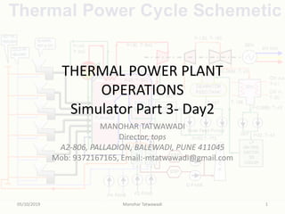
  • 1. THERMAL POWER PLANT OPERATIONS Simulator Part 3- Day2 MANOHAR TATWAWADI Director, tops A2-806, PALLADION, BALEWADI, PUNE 411045 Mob: 9372167165, Email:-mtatwawadi@gmail.com 05/10/2019 Manohar Tatwawadi 1
  • 2. PRDS CHARGING • Charge 16 ata header from other unit : • Open Aux PRDS Drains 10% from Field. • Put "PRDS CHARGE FROM OTHER UNIT" to 100 from field. • Observe pressure in 16 ata header on Boiler Feed Pump & PRDS' Panel. • Observe temp. in 16 ata header on 'Condensate Panel‘. • Same parameters also on Mimic page “Aux. PRDS System”. • Open auxiliary steam valve by putting "AUX PRDS TO EJS AS- 1" to ON position from Field page. • Open valve FW-83, FW-82, FW-77 (PRDS Spray) and AS- 51(PRDS Iso.) from Panel "Boiler feed pump and PRDS station" • Open AS-81 (Steam to Ejector) and AS-79 (Gland Steam Cooler)& GC-1 from Panel "Turbine Control/Lube oil Pump“. 05/10/2019 Manohar Tatwawadi 2
  • 4. CW SYSTEM • Open CW-1, CW-2,CW-3,CW-4,CW-5,CW-6,CW-7 and CW-8 from field page. • CW Pump-A Local/Remote/Panel on remote, Start the CW Pump A by switch on 'Condensate Panel‘ • Check Motor Current Graphics page 'Cooling Water system'. • NOTE: 1) If the pump is in local mode then, operate the pump from Field page. 2) Corresponding valves for CWP-B are also on same pages as CWP-A. • Start C.T lift pump from field page. 05/10/2019 Manohar Tatwawadi 4
  • 5. COOLING WATER SYSTEM 05/10/2019 Manohar Tatwawadi 5
  • 6. Deaerator Heating • Open Isolating Valves of AS-66,67,68 & 69 from Field page. • Open Isolating Valves of AS-72 & AS-73 from Field Page. • Open AS-72 to 30% from Panel and bring up the temperature of feed water in deaerator to around 85-90 degree C. (Watch Temp on Panel) • Open manually to 30% AS-57 (bypass of AS-58) & AS-65 from Panel. (16 ata auxiliary steam supply valve to deaerator.) • Put Both Valves on Auto with SP on 6 Kg/sqcm. • Start deaerating the incoming main condensate water into deaerator by opening deaerator steam pressure regulating valve. • Start feed water heating in deaerator by regulating steam valve AS-58 and bring up the temperature of feed water in deaerator to around 85-90 degree C. 05/10/2019 Manohar Tatwawadi 6
  • 7. FEED WATER SYSTEM 05/10/2019 Manohar Tatwawadi 7
  • 8. BOILER FEED PUMPS • For starting the boiler feed pump: • Put L/R/P switch to Remote for both Aux. Oil Pump & Boiler Feed Pump. • Ensure Feed pump auto control in Manual mode & Feed pump selection on DP mode from Panel-4 • Recirculation of Aux oil Pump and Warm up valve of BFP should be open. • BFP Scoop Position on Minimum. (30%) • BFP 1P/2P on 1 Pump. And BFP A/B/C/ selection on Manual • Give “ON” command to BFP A • Observe that the normalized current for BFP-A is 218 amps on panel-4.05/10/2019 Manohar Tatwawadi 8
  • 10. BOILER FEED PUMPS Observe the following : • Warm up-line valve and AOP closes on interlock. • Observe boiler feed pump suction flow (about 120t/hr) on trend page “Desk 4 – BFP Parameters” . • Observe that the boiler feed pump suction pressure is more than about 5.8 Kg/cm2 on panel-5. • Boiler feed pump discharge header pressure on panel-4 • The discharge valve indication on graphics "Feed Water System". • If ELP is running then put it OFF from field page 4. • Note the motor bearing temperatures along with oil pressure on IMV page no. 1 • Observe pressure at inlet of feed regulating station on panel-5 and open discharge valve FW-40 of BFP-A. • Start feeding water to boiler drum by opening low load regulating valve FW-26 in "manual mode" and increasing scoop tube position such that a flow of about 50 t/hr at minimum feed pump discharge pressure. 05/10/2019 Manohar Tatwawadi 10
  • 11. Establishing FEED WATER FLOW For establishing feed water flow to boiler • Again observe the following: • -BFP discharge header pressure • -Deaerator level • -Condenser hot well level • -FW26 control from panel-4 • -Control Master & pump scoop from panel-4. • -Observe feed water temperature and pressures. 05/10/2019 Manohar Tatwawadi 11
  • 12. Establishing FEED WATER FLOW… • -Keep a close watch a deaerator level and maintain at 3/4th of instrument scale by regulating DM make up valves DM-24 or DM-25. • -Keep a close watch on condenser hotwell and maintain at 3500 mm by regulating hot well level control valve MC-36 manually. • -Maintain deaerator water temperature around 90 degree C by deaerator feed tank heating valve AS-58. • -Observe drum level on panel-4 or "Feed Water System " graphics. • -Bring down pump scoop tube position such that feed pump discharge pressure is minimum (at least 5 Kg/cm2 more than low discharge pressure trip setting). 05/10/2019 Manohar Tatwawadi 12
  • 13. Establishing FEED WATER FLOW… • Keep on slowly raising deaerator temperature and pressure by deaerator steam regulating valve AS-58 and gradually observe the rise in pressure. Maintain the deaerator pressure at 6 kg/cm2 (7 ata). • Put Drum level control, scoop in Auto mode. • Make sure (3E,del p) switch position on del P position and (1E/3E) switch position on 1E position. • Make sure valve selection switch into Main position. • Put BFP A scoop & BFP B scoop controller into manual mode of operation. • Master scoop controller setpoint is on 50% settings.(CD-4) and in manual mode. • Increase output of master scoop controller till BFP a scoop setpoint matches with its measured variable. • Once the error becomes zero of BFP A scoop A then put BFP A scoop controller into Auto mode. • Adjust the master controller setpoint to match its measured variable and put into auto mode from CD-4. 05/10/2019 Manohar Tatwawadi 13
  • 14. CHARGING OF MAIN STEAM LINES • Main steam line to be charged by opening MS-11 & M-12 from field page no.11. • Check : Put interlock selector switch of boiler drum emergency drain valve in interlock mode from CD-4.OR Put Inching valve B-39 to 50%. • Open the following drain valves from Field page no. 11 • -MS line drain to 10% • -HPBP & LPBP line drains to 5%. • -HPT casing & rotor drains to 5%. • -IPT casing & rotor drains to 5%. • Continuous blow down is on Imf page No.10. • Keep a very close watch on boiler drum level and maintain it a normal value (0 mm of scale) if so required, by low load feed regulating valve FW-26. • -drum level on panel-4. • -Drum steam temp. on "Water & steam cycle" graphics. • -Drum metal temp. on bargraph group=3, page=7, variable=3. 05/10/2019 Manohar Tatwawadi 14
  • 15. Watching Drum Level & Flue Gas Temps. • Observe the gradual rise in flue gas temperatures at exit, at platen SH exit, at airheater exit, at economizer inlet, at airheaters inlet and at airheaters exit. (Mimic Page No.1) • Observe these parameters on trend page“Desk1–Flue gas Temperatures”. • Observe the gradual rise in air temperatures at air heaters exit on trend page “Desk 1 - Flue Gas Temperatures”. • Observe steam temperature on trend page “Desk4 – Drum Parameters”. • At about 2 kg/cm2 boiler drum pressure, close boiler drum vents from field page no.13 and superheater vents and at about 5 kg/cm2 of boiler drum pressure, throttle superheater drains. 05/10/2019 Manohar Tatwawadi 15
  • 16. Watching Drum Level & Flue Gas Temps 05/10/2019 Manohar Tatwawadi 16
  • 17. CONDENSER VACUUM BUILDUP • Check that non-return valves in CRH lines and their bypass valves (CR-3, CR-4) are closed from Panel • Close EV-1 & EV-2 from CD-5. • Open airvent to condensors CA1 & CA2 from field page no.14. • Open syphon filling valve MC-56 from field page no.9. • Close vacuum breaker valve from panel-7 • Observe turbine rotor’s differential expansions on panel or trend page no “Desk 7 – Turbine Expansions” . • Open the ejector drain valve from field page no.12.Put gland seal steam pressure controller valve(AS-81) with setpoint of .2kg into auto mode from Panel 7. from field page no.14 to charge the gland sealing system from panel-6. • Open the valve on air line to starting ejector CA-5 from panel-6 & observe graphics "Vacuum raising". • Start starting ejector by opening its steam supply valve AS-4 to 50% (Panel 7) . • Observe the condenser vacuum on panel 6. It will take approx.3 to 5min for vacuum to start.05/10/2019 Manohar Tatwawadi 17
  • 18. CR1, CR2, CR3 & CR4 NRVs MS & CRH NRVs 05/10/2019 Manohar Tatwawadi 18
  • 20. Vacuum Raising • Vacuum pulling has now started. • When the vacuum is around 30-35 mm of Hg.cl (about 0.04 kg/cm2) take gland cooler No. 1 steam ejector in service by opening steam supply valve to glands (AS-9,AS-10,AS-11,AS- 12,AS-13 & AS-14) from Field page no.14 such that, vacuum of about 450-500 mm is available at GC-1 ejector. • Close drains of Steam lines to starting ejector and to main ejectors and GSC-1 from Field page no. 12 • When the vacuum is around 50-60 mm of Hg.cl. (about .07 kg/cm2) admit steam to turbine gland seals by opening gland seal pressure regulating valve such that a pressure of about 0.15 kg/cm2 to 0.20 kg/cm2 is available in seal steam header. 05/10/2019 Manohar Tatwawadi 20
  • 21. GLANDS SEALING • Check that gland steam temperature is between 130-1500 C. • Put the control of turbine gland sealing steam pressure regulating valve AS-05 on `Auto‘ from Control Panel 7. • The rate of vacuum pulling would become faster when gland sealing steam is admitted. • Start both main ejectors by opening their steam supply valve (AS-2, AS-3) from Panel 7 to speed up the vacuum pulling rate. • Open CA-3 and CA-4 from field page no.14. • Open DM48,DM46,DM49,DM47 from field page no.12 on IC. • Observe Mimic "Air Ejection System" • When the vacuum in condenser is around 580 mm of Hg (about 0.76 kgcm-2) stop starting ejector first by closing its air line valve CA-5 and then closing its steam Supply valve AS-4. Vacuum continues to rise. 05/10/2019 Manohar Tatwawadi 21