How do the ais and virtual navigation buoys work
•Als PPTX, PDF herunterladen•
4 gefällt mir•2,065 views


Empfohlen
Empfohlen
Weitere ähnliche Inhalte
Was ist angesagt?
Was ist angesagt? (20)
Andere mochten auch
Andere mochten auch (20)
Ähnlich wie How do the ais and virtual navigation buoys work
Ähnlich wie How do the ais and virtual navigation buoys work (20)
Kürzlich hochgeladen
Kürzlich hochgeladen (20)
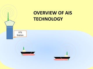
How do the ais and virtual navigation buoys work
- 2. Automatic Identification System does the transmission on two dedicated frequencies : Chanel A = Chanel B = These frequencies belong to the VHF Bandwidth. Thus, they conduct a line-of-sight transmission. Height of Antenna will become very much relevant in this case. Range of operation will be around 50 Nautical Miles, 20 NM being the average. VTS Station
- 3. VTS Station Each AIS equipment is designed to handle about 200 other equipment simultaneously, which are operating in its vicinity. Upon finding other transmissions, these AIS equipment have an electronic capability to form a loop between them and conduct a TIME SLICING in regard to transmission and reception.
- 4. VTS Station Each AIS equipment does transmission of its DATA for a specific ‘TIME SLICE’ and then switches into reception mode. Then, the second AIS does its transmission; and after that the third, and so on and so forth. This is TIME SLICING. During reception mode, the AIS equipment does ‘scanning mode’ reception on both Chanel A and Chanel B. The two channels are meant to provide for redundancy. TIME SLICING
- 5. VTS Station In case, some other passing-by ship reports to you that “possibly your ship’s AIS is not working” because they are not able to see your ship on their AIS, DO NOT get worried and jump into trouble-shooting. Such momentary ‘blanking’ are regular feature if the Time Slicing has accidently made two or more vessels to be in Transmission mode simultaneously. Give your AIS equipment some time, and they should be able to receive your vessel on their AIS. As a matter of fact, when there is more traffic in a given area, such ‘blanking’ will be more common.
- 6. USCG AIS Overview (source: Wikipedia)
- 7. Working of the bridge mounting part.
- 8. AIS receives feed from Autopilot and the GPS and transmits it to other vessels.
- 9. It receives data from other AIS , and does the mathematical processing to calculate the RANGE, BEARING, TCPA, CPA and other results. This is then put on display on the AIS screen, the RADAR and ECDIS The AIS paint and the RADAR paint of same target may not exactly match on RADAR screen.
- 10. If the “VIRTUAL” BUOYS are identified by the display device, such as the RADAR and/or ECDIS, then they are accordingly showed.
- 11. TYPE OF AIS DATA Fixed data 1) Vessel name 2) Call Sign, IMO Number, Port of Registry, MMSI 3) LOA, Beam , Height 4) Type of vessel Manually-fed data 1) Draught 2) Number of crew 3) Destination port 4) ETA 5) Navigational Status (at anchor/CBD/RAM/NUC/Fishing/Underway) 6) Safety/Urgency/ Distress/Routine message Dynamic data 1) Heading 2) Position 3) Speed 4) Course 5) Rate of Turn Calculated Data 1) Range 2) Bearing 3) TCPA 4) CPA
- 12. The VTS AIS unit does the transmission of the position of the “virtual” navigation buoys VTSSTATION Where are the ‘virtual’ navigation buoys located ? ‘Virtual’ Navigation Buoys have no connection with the bandwidth (S-Band, X-band) of the Radar in use. If your radar is not showing the virtual buoys , try after switching the feature “MAP OFF” to “MAP ON”. Otherwise, it is likely that your equipment software does not support virtual buoys.