Electro-Pneumatic Transducer for Process Control
•
0 gefällt mir•1,242 views

Converting from one signal type to another is a common challenge in process control. When the application calls for conversion from an electrical signal, current or voltage, to a pneumatic signal (pressure), this calls for an I/P or E/P transducer.

Empfohlen
Empfohlen
Weitere ähnliche Inhalte
Was ist angesagt?
Was ist angesagt? (19)
Ähnlich wie Electro-Pneumatic Transducer for Process Control
Ähnlich wie Electro-Pneumatic Transducer for Process Control (20)
Kürzlich hochgeladen
Kürzlich hochgeladen (20)
Electro-Pneumatic Transducer for Process Control
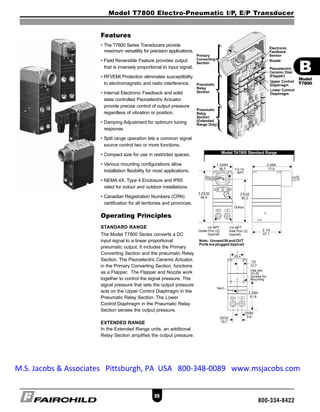
- 1. Model T7800 Electro-Pneumatic I/P, E/P Transducer 89 800-334-8422 Features • The T7800 Series Transducers provide maximum versatility for precision applications. • Field Reversible Feature provides output that is inversely proportional to input signal. • RFI/EMI Protection eliminates susceptibility to electromagnetic and radio interference. • Internal Electronic Feedback and solid state controlled Piezoelectric Actuator provide precise control of output pressure regardless of vibration or position. • Damping Adjustment for optimum tuning response. • Split range operation lets a common signal source control two or more functions. • Compact size for use in restricted spaces. • Various mounting configurations allow installation flexibility for most applications. • NEMA 4X, Type 4 Enclosure and IP65 rated for indoor and outdoor installations. • Canadian Registration Numbers (CRN) certification for all territories and provinces. Operating Principles STANDARD RANGE The Model T7800 Series converts a DC input signal to a linear proportional pneumatic output. It includes the Primary Converting Section and the pneumatic Relay Section. The Piezoelectric Ceramic Actuator, in the Primary Converting Section, functions as a Flapper. The Flapper and Nozzle work together to control the signal pressure. The signal pressure that sets the output pressure acts on the Upper Control Diaphragm in the Pneumatic Relay Section. The Lower Control Diaphragm in the Pneumatic Relay Section senses the output pressure. EXTENDED RANGE In the Extended Range units, an additional Relay Section amplifies the output pressure. Model TA7800 Standard Range B Model T7800 BTRANS65 quark 7:B Trans 65-110.qxd 9/1/2006 5:54 PM Page 89 M.S. Jacobs & Associates Pittsburgh, PA USA 800-348-0089 www.msjacobs.com
- 2. Model T7800 Electro-Pneumatic I/P, E/P Transducer 90 800-334-8422 Model TA7800 Extended Range Model TT7800 Extended Range Model TD7800 Extended Range Model TR7800 Extended Range Model TT7800 Standard Range Model TD7800 Standard Range Model TR7800 Standard Range Model TR7800 for use with TR Manifold Rack Kit. TR7800 unit same as TT7800 except terminal block is located on rear. Model TR7800 for use with TR Manifold Rack Kit. TR7800 unit same as TT7800 except terminal block is located on rear. B Model T7800 BTRANS65 quark 7:B Trans 65-110.qxd 9/1/2006 5:54 PM Page 90
- 3. Model T7800 Electro-Pneumatic I/P, E/P Transducer 91 800-334-8422 Standard Range Specifications OUTPUT RANGE psig [BAR] (kPa) 3-15 3-27 6-30 [0.2-1.0] [0.2-1.8] [0.4-2.0] (20-100) (20-180) (40-200) Input Range 4-20 mA DC, 0-10 VDC, 1-9 VDC Supply Pressure1 20-120 32-120 35-120 [1.5-8.0] [2.2-8.0] [2.4-8.0] (150-800) (220-800) (240-800) Minimum Span 5 10 10 [0.35] [0.7] [0.7] (35) (70) (70) Frequency Response -3 db @ 5 Hz per ISA S26.4.3.1 load configuration A. Accuracy (ISA S51.1) 0.25% Full Scale Guaranteed 0.15% Full Scale Typical Hysteresis (ISA S51.1) 0.1% Full Scale Deadband 0.02% Full Scale Repeatability (ISA S51.1) 0.1% Full Scale Position Effect No Measurable Effect Vibration Effect Less than +1% of Span under the following conditions: 5-15 Hz @ 0.8 inches constant displacement 15-500 Hz @ 10 Gs. Reverse Polarity Protection No damage occurs from reversal of normal supply current (4-20 mA) or from misapplication of up to 60 mA. RFI/EMI Effect Less than 0.5% of span @ 30 v /m class 3 Band ABC (20-1000 mHz) per SAMA PMC 33.1 1978 and less than 0.5% of Span @ 10 v /m level, to 2 GHz Band per EN 61000-4-3:1998 +A1 EMC Directive 89/336/EEC European Norms EN 61326 Supply Pressure Effect No Measurable Effect Temperature Effect [+0.5% +0.04% / o F Temperature Change] of Span typical Materials of Construction Body and Housing . . . . . . . . . . . . . . . . . . . . . . . . . .Chromate Treated Aluminum Orifice . . . . . . . . . . . . . . . . . . . . . . . . . . . . . . . . .Nickel Plated Brass & Sapphire Trim . . . . . . . . . . . . . . . . . . . . . . . . . . .Stainless Steel, Brass & Zinc Plated Steel Elastomers . . . . . . . . . . . . . . . . . . . . . . . . . . . . . . . . . . . . . . . . . . . . . . . . . .Nitrile Finish . . . . . . . . . . . . . . . . . . . . . . . . . . . . . . . . . . . . . . . . .Epoxy Powder Coating SET POINT psig [BAR] (kPa) 3 9 15 30 [0.2] [0.6] [1.0] [2.0] (20) (60) (100) (200) 1 Supply Pressure must be no less than 5 psig, [0.35 BAR], (35 kPa), above maximum output Maximum Air Consumption All Ranges 3.5 7.0 9.5 13.5 SCFH (.10 m3 /HR) (.20 m3 /HR) (.27 m3 /HR) (.38 m3 /HR) Flow Rate 2.5 (4.25 m3/ HR) @ 9.0 (15.3 m3 /HR) @ (SCFM) 25 psig, [1.7 BAR], 120 psig, [8.0 BAR], (170 kPa) supply & OR (800 kPa) supply & 9 psig, [0.6 BAR], 9 psig, [0.6 BAR], (60 kPa) Output (60 kPa) Output Temperature Range Operating -40o F to + 160o F (-40o C to + 71.2o C) Storage -40o F to + 180o F (-40o C to + 82.2o C) Span/Zero Adjustments Screwdriver adjustments located on front of unit Required Operating Voltages Two Wire Current Input 7.2 VDC @ 20 mA (4-20 mA signal) Supply Voltages Three Wire Voltage Input 7.2-30 VDC, less than 3 mA Signal Impedance Three Wire Voltage Input 10 Kilohms B Model T7800 BTRANS65 quark 7:B Trans 65-110.qxd 9/1/2006 5:54 PM Page 91
- 4. Model T7800 Electro-Pneumatic I/P, E/P Transducer 92 800-334-8422 Extended Range Specifications Input Range 4-20 mA DC, 0-10 VDC, 1-9 VDC Supply Pressure1 35-150 65-150 125-150 [2.4-10] [4.6-10] [8.8-10] (240-1000) (460-1000) (880-100) Minimum Span 12.5 25 50 [0.85] [1.5] [3.0] (85) (150) (300) Frequency Response -3 db @ 2 Hz per ISA S26.4.3.1 load configuration A. Accuracy (ISA S51.1) 0.25% Full Scale Guaranteed 0.15% Full Scale Typical Hysteresis (ISA S51.1) 0.25% Full Scale Deadband 0.02% Full Scale Repeatability (ISA S51.1) 0.1% Full Scale Position Effect 0.125% @ 90 0 & 0.25% @ 180 0 Vibration Effect Less than +1% of Span under the following conditions: 5-15 Hz @ 0.8 inches constant displacement 15-500 Hz @ 10 Gs. Reverse Polarity Protection No damage occurs from reversal of normal supply current (4-20 mA) or from misapplication of up to 60 mA. RFI/EMI Effect Less than 0.5% of span @ 30 v /m class 3 Band ABC (20-1000 mHz) per SAMA PMC 33.1 1978 and less than 0.5% of Span @ 10 v /m level, to 2 GHz Band per EN 61000-4-3:1998 +A1 EMC Directive 89/336/EEC European Norms EN 61326 Supply Pressure Effect < 0.1 psig change for 10 psig supply change Temperature Effect [+0.5% +0.06% / o F Temperature Change] of Span typical Materials of Construction Body and Housing . . . . . . . . . . . . . . . . . . . . . . . . . .Chromate Treated Aluminum Orifice . . . . . . . . . . . . . . . . . . . . . . . . . . . . . . . . .Nickel Plated Brass & Sapphire Trim . . . . . . . . . . . . . . . . . . . . . . . . . . .Stainless Steel, Brass & Zinc Plated Steel Elastomers . . . . . . . . . . . . . . . . . . . . . . . . . . . . . . . . . . . . . . . . . . . . . . . . . .Nitrile Finish . . . . . . . . . . . . . . . . . . . . . . . . . . . . . . . . . . . . . . . .Epoxy Powder Coating OUTPUT RANGE psig [BAR] (kPa) 0-30 0-60 0-120 [0-2.0] [0-4.0] [0-8.0] (0-200) (0-400) (0-800) SET POINT psig [BAR] (kPa) 0 15 30 60 120 [0] [1.0] [2.0] [4.0] [8.0] (0) (100) (200) (400) (800) Maximum Air Consumption 0-30 psig 3.1 7.8 11.8 SCFH (.09 m3 /HR) (.22 m3 /HR) (.33 m3 /HR) 0-60 psig 1.6 4.7 7.8 13.3 SCFH (0.4 m3 /HR) (.13 m3 /HR) (.22 m3 /HR) (.37 m3 /HR) 0-120 psig 0.5 3.8 7.6 15.1 SCFH (.01 m3 /HR) (.11 m3 /HR) (.21 m3 /HR) (.42 m3 /HR) Flow Rate (SCFM) 11.0 (18.7 m3 /HR) @ 150 psig, [10 BAR], (1000 kPa) supply & midscale output Temperature Range Operating -40o F to + 160o F, (-40o C to + 71.2o C) Storage -40o F to + 180o F, (-40o C to + 82.2o C) Span/Zero Adjustments Screwdriver adjustments located on front of unit Required Operating Voltages Two Wire Current Input 7.2 VDC @ 20 mA (4-20 mA signal) Supply Voltages Three Wire Voltage Input 7.2 - 30 VDC, less than 3 mA Signal Impedance Three Wire Voltage Input 10 Kilohms 1 Supply Pressure must be no less than 5 psig, [0.35 BAR], (35 kPa), above maximum output B Model T7800 BTRANS65 quark 7:B Trans 65-110.qxd 9/1/2006 5:54 PM Page 92
- 5. Model T7800 Electro-Pneumatic I/P, E/P Transducer 93 800-334-8422 Hazardous Area Specifications Intrinsically Safe (4-20 mA Only) Division 2 Factory Mutual TDFI7800, TAFI7800 TDFI7800, TAFI7800, (FM) Approvals Class I, Division 1, Groups C and D; TDFN7800, TAFN7800 Class II, Division 1, Groups E,F and G; Class I, Division 2, Groups A, B, C and D; Class III, Division 1, Fibers; Suitable for NEMA 4X Enclosure; Class II, Division 2, Groups F and G; Temperature Code T4, Tamb = -20 o C to 65 o C Class III, Division 2; NEMA 4X Enclosure; Non-Incendive 4-20 mA, voltage input units ; Temperature Code T4. TTFI7800, TRFI7800 TTFI7800, TRFI7800, Class I, Division 1, Groups C and D; TTFN7800, TRFN7800 Temperature Code T4, Tamb = -20 o C to 65 o C Class I, Division 2, Groups A, B, C and D; Non-Incendive 4-20 mA, voltage input units; Temperature Code T4. Canadian Standards TDCI7800, TACI7800 TDCI7800, TTCI7800, TRCI7800 Association (CSA) Class I, Division 1, Groups C and D; Class I, Division 2, Groups A, B, C and D; Approvals Class II, Division 1, Groups E, F and G; Rated 4-20 mA, 30 VDC maximum; Type 4 Enclosure; Temperature Code T6. Rated 4-20 mA, 30 VDC maximum; Temperature Code T6. Flame-Proof Intrinsically Safe TTCI7800, TRCI7800 TACI7800 Class I, Division 1, Groups C and D; Class I, Division 2, Groups A, B, C and D; Rated 4-20 mA, 30VDC maximum; Class II, Division 2, Groups E, F and G; Temperature Code T6. Type 4 Enclosure; Rated 4-20 mA, 30 VDC maximum; Temperature Code T6. ATEX Approvals TAEI7800, TDEI7800 EEx ia IIB, T4, Tamb = -20o C to 72o C II 1G (T4), II 1D (T85o C) IP65 Enclosure TTEI7800, TREI7800 EEx ia IIB, T4, Tamb = -20o C to 72o C II 1G (T4) Transducer Parameters Umax1= 28 V Pi3 = 0.7 W Imax2= 100 mA Ci4 = 0 Li5 = 0 1 Umax = Max. Voltage 3 Pi = Max. Power 2 Imax = Max. Current 4 Ci = Capacitance 5 Li = Inductance Approvals are valid when connected through a Shunt Zener Diode Safety Barrier meeting the following parametric requirements: System Type 1: Single Channel Polarized Rated: 28.5V Max. 300 Ohm Min. System Type 2: Dual Channel Polarized Rated 28.5V Max. 300 Ohm Min. and 10V Max. 50 Ohm Min. System Type 3: Dual Channel Polarized Rated: 28.5V Max. 300 Ohm Min. and 28V Diode return per channel Entity Parameters Vmax1 = 30 VDC Ci3 = O µ F Imax2 = 200 mA Li4 = O mH 1Vmax = Max. Voltage 3Ci = Capacitance 2Imax = Max. Current 4Li = Inductance Non-Incendive Field Wiring Parameters Vmax1 = 30 VDC Ci3 = O µ F Li4 = O mH 1Vmax = Max. Voltage 3Ci = Capacitance 4Li = Inductance B Model T7800 BTRANS65 quark 7:B Trans 65-110.qxd 9/1/2006 5:54 PM Page 93
- 6. Catalog Information Installation For installation instructions, refer to the Fairchild T7800 Standard Range Electro-Pneumatic Transducer Installation, Operation and Maintenance Instructions, IS-50T7800S and the Fairchild T7800 Extended Range Electro-Pneumatic Transducer Installation, Operation and Maintenance Instructions, IS-50T7800E. Optional manifolds are available to mount 3, 5, 10 or 15 transducers. An optional rack kit is available to mount 10 transducers in a standard 19” rack. For more information, see the Fairchild Manifold and Rack Kit, CS-4000MRKT. Catalog Number T 7800 Electrical Connections 1/2 NPT Conduit . . . . . . . . . . . . A Fitting with Pigtail DIN43650 Connection . . . . . . . . D Rack Mount . . . . . . . . . . . . . . . . R Terminal Block . . . . . . . . . . . . . . T Underwriting Group Canadian Standards . . . . . . . . . . . . . C ATEX . . . . . . . . . . . . . . . . . . . . . . . . . E Factory Mutual . . . . . . . . . . . . . . . . . . F None (leave blank) . . . . . . . . . . . . . . . Approval Class Intrinsically Safe1 . . . . . . . . . . . . . . . . . . . . I Non-Incendive (Division 2)2 . . . . . . . . . . . . N None (leave blank) . . . . . . . . . . . . . . . . . . . Input 4-20 mA . . . . . . . . . . . . . . . . . . . . . . . . . . . . . . . . . . . . . . . 4 1-5 VDC6 . . . . . . . . . . . . . . . . . . . . . . . . . . . . . . . . . . . . . . 5 0-5 VDC 6 . . . . . . . . . . . . . . . . . . . . . . . . . . . . . . . . . . . . . 7 1-9 VDC . . . . . . . . . . . . . . . . . . . . . . . . . . . . . . . . . . . . . . . 9 0-10 VDC . . . . . . . . . . . . . . . . . . . . . . . . . . . . . . . . . . . . . . 0 Output 3-15 psig 3 . . . . . . . . . . . . . . . . . . . . . . . . . . . . . . . . . . . . . . . . . 01 3-27 psig 3 . . . . . . . . . . . . . . . . . . . . . . . . . . . . . . . . . . . . . . . . . 02 6-30 psig 3 . . . . . . . . . . . . . . . . . . . . . . . . . . . . . . . . . . . . . . . . . 03 0-30 psig 4 . . . . . . . . . . . . . . . . . . . . . . . . . . . . . . . . . . . . . . . . . 04 0-60 psig 4 . . . . . . . . . . . . . . . . . . . . . . . . . . . . . . . . . . . . . . . . . 05 0-120 psig 4 . . . . . . . . . . . . . . . . . . . . . . . . . . . . . . . . . . . . . . . . 06 [0.2-1.0 BAR] 3 . . . . . . . . . . . . . . . . . . . . . . . . . . . . . . . . . . . . . . 11 [0.2-1.8 BAR] 3 . . . . . . . . . . . . . . . . . . . . . . . . . . . . . . . . . . . . . . 12 [0.4-2.0 BAR] 3 . . . . . . . . . . . . . . . . . . . . . . . . . . . . . . . . . . . . . . 13 [0-2.0 BAR] 4 . . . . . . . . . . . . . . . . . . . . . . . . . . . . . . . . . . . . . . . 14 [0-4.0 BAR] 4 . . . . . . . . . . . . . . . . . . . . . . . . . . . . . . . . . . . . . . . 15 [0-8.0 BAR] 4 . . . . . . . . . . . . . . . . . . . . . . . . . . . . . . . . . . . . . . . 16 (20-100 kPa) 3 . . . . . . . . . . . . . . . . . . . . . . . . . . . . . . . . . . . . . . 21 (20-180 kPa) 3 . . . . . . . . . . . . . . . . . . . . . . . . . . . . . . . . . . . . . . 22 (40-200 kPa) 3 . . . . . . . . . . . . . . . . . . . . . . . . . . . . . . . . . . . . . . 23 (0-200 kPa) 4 . . . . . . . . . . . . . . . . . . . . . . . . . . . . . . . . . . . . . . . 24 (0-400 kPa) 4 . . . . . . . . . . . . . . . . . . . . . . . . . . . . . . . . . . . . . . 25 (0-800 kPa) 4 . . . . . . . . . . . . . . . . . . . . . . . . . . . . . . . . . . . . . . . 26 Options BSPT Thread 5 . . . . . . . . . . . . . . . . . . . . . . . . . . . . . . . . . . . . . . . . . . U 1 Intrinsically Safe Approval includes Non-Incendive (Division 2), available on 4-20 mA units only. 2 Non-Incendive (Division 2) approval on FM voltage input units only 3 Standard Range 4 Extended Range 5 Available on all units EXCEPT Factory Mutual and Canadian Standards Underwriting Group units. 6 Limited Availability Mounting Kits Mounting Bracket: 16799-1 Mounting Bracket: 16893 Mounting Bracket: 19254-1 Model T7800 Transducer Kits & Accessories Mounting Bracket Kits ..........16799-1 (included with unit) 16893 (included with unit) 19254-1 (sold separately) Model T7800 Electro-Pneumatic I/P, E/P Transducer 94 800-334-8422 BB Model T7800 BTRANS65 quark 7:B Trans 65-110.qxd 9/1/2006 5:54 PM Page 94