1. Lowfields Road
Leeds, LS12 6BS, UK
Tel: +44 (0) 113 244 5225
Fax: +44 (0) 113 244 5226
info@microdat.co.uk
www.microdat.co.uk
Microdat is a trading name of Microdat.co.uk Limited. Microdat.co.uk Limited is a company registered in England and Wales with company number 4299819.
Registered Office: Microdat.co.uk Limited, Lowfields Road, Leeds, LS12 6BS. Telephone +44 (0) 113 244 5225, Fax: +44 (0) 113 244 5226.
Website: www.microdat.co.uk , Email: info@microdat.co.uk , VAT Number: 780 5449 11.
Cleaning In Place (CIP) System Design Manual
A cleaning In Place (CIP) system is designed to clean a liquid processing plant without the need to
strip it down into component parts, and manually clean with scourers etc.
The benefit of a CIP system, is that once set-up, it will clean the plant equipment, time and again,
while the operators get on with other duties, i.e. it is supposed to be labour saving.
It is possible to have a very simple manual CIP system, but here there is little benefit of labour
saving.
A CIP system has to be designed properly to match the plant being cleaned.
The primary function is soil removal, but also to sanitise the process equipment.
This document is designed as an outline guide for correct CIP system design and selection.
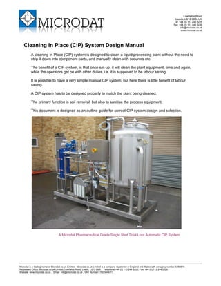
A Microdat Pharmaceutical Grade Single Shot Total Loss Automatic CIP System
2. Microdat CIP System Design Manual Page 2 of 9
Tank Cleaning Application In A Brewhouse
1 SOIL REMOVAL
For effective cleaning we need to consider :
Temperature + Scouring Action + Time + Detergent Type & Concentration
If any of these aspects are not sufficient, then cleaning will be compromised.
1.1 TEMPERATURE
Most detergents become more effective when hot, and in a dairy, where the soiling is fat
based, temperature is very important. Use of hot (80°C) CIP will also effectively pasteurise
the plant, killing off any possibility of infections.
However, given the additional energy requirements, Hot CIP has largely been replaced in
small breweries, with the use of cold detergents and chemical terminal sanitisers in the final
rinse, except for the brewhouse, where hot CIP assists in the removal of sugars.
1.2 SCOURING ACTION - PIPES
A scouring action is required to assist the detergent to remove the soiling in pipework
systems. When fluid passes down a pipe, contact with the tube internal wall creates friction.
At low velocity this friction has little effect, and the flow is smooth and laminar. However, at
higher velocity, the flow becomes very turbulent, and this turbulence creates an internal
scouring action.
1.3 SCOURING ACTION - TANKS
In tank cleaning, scouring action
can be provided by a modern
CIP tank cleaning head.
These devices create jets of
fluid, like a high-pressure hose,
cutting into and removing
soiling.
With a cleaning head, there is
some reliance on a soaking
action, and also more reliance
on the action of the detergent.
More detail about cleaning
heads is provided the CIP
system design section.
MASH TUN
LIGHT
2"OD
Vent
2"OD
3200 Kg
WORM &
GEAR
STEELES
MASHER
SA3353
9600 kg/hr
2"OD
SP
2"OD
1"OD
SA3354
GRAIN
DISCHARGE
1"OD
P107
3. Microdat CIP System Design Manual Page 3 of 9
Caustic Soda For A Brewery CIP System
1.4 TIME CONSIDERATIONS
The minimum time for a CIP cycle is dependent upon all the other factors; correct scouring
action, detergent type & concentration, and temperature.
If one part of the equation is not ideal, then extending the time can sometimes compensate.
Too little time, and the soiling will not be removed, but there is little benefit in massively over
extending cycle times.
1.5 DETERGENT TYPES & CONCENTRATIONS
The correct choice of detergents contributes strongly to the effectiveness of CIP.
The standard in small to medium breweries is Caustic Soda (Sodium Hydroxide), which is
cheap and readily available.
CIP detergents also contain additional active components, referred to as sequestrants, and
surfactants, which are designed to keep soiling in suspension once removed from the
surfaces, and to reduce foaming and to give other beneficial properties.
Other chemicals are sometimes added by the supplier, to create specific cocktails providing
benefits to plant problems, such as beer-stone removal.
In some brewery applications, with high CO2 atmospheres, an acid based detergent will be
recommended. This is because Sodium Hydroxide reacts with Carbon Dioxide, and in
closed vessels this can lead, in extreme cases, to tank collapse. In atmospheric tanks, this
reaction is less of a concern, except that the effectiveness of the caustic solution is steadily
neutralised by CO2, and as a by-product, the reaction generates Sodium Carbonate. This
degeneration is difficult to detect in an automatic CIP system, which uses conductivity
instrumentation to control the caustic concentration. In any case in a brewery application,
the caustic should be regularly checked and refreshed as necessary
Once the correct chemical is selected, the correct
concentration must be used. Generally, the supplier’s
guidelines should be followed, but given that their business
is built on selling chemicals in bulk, their recommendations
should be checked with general industry practices.
Use of strongly chlorinated products, and strong
concentrations of sodium hypochlorite should be avoided if
possible, as they are corrosive to stainless steel. Heat
exchangers are particularly vulnerable, due to their very thin
plates. When used hot, these products can contribute to the
causes of stress corrosion cracking in stainless steel tanks.
Highly chlorinated products should be rinsed from the
system, using either hot water, UV treated water or using a
further terminal sanitiser.
Warning: Detergents should never be mixed, either in dilute or concentrate form,
unless specifically directed by your supplier as violent and potentially deadly
reactions can occur.
4. Microdat CIP System Design Manual Page 4 of 9
2 TERMINAL SANITISERS
Terminal Sanitisers are used at the end of the final rinse to kill any residual or introduced micro-
organisms in the plant following the final rinse. They are recirculated at CIP velocities and through
tank cleaning heads, and have a defined minimum contact time.
The most commonly used terminal sanitiser is Peracetic Acid (also known as peroxyacetic acid)
(PAA).
Some sanitisers, such as Sodium Hypochlorite and Hydrogen Peroxide are highly corrosive to
stainless steel, and so should be avoided.
PAA is favoured because it breaks down in food to safe and environmentally friendly residues
(water, acetic acid, low strength hydrogen peroxide and oxygen). It is left to drain down following
CIP without any final rinsing.
As with all chemicals, there are hazards.
PAA is a very strong oxidiser, and is very harmful in contact with the skin or eyes, especially in neat
form. It should never be handled manually without adequate PPE.
PAA can present a fire or explosion hazard, because when it breaks down, it produces oxygen.
If PAA is left in a closed system, it will slowly build in pressure as the chemical denatures. It is
important to leave tanks and pipework to drain following sanitising.
PAA is not compatible with natural rubbers, so valve and pipe seals etc. have to be carefully
selected, and some dosing systems, which use rubber components are not suitable.
Finished beer can be affected by residual PAA in pipework systems, due to oxygen generation.
Where this is critical, for instance beer for bottling, hot water can be used to purge PAA from the
pipework prior to the beer transfer. This is not considered a problem in cask beer production.
Microdat’s Standard Low Cost Twin Tank Automatic CIP System
5. Microdat CIP System Design Manual Page 5 of 9
3 PLANT DESIGN FOR CIP
For effective CIP, the production plant must be designed correctly. Hygienic components, designed
for CIP must be used, with no crevices or dead spots. Pipework systems must be designed with no
dead legs, and diameters of pipe should be consistent to allow correct CIP velocities in all sections
of the pipework route. There should be no restrictions to flow rate in the system (i.e. positive
displacement pumps should have a CIP bypass facility).
4 CIP PLANT CONFIGUARTIONS
According to the conditions, capital availability, and preferences of the brewer, a number of systems
are available.
4.1 SINGLE TANK CAUSTIC STORAGE SYSTEM
A single tank CIP system can be used to store and recirculate caustic in a closed loop.
Pre rinse and final rinses in this system, are fed directly from the mains, and this is often
difficult to accommodate, given the flowrate required for turbulent flow.
Water authority bylaws also restrict direct connection of CIP systems, to their water mains
without a break tank.
4.2 SINGLE TANK TOTAL LOSS SYSTEMS
This system uses a single tank for all rinses, which are drained at the end of each rinse
cycle. These systems have low capital costs, but very high running costs, and are only really
used in critical non-contamination applications like in the pharmaceutical industry.
Typical Microdat Total Loss System
6. Microdat CIP System Design Manual Page 6 of 9
4.3 MULTI-TANK SYSTEMS
Rinse Water Break Tank
Used either where the flowrate of mains water in the brewery is insufficient to provide
turbulent flow in the pipework, or when there is no other water break tank in the facility. The
water break tank is used to store enough fresh water for at least one CIP cycle.
Recovered Rinse Water Tank
After a detergent cycle, the fresh water used as a post rinse and the terminal sanitisers are
collected and re-used as the pre-rinse for the next CIP cycle.
This saves both water usage and effluent costs.
Detergent Tanks
A tank is used to store a batch of dilute detergent, which is recirculated around the plant and
returned back to the detergent tank again.
Some larger breweries may use both caustic and acid based detergents in which case the
CIP set may have two detergent tanks.
Use of a detergent tank saves costs of chemicals when compared to single tank total loss
systems.
Typical Microdat Rinse Recovery System
7. Microdat CIP System Design Manual Page 7 of 9
5 CIP PLANT DESIGN CONSIDERATIONS
5.1 TANK CLEANING HEADS
Modern tank cleaning heads are
designed to utilise a jet of fluid. This
provides a good scouring action on
the tank walls. There are other
cleaning, heads usually referred to as
spray balls, which provide a lower
pressure of spray, which then relies
more on temperature, detergent
strength and time, to achieve
consistent cleaning of the vessel
(rather than scouring action).
The choice of cleaning head is often a combination of price vs performance. In a small
diameter vessel, the choice of low cost cleaning heads is greater than in high diameter
vessels, where more complex specific designs are required to provide the right jetting action.
There are other factors to consider in selecting a cleaning head. Tank cleaning CIP flow rate
is sometimes matched to the fluid velocity required for cleaning the tank outlet, which is pipe-
size dependant. More usually however, best practice is to use the supply and scavenge
pump control, to produce regular cycling of pooling and scavenging in the tank, to provide the
outlet pipe cleaning.
An important aspect in designing the CIP supply pump system, is to consider the flow and
pressure performance curve of the pump, and to match it to the requirements of the cleaning
head. If the CIP fluid is presented at too high pressure (at the stated flowrate), then the CIP
fluid may atomise into a spray cloud, and conversely, at too low pressure, the intended jet
would too weak to be effective.
A cheap cleaning head will provide little benefit, in terms of reducing cycle times, and energy
and effluent costs. However complex cleaning heads from mainstream suppliers for large
vessels can cost upwards of £1000, and are not usually required in smaller breweries.
It is important to get the balance right.
5.2 CIP SUPPLY PUMP
A pipeline clean requires : Low Pressure + High Flowrate.
A tank cleaning CIP head requires: High Pressure + Low Flowrate.
The CIP supply pump therefore ideally has a variable speed drive or inverter to provide
various set-points to suit the plant. The variable speed drive can also be used if cleaning
more than one pipe-size, to generate the correct flowrate.
It is sometimes possible to match the cleaning head flow pressure requirements well with the
pipe cleaning requirements, so removing the need for variable speed, but this is only really in
simple applications.
A Selection of Spray Balls & Rotary Cleaning Heads
8. Microdat CIP System Design Manual Page 8 of 9
5.3 CIP SCAVENGE PUMPS
When cleaning tanks with a CIP system, a scavenging pump is required to return CIP to the
CIP set.
It is important for tank cleaning, that the scavenging pump is capable of pumping a mixture of
air and water, otherwise it will easily become air locked. This necessitates an expensive
style of pump, either a liquid ring pump (which is best), or a self-priming pump.
The scavenge pump control is usually started and stopped in conjunction with the CIP
supply pump control, to create a pool of CIP fluid in the vessel. This is then pumped away at
high velocity to match the tank outlet pipework, for effective turbulent flow, thus cleaning the
outlet pipe.
5.4 CIP VELOCITY
As explained earlier, it is critical to control flowrates in pipes to provide turbulent flow and
therefore provide a scouring action.
Turbulent flow is generated at flow velocities above 1.5m/second. It is recognised that there
is no benefit in increasing the velocity past 2.1m/second, as diminishing benefits are realised
and increases in energy usage and effluent are the only result.
Flowrate Table For Different Pipe Sizes.
Pipesize Min CIP Velocity
(1.5m/sec)
Ideal CIP Velocity
(1.8m/sec)
Max CIP Velocity
(2.1m/sec)
1.0” 2.8 m3
/hr. 3.3 m3
/hr. 3.9 m3
/hr.
1.5” 6.3 m3
/hr. 7.5 m3
/hr. 8.7 m3
/hr.
2.0” 11.1 m3
/hr. 13.3 m3
/hr. 15.6 m3
/hr.
2.5” 17.4 m3
/hr. 20.8 m3
/hr. 24.3 m3
/hr.
3.0” 25.0 m3
/hr. 30.0 m3
/hr. 35.0 m3
/hr.
5.5 INSTRUMENTATION
Depending upon the depth of automation, instruments may include tank level switches or
level transmitters, return flow switch or flow meter, supply flow switch or meter, CIP pump
pressure transmitter, temperature transmitters, conductivity meter for caustic dosing control
and return rinse water routing.
5.6 AUTOVALVES
Pneumatic valves are used for automatic systems to route the different rinse fluids from and
to the tanks and to drain.