8377877756 Full Enjoy @24/7 Call Girls in Nirman Vihar Delhi NCR
CEP2005_OnionModel.pdf
1. Process Simulation
CEP www.cepmagazine.org October 2005 25
T
he design of a chemical process involves synthesis and
analysis. Process synthesis is the overall development of
a process flowsheet by combining individual steps
(equipment and operating conditions) into an optimal arrange-
ment. Process analysis breaks down the flowsheet to evaluate
the performance of each individual element as well as how the
overall process would perform, typically by a process simulator.
Process analysis is often performed after the synthesis task
has been completed. The major disadvantage of this approach
is that if the flowsheet is found to be infeasible during the
analysis stage, the synthesis task must be repeated before the
next analysis step can take place. This rework can be avoided
if the flowsheet is synthesized with the use of a process syn-
thesis model and simulation tool.
This article shows how these tools can be used hand-in-
hand to generate a reasonably good process flowsheet. This is
particularly useful for evaluating a new process path or gener-
ating alternatives for new process development.
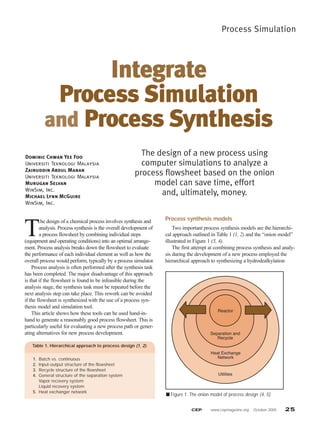
Process synthesis models
Two important process synthesis models are the hierarchi-
cal approach outlined in Table 1 (1, 2) and the “onion model”
illustrated in Figure 1 (3, 4).
The first attempt at combining process synthesis and analy-
sis during the development of a new process employed the
hierarchical approach to synthesizing a hydrodealkylation
Integrate
Process Simulation
and Process Synthesis
Dominic Chwan Yee Foo
Universiti Teknologi Malaysia
Zainuddin Abdul Manan
Universiti Teknologi Malaysia
Murugan Selvan
WinSim, Inc.
Michael Lynn McGuire
WinSim, Inc.
The design of a new process using
computer simulations to analyze a
process flowsheet based on the onion
model can save time, effort
and, ultimately, money.
Table 1. Hierarchical approach to process design (1, 2).
1. Batch vs. continuous
2. Input-output structure of the flowsheet
3. Recycle structure of the flowsheet
4. General structure of the separation system
Vapor recovery system
Liquid recovery system
5. Heat exchanger network
■ Figure 1. The onion model of process design (4, 5).
Reactor
Separation and
Recycle
Heat Exchange
Network
Utilities
2. 26 www.cepmagazine.org October 2005 CEP
process in an equation-based process simulator (5). The main
drawback of this approach is that equation-based process sim-
ulators often require much time to write the software code
before the simulation can be performed. Modular-based
process simulators provide an effective means of handling the
process simulation tasks.
The onion model is an alternative way to present the hier-
archical approach to process design. Process design begins at
the center of the onion, with the reactor, and proceeds out-
ward. The reactor design influences the separation and recycle
structures (the second layer of the onion), which are designed
next. The reactor, recycle and separator structures dictate the
overall heat-recovery requirements, so the heat-recovery net-
work design comes next. Finally, the process utility systems
are designed to provide additional heating and cooling
requirements that cannot be satisfied through heat recovery.
This model emphasizes the sequential and hierarchical nature
of process flowsheet synthesis.
However, the onion model of process synthesis requires
the use of a process analysis tool as well. Synthesis decisions
made at each layer of the onion model may require a detailed
analysis — and this is the role of a process simulator.
Simulation is performed at each individual layer after new
units are added or new decisions are made. This ensures that a
feasible process flowsheet (in terms of mass and energy bal-
ances, operating conditions, etc.) is developed at each layer of
the onion. Optimization may also be performed on each
newly added unit to identify the optimum design variables
(hardware optimization) as well as its operating conditions
(parametric optimization).
The heart of the process — the reactor
Synthesis of a new process flowsheet should start at the
heart of the chemical process, i.e., the reactor system. This is
where raw materials are converted into valuable products.
When synthesizing and modeling a reactor system, the
process designer must consider the following questions:
• What is the right reactor model (continuous stirred-
tank reactor, plug-flow reactor, etc.), and what are its
operating conditions (isothermal, adiabatic, constant outlet
temperature, vacuum, etc.)?
• How should the product conversion and yield be
determined?
• Is a catalyst needed in the reactor system modeling?
Answers to the first two questions can be found in the
literature for a wide variety of reactions. When multiple sets
of operating conditions exist, process simulators can serve
as a tool for comparing the viable options. Simulation pro-
vides more information than the available literature in terms
of heating or cooling requirements, operating conditions,
and so on.
Catalyst modeling can usually be omitted from reactor
modeling, provided mass and energy balances are the only
targets of the simulation. However, if a catalyst used in the
process involves a phase change, including it in the analysis
will result in a more complete analysis of the reactor system’s
heating requirements.
Layer 2 — separation and recycle
After the reactor system synthesis and modeling is finished,
the focus shifts to the second layer of the onion model. Products
and any byproducts formed in the reactor need to be separated
from unconverted reactant for further purification, while the
unconverted raw material is recycled back to the reactor.
Separation system. Separation systems can be broadly
classified as liquid or vapor separations. When a reactor
effluent contains a mixture of liquid and vapor, a phase sepa-
rator such as a flash column is normally used to separate the
phases before they enter into their respective separation sys-
tems (Figure 2).
If a flash column with two degrees of freedom is
employed, the designer must specify two process variables for
the modeling. For simplicity, temperature and pressure (or
pressure drop) are frequently used.
Vapor separation systems include condensers, flash tanks,
absorbers, adsorbers, and gas separation membranes. These
unit operations are normally used to purify a vapor recycle
stream before it re-enters the process. A purge stream is
always employed to avoid undesired contaminant build-up.
Liquid separation systems include distillation (including
extractive distillation), solvent extraction, stripping, filtration
(including membrane separation), centrifugation, and so on.
The selection of the appropriate separation process has been
discussed extensively in design textbooks (e.g., 2, 6, 7) and
will not be covered here. Because distillation is so widely used,
distillation column modeling will be discussed in detail here.
Process Simulation
■ Figure 2. The overall separation scheme consists of vapor,
liquid and flash separations (1, 2).
Feed
Feed
Reactor
System
Liquid
Separation
System
Flash
Vapor
Separation
System
Purge
Products
Byproducts
3. CEP www.cepmagazine.org October 2005 27
Specifications required for the modeling of a distilla-
tion column typically include:
• number of theoretical trays. A good initial estimate can
often be obtained using short-cut methods such as the
Fenske equation (2) or a simplified separation model avail-
able in a simulator.
• column top and bottom temperatures. Estimates obtained
from short-cut modeling will often lead to faster convergence
during column simulation.
• column pressure. Either the top or bottom column pres-
sure is normally set by the column designer, or a column pres-
sure drop is specified based on the column top pressure.
• feed tray location(s). Feed tray locations are selected
based on such considerations as energy conservation (both
feed stream and feed tray have the same temperature) and
required product purity (a higher feed tray location might
affect the top product stream composition), among others.
• estimated product flowrates. Some simulators require an
estimate of the top and bottom product flowrates for the ini-
tialization of the column convergence calculations. (This value
will be different from the desired product flowrate specified as
the convergence criterion during the simulation.)
Most column modeling for non-complex mixture separa-
tions will converge without much difficulty. Occasionally, col-
umn modeling fails to converge. The following steps can be
taken to aid the convergence of a column:
1. Evaluate thermodynamic choices, especially K-values.
2. Generate initial guesses using a short-cut method.
3. Look for unachievable and impossible specifications (for
example, reboiler duty that vaporizes the entire feed, product
specifications that violate the column material balance, etc.).
4. Simplify choices for heat and material balance specifica-
tions.Avoid complex approaches that set specifications (e.g.,
component recoveries, reflux ratios, and reboiler ratios) for the
top and bottom streams that might be in conflict with each other.
Recycle system. Recycling is the tricky part of flowsheet
modeling. A good start (for beginners) in modeling a recycle
loop is to use the concept of a “tear stream” (8).
As shown in Figure 3, the recycle stream after unit F is
considered as two separate tear streams, R1 and R2. After unit
A and B are solved, the simulation moves to unit C. Some ini-
tial guesses for the tear stream R1 are made so the simulation
can proceed to units D, E and F. After unit F converges, the
resulting flowrate of stream R2 is compared to the initial guess
for R1. If the values agree to within a specified tolerance, it is
likely that the simulation model has converged. The calculated
value of R2 is then used in place of R1 in unit C and the simu-
lation is rerun.
If tear streams R1 and R2 do not agree to within the speci-
fied tolerance, the initial guess for R1 is revised and the simula-
tion is rerun (without connecting the recycle stream to unit C).
Previous CEP articles (9, 10) provided some good sugges-
tions to aid the recycle simulation. Here are a few more:
• Maintaining product specification remains the highest pri-
ority of the process.
• Take note of the changes in feed temperature and pressure.
• Beware of the accumulation of unwanted pollutants in the
process loop. A purge stream is important to ensure that the
recycle system does not trap unwanted material.
An additional tip to speed up the recycling loop conver-
gence is to increase the convergence tolerance at the initial
stage of the recycling simulation. When the flowsheet has
converged at this larger tolerance, the convergence tolerance is
then reduced. This will enable the flowsheet to converge faster
than if a tight convergence tolerance is specified at the initial
stage. One can also explore various optimization options with-
in the recycle system associated with the reaction and separa-
tion systems of the process (4).
Layer 3 — the heat exchange network
The process heating and cooling loads are determined after
the process structure within the two inner layers of the onion
model (i.e., the reactor, and separation and recycle systems)
has been finalized. It is now time to design and model the heat
exchange network (HEN). This is usually done using the well-
established tool of process integration, which divides the HEN
design procedure into two stages — utility targeting, and net-
work design. The details of this are beyond the scope of this
article, and readers are referred to Refs. 2, 3, 6 and 7.
After a preliminary network has been synthesized, the
process flowsheet will normally undergo a complete re-simu-
lation to verify the energy balances. Often, more recycle loops
will be involved as the process streams that were used for
process-to-process heat exchange are now interconnected. The
tear stream concept is also useful at this stage.
Layer 4 — utilities
After the heat exchange network has been synthesized, the
outermost layer of the onion model — i.e., the utility system
— is addressed. The selection of hot and cold utilities is
another well-established application of process integration (3,
■ Figure 3. The tear stream concept is used in recycle simulation (8).
A B C D E F
Unit Operation
in Simulator
R1
R2
Recycle Stream
Tear Recycle Stream
/ /
4. 28 www.cepmagazine.org October 2005 CEP
6, 7). Other options to be explored include the placement of
the heat pump and heat engine.
A process simulator is a useful tool to evaluate the selected
utilities. Often, a simulated process flowsheet provides a good
picture of how well a process is likely to perform after start-up.
Example: production of n-octane
The onion model synthesis and simulation technique will
be used to develop a process flowsheet for n-octane (C8H18)
production from ethylene (C2H4) and i-butane (C4H10).
Component flowrates (with some impurities) and stream spec-
ifications for the fresh feed are given in Table 2.
DESIGN II for Windows is used as the simulation tool. This
modular-based software has 886 components in its databank and
uses the sequential-modular approach to perform its calculations.
Various thermodynamic models can be loaded into the simulation.
Flowsheet development. Ethylene and i-butane react isother-
mally in a stoichiometric isothermal reactor at 93ºC to produce
n-octane. The key component that limits the reaction conversion
is taken as ethylene, with an overall conversion of 98%. The pres-
sure drop across the reactor is specified at 5 psi. The reaction is:
2C2H4 + C4H10 → C8H18
After the reactor simulation has converged, the synthesis and
analysis task focuses on the separation and recycle systems. A
flash column is added to the reactor effluent to separate the
unconverted raw materials from the desired product. Apressure
drop of 2 psi is introduced, while the operating temperature is
maintained the same as that of the reactor. The more-volatile
compounds (ethylene, i-butane, and other impurities) are
flashed to the top product stream together with a small portion
of the heavier product, n-octane, while the remaining n-octane
leaves at the bottom. An additional separation unit is needed to
recover the n-octane product from the top stream.
Distillation is then added to the flash column’s top product
stream to recover n-octane. The short-cut design method deter-
mines that this column has 10 theoretical trays and operates at
15 psia. The remaining n-octane component is recovered at the
column bottom while the volatile components leave from the
column top. Since the n-octane separation involves both the
flash and distillation models, parametric optimization is per-
formed to determine the best combination of operating parame-
ters in these models for optimal n-octane recovery.
The unconverted raw material leaving at the distillation top
stream is now pure enough for recycle. A purge stream is
added before the stream is recompressed, reheated and sent
back to the reactor. The tear stream concept is utilized to facil-
itate convergence of the recycle stream. Figure 4 is a prelimi-
nary process flowsheet based on the synthesis and simulation
conducted this far.
Process Simulation
Table 2. Molar feed flowrate for each component
in the production of n-octane (example).
Flowrate,
Components kg-mol/h Specification
Nitrogen, N2 0.1
Ethylene, C2H4 20 T = 30ºC
n-Butane, C4H10 0.5 P = 20 psia
i-Butane, C4H10 10
■ Figure 4. The preliminary flowsheet for the production of
n-octane after completion of onion model layers 1 and 2.
Fresh
Feed
Heater
Mixer
Reactor
Flash
n-Octane
n-Octane
Purge
Unconverted
Reactant Chiller
Compressor
Distillation
■ Figure 5. The complete flowsheet with a heat-integrated
distillation column.
Unconverted
Reactant
Mixer
Heater
Reactor
Compressor
Flash
Distillation
n-Octane
n-Octane
Fresh
Feed
Purge
30°C
73.57°C
101.4°C
82.23°C
93.3°C
93.3°C
■ Figure 6. The complete flowsheet with a stand-alone
distillation column.
Unconverted
Reactant
Mixer
Heater
Reactor
Compressor
Flash
Distillation
n-Octane
n-Octane
Purge
101.4°C
93.3°C
Fresh Feed 30°C
93.3°C
91.4°C
5. CEP www.cepmagazine.org October 2005 29
Next, the design of the heat exchange network and utility
system will be handled simultaneously. Stream enthalpy data
needed for the analysis is extracted from the converged flow-
sheet in Figure 4. After the HEN is designed using process
integration techniques, the simulation is re-run to verify the
overall mass and energy balances for the heat-integrated flow-
sheet (Figure 5). The tear stream concept is utilized at this
stage since the integrated process streams are considered as
recycle streams in the sequential modular approach (e.g., the
raw material recycle stream in Figure 5).
Alternatively, if distillation is not preferred for the heat
integration scheme because of controllability reasons, the
alternative flowsheet is that shown in Figure 6. This gives the
process designer another option for comparison (e.g., energy,
controllability, complexity, etc) during process development.
Closing thoughts
The final advice to simulation users is this: Check the sim-
ulation results and don’t accept that everything is as it appears.
The garbage-in, garbage-out (GIGO) principle applies to all
computer models (11). They are not smart enough to identify
wrong information provided by the user, and in turn, they pro-
duce poor results without the user’s awareness (12, 13).
Also, the simulator’s physical property system is not a
black box. Rather, it is a well-developed set of rules, correla-
tions and relationships that can execute complex calculations
very quickly without violating first principles.
Simulation does not replace that most useful of all tools of
a chemical engineer — common sense (14). Always use engi-
neering judgment to evaluate simulation errors or suspicious
results to find their source. Computing efforts are nothing but
speedy number crunchers that have logical clues, fingerprints
and reasons. It is just a matter of tracking them down with less
time using fundamentally sound principles.
D
DO
OM
MI
IN
NI
IC
C C
CH
HW
WA
AN
N Y
YE
EE
E F
FO
OO
O is a research associate at the Chemical Engineering
Pilot Plant (CEPP) at the Universiti Teknologi Malaysia (Phone: +60-7-553-1662;
Fax: +60-7-556-9706; E-mail: cyfoo@cepp.utm.my). His main research interests
include process synthesis and design as well as process integration via pinch
analysis. He has extensive training in using process simulators for process
modeling and debottlenecking of continuous and batch processes. He obtained
his BEng and MEng degrees in chemical engineering from the Universiti
Teknologi Malaysia. He is a member of the Institute of Chemical Engineers
Malaysia (IChEM) and the Institution of Chemical Engineers (IChemE).
Z
ZA
AI
IN
NU
UD
DD
DI
IN
N A
A.
. M
MA
AN
NA
AN
N is an associate professor and head of the Chemical
Engineering Dept. at the Universiti Teknologi Malaysia (Phone: +60-7-553-
5512; Fax: +60-7-558-1463; E-mail: zain@fkkksa@utm.my). For 15 years, he has
been extensively involved as a researcher, consultant and trainer for the
chemical process industries in the area of process systems design and process
improvement, with an emphasis on efficient energy utilization (pinch analysis)
and waste minimization. He received a BSc in chemical engineering from the
Univ. of Houston, an MSc in process integration from the Centre for Process
Integration at the Univ. of Manchester Institute of Science and Technology, and
a PhD in chemical engineering from the Univ. of Edinburgh. He is a member of
the IChEM and IChemE.
M
MU
UR
RU
UG
GA
AN
N S
S.
. S
SE
EL
LV
VA
AN
N is a support engineer at WinSim, Inc. (Sugar Land, TX;
Phone: (281) 565-6700 x106; Fax: (281) 565-7593; E-mail:
support@winsim.com). He is responsible for providing technical guidance,
quality and training in the areas of physical properties and chemical process
industries modeling needs of process simulation users. He received a BS from
Annamali University - India and an MS and PhD from the Univ. of Alabama, all
in chemical engineering. He is a member of AIChE.
M
MI
IC
CH
HA
AE
EL
L L
LY
YN
NN
N M
Mc
cG
GU
UI
IR
RE
E is president of WinSim, Inc. (Phone: (281) 565-6700
x102; Fax: (281) 565-7593; E-mail: lmc@winsim.com). He has been responsible
for implementing and developing process simulation software for over 20
years. He earned his BS in mechanical engineering from Texas A&M Univ. and
is a member of AIChE.
A
Ac
ck
kn
no
ow
wl
le
ed
dg
ge
em
me
en
nt
t
The authors acknowledge Sivakumar Kumaresan for reviewing this article.
Literature Cited
1. Douglas, J. M., “A Hierarchical Decision Procedure for
Process Synthesis,” AIChE Journal, 31 (3), pp. 353–362
(Mar. 1985).
2. Douglas, J. M., “Conceptual Design of Chemical Processes,”
McGraw Hill, New York (1988).
3. Linnhoff, B., et al., “A User Guide on Process Integration for
the Efficient Use of Energy,” IChemE, Rugby, U.K. (1982).
4. Smith, R., and B. Linnhoff, “The Design of Separators in
the Context of Overall Processes,” Chem. Eng. Res. Des., 66,
pp. 195–228 (May 1988).
5. Lott, D. H., “Simulation Software as an Aid to Process
Synthesis,” in “Understanding Process Integration II,” Crump,
P. R., et al., eds., IChemE, Rugby, U.K., pp. 1–22. (1988).
6. Smith, R., “Chemical Process Design,” McGraw Hill, New
York (1995).
7. Seider, W. D., et al., “Product and Process Design
Principles: Synthesis, Analysis and Evaluation,” Wiley,
Hoboken, NJ (2003).
8. Turton, R., et al., “Analysis, Synthesis and Design of Chemical
Processes,” Prentice Hall, Upper Saddle River, NJ (1998).
9. Schad, R. C., “Don’t Let Recycle Streams Stymie Your Sim-
ulation,” Chem. Eng. Progress, 90 (12), pp. 68–76 (Dec. 1994).
10. Schad, R. C., “Make the Most of Your Process Simulation,”
Chem. Eng. Progress, 94 (1), pp. 21–27 (Jan. 1998).
11. Petrides, D. P., et al., “The Roles of Process Simulation in
Pharmaceutical Process Development and Product
Commercialization,” Pharmaceutical Engineering, 22 (1),
pp. 1–8 (Jan./Feb. 2002).
12. Agarwal, R., et al., “Uncovering the Realities of
Simulation,” Parts 1 and 2, Chem. Eng. Progress, 97 (5), pp.
42–52 and (6), pp. 64–72 (May, June 2001).
13. Le, N. D., et al., “Doublecheck Your Process Simulations,”
Chem. Eng. Progress, 96 (5), pp. 51–52 (May 2000).
14. Carlson, E. C. “Don’t Gamble with Physical Properties for Sim-
ulations,” Chem. Eng. Progress, 92 (10), pp. 35–46, (Oct. 1996).
Further Reading
Gupta, V. S., and N. D. Messey, “Solving Unsteady State Problems
Using ChemCAD, a Steady-State Process Simulator,” AIChE
National Spring Meeting, Houston, TX (1995).
Horwitz, B. A., “Avoid Nausea when Solving Dynamic Problems,”
Chem. Eng. Progress, 92 (3), pp. 41–51 (Mar. 1996).
Horwitz, B. A., “Make the Most of Your Process Design
Software,” Chem. Eng. Progress, 90 (1), pp. 54–57 (Jan. 1994).
Horwitz, B. A., “Are You ‘Scotomatized’ by Your Simulation
Software?,” Chem. Eng. Progress, 92 (9), pp. 68–71 (Sept. 1996).
Horwitz, B. A., “Hardware, Software, Nowhere,” Chem. Eng.
Progress, 94 (9), pp. 69–74 (Sept, 1998).
Kister, H. Z., “Can We Believe the Simulation Results?,” Chem.
Eng. Progress, 98 (10), pp. 52–58 (Oct. 2002).
Westerberg, A. W., et al., “Process Flowsheeting,” Cambridge
University Press, Cambridge, U.K., (1979).
CEP