Catalog mikro mikro din310-user-dienhathe.vn
•
0 gefällt mir•57 views

Xem thêm tại website : http://tailieukythuat.info

Empfohlen
Weitere ähnliche Inhalte
Was ist angesagt?
Was ist angesagt? (14)
Ähnlich wie Catalog mikro mikro din310-user-dienhathe.vn
Ähnlich wie Catalog mikro mikro din310-user-dienhathe.vn (20)
Mehr von Dien Ha The
Mehr von Dien Ha The (20)
Kürzlich hochgeladen
Kürzlich hochgeladen (20)
Catalog mikro mikro din310-user-dienhathe.vn
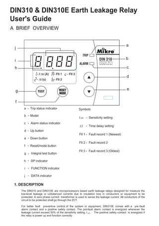
- 1. DIN310 & DIN310E Earth Leakage Relay User's Guide A BRIEF OVERVIEW a - Trip status indicator c Alarm status indicator d Up button e Down button f Reset/mode button g Integral test button h DP indicator i FUNCTION indicator a c d e f g h i j j DATA indicator 1. DESCRIPTION Symbols I - Sensitivity setting t - Time delay setting Flt 1 - Fault record 1 (Newest) n Flt 2 - Fault record 2 Flt 3 - Fault record 3 (Oldest) n The DIN310 and DIN310E are microprocessors based earth leakage relays designed for measure the low-level leakage or unbalanced currents due to insulation loss in conductors or equipment to be protected. A zero phase current transformer is used to sense the leakage current. All conductors of the circuit to be protected shall go through the ZCT. For better fault preventive control of the system or equipment, DIN310E comes with a pre-fault alarm contact and a positive safety contact. The pre-fault alarm contact is energized whenever the leakage current exceed 50% of the sensitivity setting, I . .The positive safety contact is energized if the relay is power up and function correctly. b b Model- - - - - - - - -
- 2. 2. LIGHT INDICATORS Indicator Trip Alarm FUNC DP DATA Status 0 0 0 0 0 No auxiliary supply 0 0 0 0 1 Normal condition, no tripping 0 B X X X Leakage current exceeded 50% of the sensitivity setting, I n. 0 FB X X X Leakage current exceeded 85% of the sensitivity setting, I n. Time delay countdown started 1 1 0 0 B Delay time lapsed and relay tripped 0 X 1 0 1 Scroll through setting 0 X 1 1 1 Scroll through records 0 X B 0 1 Programming mode The indicators display the status of the system as follow: 1 = ON 0 = OFF X = Don't care B = Normal blinking FB = Fast blinking FUNC = FUNCTION 3. PUSH BUTTON OPERATIONS Table 1: System status FUNC DP DATA off off Real time leakage current 1 off Sensitivity setting 2 off Delay time setting A on Fault record 1 (Newest) b on Fault record 2 c on Fault record 3 (Oldest) Table 2: Function codes Message Description ' Ct' Error in ZCT connection 'tSt' Relay tripped under test mode Table 3: Display messages a. Integral Trip Test: Press the “TEST” button to perform an integral test on the relay ranging from analog sensing circuitry to output contact(s) of the relay as well as the relay indicators and display. b. Trip Reset: Press the “RESET” button to reset the relay when tripped c. CT Fault: Press the “RESET” button to reset the relay after fixing the ZCT connection error. No reset function is carry out if the fault is not cleared. d. View Setting: When the relay is not under tripped condition or ZCT fault condition pressing the “RESET” button will scroll through the various functions.
- 3. 5. OUTPUT CONTACT a. Trip Contact This is the latching type contact. It is energized either relay tripped due to leakage fault or broken connection between the relay and the ZCT. b. Positive Safety Contact * Contact energized when the relay is power up and function correctly with no tripping. c. Pre -Fault Contact * Contact energized when the leakage current exceeded 50% of the sensitivity setting and de- energized when the leakage current drop below 45% of the sensitivity setting. Contact is energized and latched if the relay is either tripped due to leakage fault or broken connection between the relay and the ZCT. 6. RECORD 4. REMOTE INPUT * e. Program Setting: Step 1: Press “RESET” button until the function digit shows the required function. Step 2: Press the “UP” and “DOWN” button simultaneously and hold for 1 sec to enter programming mode. The function digit will blinks to indicates the relay is in programming mode. Step 3: Use the “UP” or “DOWN” button to select the desired value. Step 4: To save the selected value, press the “UP” and “DOWN” button simultaneously and hold for 1 sec again. It will exit the programing mode with data digits displaying new setting. To exit programming mode without saving the selected setting, press the “RESET” button once. The DIN310 / DIN310E incorporates a fault record function.It records the 3 latest tripped faults current and stored in non-volatile memory. No data is recorded if the tripping is triggered by integral test button. 7. TECHNICAL DATA The DIN310E built in one remote reset input. This digital input is to remotely reset the relay when tripped or after fixing the ZCT connection error. To reset the relay, make a connection between terminals 4 and 5 of the relay. AUXILIARY SUPPLY DIN310-230(6)......................................................184 ~ 276 VAC DIN310E-230(6)..................................................184 ~ 276 VAC Rated frequency..................................................50Hz or 60 Hz VA rating.............................................................3 VA typical SETTING RANGES Sensitivity adjustment.........................................30mA, 50mA, 0.10A – 1.00A (Step = 50mA), 1.00A – 10.0A (Step = 1.00A) Delay time adjustment.........................................Instantaneous, 0.1s – 3.0s (Step = 0.10s) RECORD Fault record.........................................................3 latest tripped fault currents Storage................................................................Non-volatile memory INPUT Remote reset.......................................................N.O. dry contact OUTPUTS Trip contact..........................................................5A / 250V AC1 Positive safety contact *......................................5A / 250V AC1 Pre-fault alarm contact *......................................5A / 250V AC1 *Applicable to DIN310E series only
- 4. 8. CONNECTION DIAGRAMS 9. CASE DIMENSION TRIP CONTACT LOAD L1 L2 L3 N 62 3 4 5 71 8 9 10 11 12 13 14 L N AUX SHUNT TRIP MIKRO ZCT DIN310 TRIP CONTACT SAFETY CONTACT LOAD L1 L2 L3 N 62 3 4 5 71 8 9 10 11 12 13 14 L N AUX CONTACTOR MIKRO ZCT DIN310E REMOTE RESET Typical application diagram for DIN310 Typical application diagram for DIN310E Front Side 71 mm 20mm 45mm 20mm 70 mm 85mm 30mm 20mm20mm CONTACT SPECIFICATION Contact arrangement:..........................................Change-over Contact material:..................................................Silver alloy Expected electrical life:........................................100,000 at rated current Expected mechanical life:....................................5x10 operations INDICATORS Pre-fault alarm:...................................................Red indicator Time delay:...........................................................Red indicator Leakage trip:........................................................7-segment display & red indicator ZCT fault:.............................................................7-segment display & red indicator Real-time leakage current:...................................7-segment display ZERO-PHASE CURRENT TRANSFORMER To operate with Mikro's ZCT series of current transformer MECHANICAL Mounting method:.................................................Standard 35mm DIN rail mounting Approximate weight:............................................ 0.38kg (excluding ZCT) 6 *Applicable to DIN310E series only ALARM CONTACT