SlideShare ist ein Scribd-Unternehmen logo
1 von 34
Downloaden Sie, um offline zu lesen
CHAPTER 3
  CONSTRUCTION AND TESTING OF SUBGRADE
WHAT IS SUBGRADE?


                                SUBGRADE

                             EMBANKMENT

                              FOUNDATION


               The top surface of an embankment or cut section,
                    shaped to conform to the typical section
               upon which the pavement structure and shoulders
                              will be constructed.


                                 Figure 3.1
   2012 v1.0                                                      3-1
IMPORTANCE OF SUBGRADE

             Heavy trucks and buses are continually loading our pavements. These loads are
      transmitted through the pavement to the subgrade. In effect, the loads applied to the
      surface of the pavement are transmitted through the structure, deforming or otherwise
      destroying the integrity of the subgrade. How the subgrade is going to react under the
      application of traffic loads is of great concern. As illustrated in Figure 3.2, how the load
      gets transferred to the subgrade and how the subgrade can handle that load has a strong
      influence on the overall quality of the pavement. If the pavement is thin as shown in
      the right hand sketch, the stress imposed by the traffic load through the pavement is
      distributed over a small area, making for high stresses on the subgrade. If the subgrade
      is poorly prepared (improper compaction, excessive moisture, etc.) or has a very low
      strength (such as with highly plastic clays), the subgrade cannot resist these high stresses
      and ruts will form which could lead to significant damage to the pavement. If the
      pavement is thick as shown in the left hand sketch, the stress imposed by the traffic load
      through the pavement is distributed over a large area, making for low stresses on the
      subgrade. Even if the subgrade is made up of low strength soils such as the highly plastic
      clays mentioned above, you can still have a good performing pavement because the stress
      projected through the pavement is lower than it would be with a thin pavement and if
      the design is done properly, these stresses should be lower than what can be resisted by
      the subgrade. It is still important to have the subgrade soils properly compacted when a
      thick pavement is used because rutting can still take place.

             As mentioned above, reducing stress can be accomplished by simply building a
      thicker pavement. This looks great on paper and is practical to a point. But pavement items
      are very expensive. Optimizing the pavement itself is very important, but there comes a
      point where this is not practical. Providing a strong subgrade is essential. Increasing the
      strength of subgrade allows us to use a thinner pavement.


      Figure 3.2 - Load Distribution Characteristics of Thick Versus Thin Pavement

3-2                                                                                 2012 v1.0
Figure 3.3

      A California Bearing Ratio (CBR) test is run on soils to gauge the strength of the
subgrade as compared to a dense graded aggregate. CBR is one of the major factors
used in pavement design to determine how thick the pavement should be. Since we
have chosen a pavement based on certain subgrade conditions, we must have the best
subgrade conditions under our pavement for it to perform its job.

       To understand the impact of CBR (subgrade strength) on the pavement, lets look
at some typical CBR values. A clayey soil generally has a low CBR value (less than 8).
Sands are more granular and drain better and will generally have CBR values between
15 and 35. Gravel will have the best CBR values, generally 25 and up. That is why it is
suggested to save the best material to cap the subgrade. The higher the CBR of foundation
soils you have, the less pavement structure is needed, the more economical the design.

      CBR values are also used as criteria for borrow material.


     2012 v1.0                                                                              3-3
TYPES OF SUBGRADE MATERIALS


                    Types of Subgrade Material

                        •   Material in place – soils in a cut section
                        •   Imported Material – borrow material and regular
                            excavation material
                        •   Treated Material
                            • Material in place or imported material
                            • May be considered in design of the pavement structure
                            • Improves engineering properties of the soil
                            • Provides platform to compact subsequent layers


            The Specifications list three types of material which are acceptable for use as
      subgrade. Each type has different characteristics and must be dealt with accordingly.

              Material in Place - Whenever the roadway will be in a cut section, subgrade will be
      in original ground. The density of most soils is at approximately 85 to 90 percent of our
      Standard Proctor density (VTM-1 or VTM-12) in it’s natural state. Soil in this condition
      falls short of having the strength to support our pavement structure. In order to achieve
      our desired strength, these soils must be compacted.

             The specifications require that material in place be scarified to a depth of 6 inches for
      a distance of 2 feet beyond the proposed edges of pavement on each side. This is illustrated
      in Figure 3.4 on Page 3-5. This requirement applies to both cut and fill sections.

             Imported Material - Subgrade material consisting of imported material is called
      “borrow material”. This material can come from regular excavation from another area
      in the project, from commercial sources, or from local pits or quarries obtained by the
      Department or the Contractor.

             Placement and compaction of borrow material would follow the same procedures
      and practices that are used when placing and compacting soil taken from a cut site on the
      project.

             Treated Material in Place - For some soils, simply scarifying and compacting will
      not produce the desired strength needed to support our pavement. In these cases it can
      be very cost effective to stabilize the subgrade with lime, cement, fly ash or a combination
      thereof. This provides a solid foundation for the remainder of the pavement. Stabilized
      subgrade provides two very important benefits:


                     Benefits of Soil Stabilization

                    - Becomes part of pavement structure
                    - Improves structural integrity of layers placed above it

3-4                                                                                  2012 v1.0
COMPACTION REQUIREMENTS FOR SUBGRADE

                       Density Requirements for Subgrade
                         100% Density for top 6 inches

                   Percent +4 Material      Minimum % Density
                          0 - 50 %               100 %
                         51 - 60 %                95 %
                         61 - 70 %                90 %


                       Moisture Requirements for Subgrade

                            Optimum moisture ± 20%


                          Why 100% Density at Subgrade

                      • Promotes uniformity of subgrade
                      • Greater density improves strength


               Where do we obtain 100% Density at Subgrade?


                                   Figure 3.4
   2012 v1.0                                                    3-5
Figure 3.5

             Whether subgrade consists of material in place, treated material in place or imported
      material, it must be compacted to 100% density (95% for soil-lime). Field densities are
      compared to VTM-1 or VTM-12. When subgrade material contains large quantities of
      material retained on the No. 4 sieve, use Table 3-1 to determine the minimum required
      density.


                           Percent                             Minimum
                         +4 Material                       Percent Density
                             0 - 50                              100
                            51 - 60                               95
                            61 - 70                               90

                                               Table 3-1


3-6                                                                                 2012 v1.0
SUBGRADE STABILIZATION

      The top of subgrade, as with other portions of an embankment, can be stabilized
by two primary methods: mechanical and chemical.


                   METHODS OF SUBGRADE STABILIZATION

                 Mechanical                              Chemical
                 Rolling                                 Cement
                 Geotextile                              Lime
                                                         Fly Ash
                                                         Lime-Fly Ash
                                                         Cement-Lime
                                                         Salts


Mechanical Stabilization


                            Mechanical Stabilization - Rolling

                              Often referred to as Compaction

                              -    Density Increases
                              -    Permeability Decreases
                              -    Compressibility Decreases


       In the case of mechanical stabilization, rolling is the simplest and most commonly
used method. Appendix E details the various types of rollers available and which
type roller works best for certain soils. For subgrade stabilization however, the most
commonly used rollers are pneumatic, static steel wheel, and vibratory steel wheel. The
results of rolling include increasing density, increasing strength, decreasing permeability
and decreasing compressibility.


                            Mechanical Stabilization - Rolling

                                  Match equipment to soil type

                      Fine-grained soils – clays and silts

                        •     Sheepsfoot Roller
                        •     Rubber Tire Roller
                        •     Smooth Wheel Roller

                      Coarse-grained soils – gravels and sands

                        •     Crawler Tractor
                        •     Vibratory Roller
     2012 v1.0          •     Rubber Tire Roller                                              3-7
Mechanical Stabilization – Geosynthetics

             A method of mechanical stabilization that is gaining popularity throughout the
      commonwealth is to use Geosynthetics. The types of Geosynthetics that are most likely
      used for stabilization are geotextiles, geogrids, and geocomposites.
             -   Geotextiles – Consist of synthetic fibers made into flexible, porous fabrics by
                 standard weaving machinery or are matted together in a random nonwoven
                 manner.
             -   Geogrids – Plastics formed into open, gridlike configuration
             -   Geocomposites – A combination of Geosynthetics such as a Geotextile attached
                 to a dimpled plastic sheet used for pavement drainage, or a Geotextile attached
                 to a geogrid.
             Geotextiles have been used in roadway construction in Virginia since the early
      1970’s, primarily in erosion and siltation control. In the 1980’s, the construction industry
      began using geosynthetics in earth stabilization applications. The primary benefit of
      using a geotextile is that you get separation between the poor quality subsoil and the
      better quality backfill material. An additional benefits of using a geotextile or a geogrid is
      an increased resistance to spreading by means of the reinforcement. Because of this, the
      Department can save a substantial amount of money by using geosynthetics to “bridge”
      soft subgrade areas and reduce or eliminate undercutting. The local District Materials
      Engineer can give guidance as to the types of materials that can be used and where they
      can be used.


                            Subgrade Stabilization using Geotextiles

                            -   Provides separation of soil/aggregate
                            -   Provides reinforcement of base
                            -   Placed at subgrade elevation
                            -   Rolled out and pulled tight – limit wrinkles
                            -   Seams connected by 2 foot overlap


              Geotextiles are the most widely used geosynthetic. In this chapter we will discuss
      how we use geotextiles at the subgrade and under embankments. The geotextile performs
      the primary functions of reinforcement and separation when used at the subgrade and on
      the embankment footprint. Typically the geotextile is placed in the desired area, pulled
      tight to limit wrinkles, and if at the subgrade, an over lap of 2 feet is provided at the seams.
      However, to reinforce an embankment, all seams are to be sewn to allow for the tensile
      stress to be transmitted. It is critical that the correct geotextile is used in the appropriate
      place, since the properties of various styles will affect the overall performance of the
      structure.

             Geogrids are also becoming more widely used in Virginia. While these can be
      used to reinforce a subgrade, or an undercut, they are most likely to be used to reinforce
      a slope or embankment foundation. Careful attention must be paid to the specifications
      or contract documents for geogrid selection and installation.


3-8                                                                                    2012 v1.0
Chemical Stabilization


                      Chemical Stabilization

                         •   Cement
                         •   Lime
                         •   Flyash
                         •   Lime & Cement
                         •   Salts (Sodium Chloride, Calcium Chloride,
                             Potassium Chloride)


        In the case of chemical stabilization, the procedure is to add a chemical that reacts
with the soil, changes its physical and/or chemical characteristics and forms a more stable
material. The most commonly used methods of chemical stabilization of subgrade soils
are listed above. These materials are mixed with the subgrade soils and are allowed a
curing period to react with the soil and harden.

       Some of these materials (such as lime, lime-fly ash, and salts) can be mixed with
water to form a slurry and are then pressure injected into a soil mass to form a stable
structure foundation or to stabilize a landslide.


       Hydraulic Cement Stabilization

       Commonly called “soil cement”, hydraulic cement stabilization is the most widely
used method of stabilizing soils. The method is acceptable for a wide variety of soils (See
Table 3-2).


                      Chemical Stabilization – Soil-Cement

                         •   Used in sandy and gravelly soils (10 to 35% fines)
                         •   Used in some fine-grained soils with low plasticity
                         •   Not used in very coarse sands and gravels
                         •   Not used in highly plastic clays
                         •   Not used in organic soils


       Cement is usually added to existing material in place. This is normally done with
a self-propelled, self-powered, rotary mixing or tilling machine. The subgrade layer is
scarified to the specified depth, cement and water added, and mixed by the same machine
in one pass. Other machines which require a separate pass for each operation may be
used but are not common.

       The amount of cement to add to the soil to achieve the desired results depends
on the soil type and is determined in the design phase by performing laboratory testing.
Typical cement contents are shown in Table 3-2. This amount of cement can be specified
either by weight or by volume. PCA recommends specifying the cement content by
weight, however VDOT typically specifies the cement by volume since there are fewer
field calculations needed to determine application rate.


     2012 v1.0                                                                                  3-9
CEMENT REQUIREMENTS
                                           (by Soil Type)

                                               Usual Range in Cement
                                                     Requirement
                                             Percent by        Percent by
                           Soil Type          Volume             Weight
                           Clean Gravel        5–7                3–5
                           Clean Sand          7–9                5–8
                           Dirty Gravel/Sand   7 – 10             5–9
                           Silt                8 – 12             7 – 12
                           Clay               10 – 14            10 – 16


                                               Table 3-2

             When using cement stabilization, the control necessary to ensure that a quality
       product is produced consists of the following:


                                FIELD CONTROL OF SOIL CEMENT

                                  1.   Application rate
                                  2.   Moisture
                                  3.   Depth control
                                  4.   Compaction
                                  5.   Curing


             Application Rate

              Cement stabilized subgrade is specified as a percentage of cement per unit volume
       or by unit weight and a depth of manipulation (i.e. 10% cement by volume, 6” depth
       - 10% cement by weight, 6” depth). Cement can be applied by either using bag cement
       or bulk loads with the latter being the most common. The application rate depends on
       the percentage by volume or weight, depth and width of spread. Application rate can be
       controlled by either a rate per foot basis or a rate per square foot basis. The following
       nomographs (Pages 3-11 & 3-12) are used to determine the application rate when the
       cement content is specified as a percentage of weight.

              The application rate is determined prior to placement of the cement to ensure
       that an adequate amount of cement will be spread to achieve the desired percentage of
       cement. Both the contractor and inspector should be aware of how much cement is to be
       applied to achieve the desired outcome.


3-10                                                                              2012 v1.0
PCA Construction Manual – Cement by Weight

2012 v1.0                                                3-11
PCA Construction Manual

3-12                             2012 v1.0
EXAMPLE #1
Given: The plans call for 10% cement by weight, 6” depth. There are two 12 foot lanes.
The base aggregate is to extend 1 ft. beyond the edge of pavement on each side. The width
to be treated is 1 ft. beyond the edge of the base stone on each side. The Dry Density of the
soil to be treated is 112 lb/ft3.

The contractor plans to spread the cement for the entire width in four sections or pulls.
The load of cement in question contains 22.5 tons.

Question: How many feet of roadway should this load of cement treat?

Solution:       24 ft. (Two 12 ft. lanes)
            +    2 ft. (base aggr.)
                 2 ft. (beyond base)
                28 ft. width of treatment

                28 ft. width of treatment ÷ 4 sections (1/4 width) = 7 ft. pulls

Use the nomograph on Page 3-14 with 112 lb/ft3 and 10% cement. This yields 10.2 lbs.
of cement per cubic foot of compacted soil-cement. Then go to nomograph on page 3-15
with 10.2 lbs. of cement per cubic foot of compacted soil-cement, to 6” depth, and 7’ pull
width. This yields 36 lbs. of cement per foot per pull.

                22.5 tons X 2000 lbs/ton = 45,000 lbs. on this load.

Since the contractor will make four pulls this figure needs to be quartered to 11,250 lbs.
per pull.

                11,250 lbs./pull ÷ 36 lb/ft = 312.5 ft. per pull.

Answer: For the contractor to apply cement at the specified application rate of 10% by
weight for 6” depth of treatment; Making four pulls from a 22.5 ton load of cement should
cover 312.5 ft. by 28 ft. in width.


     2012 v1.0                                                                                  3-13
3-14   2012 v1.0
2012 v1.0   3-15
EXAMPLE #2
       Given: The plans call for 12% cement by volume, 8” depth. Width of treatment is 28 feet.
       The net weight of the cement in the tanker is 22.5 tons.

       Question: How many feet of roadway should this load of cement treat?

       Solution: Application Rate = [(WT)(DT)] [(DC)(94)]

                  Where = WT    =   Width of Treatment in feet
                          DT    =   Depth of Treatment in feet
                          DC    =   Design Cement Content (Volume in Decimal Form)
                          94    =   Unit Weight of Cement in lbs/ft3
                  Example = WT = 28 feet
                             DT = 0.666 feet (8 inches)
                             DC = 0.12 (12% by Volume)

                  Application Rate = [(WT)(DT)] [(DC)(94)]

                                    = [(28 ft.) (0.666 ft.)] [(0.12) (94 lbs/ft3)]

                                    = [18.648 ft2] [11.28 lbs/ft3]

                                    = 210.35 lbs/ft

                  Application Length = Net Weight of Cement
                                        Application Rate

                                      = 22.5 tons x 2000 lbs/ton
                                               210.35 lbs/ft

                                      = 45000 lbs.
                                        210.35 lbs/ft

                                      = 214 feet

       Answer: A load of 22.5 tons of cement applied at the rate of 12% by volume for 8” depth
       of treatment should cover 214 ft. by 28 ft. in width.


3-16                                                                                 2012 v1.0
Moisture

      Proper moisture control is crucial with cement treated subgrade. Because of the fine-
grained cement, the soil has a tendency to “dry out”. Best results can be obtained when
the mixture is brought to optimum or within 20% above optimum of the original soil. The
specifications require the mixture have moisture of not less than optimum or more than
optimum by 20% above optimum. This is graphically illustrated in Fig. 3.6.

       Constant moisture checks are needed. Check the soil moisture prior to applying
the cement. The Contractor will use this “beginning” moisture to figure how much water
to add to get the material to optimum moisture. In most cases water is added during
mixing to bring the soil to the optimum moisture content. Check the moisture after the first
pass of the mixer. This way the Contractor can add water if necessary before compaction.
Moisture checks should also be run periodically while compacting the mixture to ensure
that optimum moisture is maintained throughout the rolling operation. During finishing,
maintain moisture by lightly sprinkling the surface with water.

                               CHECK MOISTURE …
                    1. Before applying cement
                    2. After mixing / before rolling
                    3. With compaction testing


                          MOISTURE CONTROL


                                                               (0 to 20% of optimum)

                                                               (10 to 20% of optimum)
                                        Figure 3.6

     2012 v1.0                                                                                3-17
Depth Control

               Having the proper depth of treatment is one of the most important factors affecting
       the final product. Deviation from the specified depth either by an increase or decrease
       has an effect on the strength of the treated material. (see Fig. 3.7 below) As stated earlier,
       stabilized subgrade is part of the pavement structure. If the treated depth is less than that
       specified, we are compromising the pavement’s depth. If the treated depth is greater than
       that specified, the cement will be dispersed throughout a greater volume and the entire
       course will be weak.

             The general rule of thumb for soil compaction applies here: 8” of loose soil (after
       mixing) will compact to 6”. This should be checked.

               After the material has been compacted and tested for density it must be checked
       for depth. When material in place is tested the aid of a liquid solution of phenolphthalein
       in distilled water is needed. This can be obtained from your District Materials Personnel.
       When the solution comes in contact with cement or lime it turns purple in color. Check
       the depth of cement by using a pick to dig a hole and, using a medicine dropper, apply
       the solution to the side of the hole. The purple indicator disappears at the bottom of the
       cement. A stake placed flat on the ground across the hole and a ruler are used to measure
       the depth.


                           EFFECTS OF INCORRECT DEPTH
                     If plans called for 6” depth and 10% by volume
                     assuming application rate is correct …

                             too                  JUST                    too
                            deep                  RIGHT                 shallow


       YIELDS: 8.5%                              10%                          12%


                                                Figure 3.7


3-18                                                                                  2012 v1.0
Compaction


                      8” Loose = 6” Compacted


           8”                                                         6”


                               COMPACTION CRITERIA

              -  Minimum 100% of maximum theoretical density
              -  Sufficient number of rollers to achieve density within
                4 hours after mixing
              - Any portion on which the density is below the specified
                density by more than 5 lbs/ft3 shall be removed and replaced
              - Minimum rate of compaction tests – 1 per ½ mile per width


       The Specifications require that soil cement be compacted to 100% of the maximum
density. Compaction equipment is subject to the approval of the Engineer. A sufficient
number of compaction units should be provided to ensure that the specified level of
density and the completion of the compaction of the soil cement section is accomplished
within 4 hours from the time water is added to the mixture. The minimum rate of
compaction testing is one test per ½ mile for each application width or pass. Any portion
on which the density is below the specified density more than 5 lb/ft3 shall be removed
and replaced.


       Curing

        Just as with hydraulic cement concrete, cement stabilized subgrade must be cured
to develop the desired strength. Once the grade has been approved the next course may
be placed. In order that the grade does not dry out, the specifications require it to be kept
moist. This will aid the curing. The contractor may elect to use an asphalt cover material
in lieu of moist curing. However, if the next course is not placed within 7 days, it must be
protected with an asphalt cover material.


     2012 v1.0                                                                                 3-19
When material may be exposed to freezing temperatures during the first 24 hours
       of curing, the contractor shall protect the stabilized material from freezing for 7 days or
       cover the soil-cement surface with the next pavement course within 4 hours after the
       cement stabilization has been finished as specified.


                                               Figure 3.8


       OTHER SUBGRADE STABILIZATION METHODS


              Lime Stabilization


                                              SOIL LIME

                            Used in fine-grained soils – clays and silts
                            Used in wet soils
                            Not appropriate for non-plastic soils – sands and
                            gravels


                                              SOIL LIME

                            Reduces plasticity of soils – lowers PI
                            Provides cementation
                            Helps to “dry” soils
                            Improves strength of soils (CBR)
3-20                                                                                2012 v1.0
Lime stabilization works very well with fine-grained soils, particularly heavy
clays because it changes the plasticity characteristics of the clay. The addition of lime to a
wide variety of soils greatly improves its load carrying capacity. It should be noted that
although lime can be used with granular soils, you can generally get greater strength gain
by using cement for the same money spent to use lime.


                             SOIL LIME - CONSTRUCTION

                            1.   Application rate
                            2.   Scarify and pulverize soil to required depth
                            3.   Spread lime
                            4.   Spray water and mix
                            5.   Cure
                            6.   Final mixing
                            7.   Compaction


       The application rate of the lime will be shown on the plans or can be as directed
by the Engineer (generally the District Materials Engineer). The lime may be applied to
the partially pulverized material as a slurry or in dry form. Hydrated lime or quicklime
can be used. When quicklime is used in a dry form, it is to be applied at the same rate as
hydrated lime.

        Lime stabilization should be done in stages. In the first stage, the prepared roadbed
is scarified to the depth and width required for the stabilized layer. After scarifying, the
material is to be partially scarified. The depth of scarification, pulverization and blading
should be controlled in such a manner that the surface of the roadbed below the scarified
material shall remain undisturbed and conform to the established cross section. Prior to
the beginning of stabilization work, material retained on the 3” sieve is to be removed
from the roadbed.

       If quicklime is slaked to produce a slurry, correction factors need to be applied to
make sure the proper amount of lime is being used (see Section 306.03 of the specifications
for correction factors).

       Lime applied by slurry generally causes less dust problems than using dry lime.

       Regardless of the system, the spreading equipment should uniformly distribute
the lime without excessive loss. No equipment, except water trucks and equipment used
for mixing and spreading, is to travel on the spread lime until mixed.

      This process generates a lot of heat and there will be a loss of moisture in the soil.
Sufficient water should be added to make sure that the moisture content of the mix at
time of compaction is not less than the optimum moisture content of the mix nor more
than optimum plus 20 percent of optimum.


     2012 v1.0                                                                                   3-21
Lime and water are mixed throughout the scarified material as thoroughly
    as practical by using a disc harrow, scarifier tines and blading, or by other approved
    methods. Spread the mix over the roadway and seal roll with a steel wheel or pneumatic
    tire roller to retard loss of moisture and allow to cure. Curing is considered completed
    when a uniform material is produced in which at least 60 percent of the material (except
    aggregate particles) passes the No. 4 sieve or 24 hours have lapsed since the beginning of
    mixing, whichever occurs first.


                                         Soil Lime – Cure

                                Cure up to 24 hours or until at least
                                       60% passes #4 sieve


          Final mixing will take place. If a stationary plant is used to mix the soil and lime,
    the material can be placed, compacted and finished immediately after mixing.


                                     Soil Lime – Compaction

                            •    Same compaction equipment
                            •    95% density
                            •    Moisture just prior to compaction, optimum
                                 to + 20% optimum


          Unlike soil-cement mixtures, soil-lime mixtures are compacted to a density of 95
    percent of the maximum theoretical density of the mixture determined in accordance with
    VTM-1 or VTM-12. Final rolling is done with a pneumatic tire roller. Final compaction
    and finishing must be completed within 12 hours after final mixing.

           After finishing of the treated subgrade, no vehicles (except the water truck) will be
    permitted on the compacted soil-lime mix for a period of 7 days or until the next layer of
    the pavement structure is placed, whichever is less, to allow for final curing. During the
    final curing period, the soil-lime mix is lightly sprinkled with water at frequent intervals
    to prevent drying of the mix. If at the end of 7 days the contractor has not placed the
    pavement course, the contractor must place liquid asphalt and a cover of fine aggregate
    on the mix.

           Salts

           Stabilization of soils have been accomplished with salts such as sodium chloride,
     calcium chloride, or potassium chloride. This method of subgrade treatment has been
     successful, but the treated material must be covered quickly or the salt will redissolve.
     Chloride is very expensive and thus is not a very cost effective method of treatment.
     Rusting of equipment by this method is also a problem.
3-22                                                                           2012 v1.0
Lime/Fly Ash

       Fly ash by itself provides no strength gain for soil. However, if lime is added with
the fly ash, they will react to provide cementation of the soil.

       Lime Cement

       In some eastern areas of the state, lime and cement are used together to stabilize
soil. The lime is used to dry the silty sands that are virtually saturated, and then cement
is added to improve its strength. It is quite expensive, but sometimes may be proven to
be cost effective because you aren’t undercutting a good quality material that can give
you good strength if dried and treated with cement.


TREATMENT OF UNSUITABLE SUBGRADE MATERIAL

       When solid rock is encountered at subgrade, the roadbed must be excavated below
the elevation shown on the plans and backfilled in accordance with Road and Bridge
Standard RU-1 (606.01). This standard is reprinted at the end of this chapter.

      Other unsuitable materials include saturated material, high plasticity clays, or other
low CBR material. These must also be undercut and backfilled with approved material.


PROTECTING THE WORK

       After subgrade is finished and has been checked and approved, it must be
maintained. Any deficiencies in compaction, grade or moisture must be corrected before
subsequent layers can be placed. If subgrade becomes eroded or distorted prior to
placing subsequent layers, it must be scarified, reshaped and recompacted to the original
requirements. If subgrade becomes unstable after placing any or all of the pavement, the
unstable area must be undercut and reconstructed properly.

      The above is a specification requirement. Having to go back and re-work areas
which have been completed is time consuming and costly. The same procedures for
grading to drain with embankments also apply to protecting the work at any stage of
construction.


TESTING AND INSPECTION OF SUBGRADE

       After scarifying and compacting, subgrade must be tested for compaction and
checked to ensure a typical cross section and uniform grade before subsequent courses
can be placed. The minimum rate of density testing for untreated subgrade material in
place is one test per 2000 linear feet of roadway (full width). Before pavement items are
placed on subgrade, it must be visually checked for soft spots, depressions, etc. Passing
compaction tests don’t necessarily mean subgrade is ready for the pavement. Any
deficiencies must be corrected prior to placing subsequent layers.


     2012 v1.0                                                                                 3-23
OBSTRUCTIONS AT SUBGRADE

              The materials exposed at subgrade elevation, or in areas that are to receive fill must
       be visually evaluated to determine if construction operations may proceed. If the materials
       exposed consist of rock, existing hydraulic cement concrete pavement, existing asphalt
       concrete pavement or unsuitable materials, these must be handled appropriately.

              If solid rock is encountered at subgrade elevation, it must be removed to the depth
       specified in Standard Drawing, RU-1, Standard Method for Undercutting Rock. The
       reason that the rock must be removed is to provide for a uniform base upon which to
       place the pavement. If the pavement is placed on a base that provides irregular support,
       then the pavement may deform in the areas where there is limited support.

              If existing pavements are encountered, depending on where they are relative to
       the future subgrade elevation, they are handled differently. It also depends on the type
       of pavement as to how the materials will be handled. The figures on Pages 3-25 and 3-26
       describe what to do. It is important to remember that adequate drainage be maintained
       and that any excess materials are properly handled.

              If highly plastic clays, organic materials or very wet materials are encountered at
       subgrade elevations, these materials must be either removed and replaced or dried out
       so they can be re-used. The disposition of these types of materials is usually described in
       the plans.


3-24                                                                                 2012 v1.0
2012 v1.0   3-25
3-26   2012 v1.0
2012 v1.0   3-27
CHAPTER 3
                                       Study Questions
       1.                    is the top surface of the embankment and the foundation
            for the pavement structure.


       2. Subgrade must be scarified for a distance of                       beyond the
          proposed edges of pavement to a depth of                    and recompacted
          to the original requirements.


       3.                      days after placement of the Cement Stabilized Subgrade
            the next course of pavement or approved cover material must be applied.


       4. True of False. Cement is used with soil or aggregate to make the soil or
          aggregate more workable.


       5. Why is lime used with soil?


       6. The tolerance on the optimum moisture content at which aggregate must be
          compacted is                 .


       7. The tolerance on the          optimum     moisture    content   for   cement
          treated subgrade, is                            .


       8. The most common type of geosynthetic used is a                              .

       9. True or False. Sewing of embankment stabilization fabric seams is not
          required.


       10. What is the minimum number of tests required for finished subgrade from
           Station 453+60 to Station 553+60?


       11. Cement Stabilized Subgrade has been placed 48 feet in width from Station
           392+20 to Station 550+60 with a paver application width of 12 feet. Determine
           the number of tests required and the density and moisture requirements.


3-28                                                                             2012 v1.0
CHAPTER 3
            Study Problems


2012 v1.0                    3-29
3-30   2012 v1.0
Practice Problem 1

                             Cement Application Rate
The plans call for 9.5% cement by weight, 6” depth. There are two 12’ lanes. The base
aggregate is to extend 1’ beyond the edge of pavement on each side. The width to be
treated is 1’ beyond the edge of the base stone on each side. The Dry Density of the soil
to be treated is 103.5 lb/ft3.

The contractor plans to spread the cement for the entire width in four sections or pulls.
The load of cement in question contains 20.28 tons.

How many feet of roadway should this load of cement treat?

Show your work!


     2012 v1.0                                                                              3-31
Practice Problem 2

                                    Cement Application Rate

       The plans call for 6.5% cement by weight, 7” depth. There are two 10’ lanes. The base
       aggregate is to extend 1 foot beyond the edge of pavement on each side. The width to be
       treated is 1 foot beyond the edge of the base stone on each side. The Dry Density of the
       soil to be treated is 115.5 lb/ft3.

       The contractor plans to spread the cement for the entire width in three sections or pulls.
       The load of cement in question contains 22.2 tons.

       How many feet of roadway should this load of cement treat?

       Show your work!


3-32                                                                             2012 v1.0
Practice Problem 3

                             Cement Application Rate

The plans call for 12% cement by volume, 6” depth. Width of treatment is 26 feet. The net
weight of the cement in the tanker is 23.09 tons.

How many feet of roadway should this load of cement treat?

Show your work!


     2012 v1.0                                                                              3-33
Practice Problem 4

                                   Cement Application Rate

       The plans call for 6.5% cement by volume, 6” depth. Width of treatment is 24 feet. The
       net weight of the cement in the tanker is 22 tons.

       How many feet of roadway should this load of cement treat?

       Show your work!


3-34                                                                            2012 v1.0

Weitere ähnliche Inhalte

Was ist angesagt?

2.bituminous mix
2.bituminous   mix 2.bituminous   mix
2.bituminous mix Vikas Rao
 
Transportation engineering various experiments
Transportation engineering various experimentsTransportation engineering various experiments
Transportation engineering various experimentsgayathrysatheesan1
 
Chapter3 road pavement
Chapter3 road pavementChapter3 road pavement
Chapter3 road pavementpokjak80
 
He unit iii 3d0f5751f8e65e10a1c08bba8255d4bc
He unit  iii 3d0f5751f8e65e10a1c08bba8255d4bcHe unit  iii 3d0f5751f8e65e10a1c08bba8255d4bc
He unit iii 3d0f5751f8e65e10a1c08bba8255d4bcsaibabu48
 
HIGHWAY CONSTRUCTION MATERIAL & PRACTICE
HIGHWAY  CONSTRUCTION  MATERIAL  &  PRACTICEHIGHWAY  CONSTRUCTION  MATERIAL  &  PRACTICE
HIGHWAY CONSTRUCTION MATERIAL & PRACTICEFresher Thinking
 
PAVEMENT DESIGN (Group 9)
PAVEMENT DESIGN (Group 9)PAVEMENT DESIGN (Group 9)
PAVEMENT DESIGN (Group 9)eddie fonte
 
Subgrade Stabilization: Materials & Methods
Subgrade Stabilization: Materials & MethodsSubgrade Stabilization: Materials & Methods
Subgrade Stabilization: Materials & MethodsJill Reeves
 
Construction of High Speed Highway and Test track
Construction of High Speed Highway and Test trackConstruction of High Speed Highway and Test track
Construction of High Speed Highway and Test trackNikhil Kumar
 
TRANSPORTATION , HIGHWAYS MATERIALS AND ITS TEST
TRANSPORTATION , HIGHWAYS MATERIALS AND ITS TESTTRANSPORTATION , HIGHWAYS MATERIALS AND ITS TEST
TRANSPORTATION , HIGHWAYS MATERIALS AND ITS TESTMahreen Zamir Abro
 
2.3 HIGHWAY TRANSPORTATION : HIGHWAY MATERIALS (TRE) 3150611 GTU
2.3 HIGHWAY TRANSPORTATION : HIGHWAY MATERIALS (TRE) 3150611 GTU2.3 HIGHWAY TRANSPORTATION : HIGHWAY MATERIALS (TRE) 3150611 GTU
2.3 HIGHWAY TRANSPORTATION : HIGHWAY MATERIALS (TRE) 3150611 GTUVATSAL PATEL
 
FLEXIBLE And Rigid Pavement
FLEXIBLE And Rigid PavementFLEXIBLE And Rigid Pavement
FLEXIBLE And Rigid PavementKhaliqur Rahman
 
Group index method
Group index methodGroup index method
Group index methodUsama Aslam
 
Project presentation on flexible pavement by Harshit Prakash Garg
Project presentation on flexible pavement by Harshit Prakash GargProject presentation on flexible pavement by Harshit Prakash Garg
Project presentation on flexible pavement by Harshit Prakash Gargharshit315
 
Mix design practice (bituminous mix) ce 463
Mix design practice (bituminous mix) ce 463Mix design practice (bituminous mix) ce 463
Mix design practice (bituminous mix) ce 463abhay mishra
 
PAVEMENT DESIGN & TYPES
PAVEMENT DESIGN & TYPES PAVEMENT DESIGN & TYPES
PAVEMENT DESIGN & TYPES Mahendra meena
 
Presentation on Laboratory Tests-Road Construction
Presentation on Laboratory Tests-Road ConstructionPresentation on Laboratory Tests-Road Construction
Presentation on Laboratory Tests-Road ConstructionTEJASWI SHARMA
 
Rigid Pavement Design Part II
Rigid Pavement Design Part IIRigid Pavement Design Part II
Rigid Pavement Design Part IISachin Kulkarni
 

Was ist angesagt? (20)

2.bituminous mix
2.bituminous   mix 2.bituminous   mix
2.bituminous mix
 
Transportation engineering various experiments
Transportation engineering various experimentsTransportation engineering various experiments
Transportation engineering various experiments
 
Chapter3 road pavement
Chapter3 road pavementChapter3 road pavement
Chapter3 road pavement
 
He unit iii 3d0f5751f8e65e10a1c08bba8255d4bc
He unit  iii 3d0f5751f8e65e10a1c08bba8255d4bcHe unit  iii 3d0f5751f8e65e10a1c08bba8255d4bc
He unit iii 3d0f5751f8e65e10a1c08bba8255d4bc
 
HIGHWAY CONSTRUCTION MATERIAL & PRACTICE
HIGHWAY  CONSTRUCTION  MATERIAL  &  PRACTICEHIGHWAY  CONSTRUCTION  MATERIAL  &  PRACTICE
HIGHWAY CONSTRUCTION MATERIAL & PRACTICE
 
PAVEMENT DESIGN (Group 9)
PAVEMENT DESIGN (Group 9)PAVEMENT DESIGN (Group 9)
PAVEMENT DESIGN (Group 9)
 
Subgrade Stabilization: Materials & Methods
Subgrade Stabilization: Materials & MethodsSubgrade Stabilization: Materials & Methods
Subgrade Stabilization: Materials & Methods
 
Subgrade
SubgradeSubgrade
Subgrade
 
Construction of High Speed Highway and Test track
Construction of High Speed Highway and Test trackConstruction of High Speed Highway and Test track
Construction of High Speed Highway and Test track
 
TRANSPORTATION , HIGHWAYS MATERIALS AND ITS TEST
TRANSPORTATION , HIGHWAYS MATERIALS AND ITS TESTTRANSPORTATION , HIGHWAYS MATERIALS AND ITS TEST
TRANSPORTATION , HIGHWAYS MATERIALS AND ITS TEST
 
2.3 HIGHWAY TRANSPORTATION : HIGHWAY MATERIALS (TRE) 3150611 GTU
2.3 HIGHWAY TRANSPORTATION : HIGHWAY MATERIALS (TRE) 3150611 GTU2.3 HIGHWAY TRANSPORTATION : HIGHWAY MATERIALS (TRE) 3150611 GTU
2.3 HIGHWAY TRANSPORTATION : HIGHWAY MATERIALS (TRE) 3150611 GTU
 
FLEXIBLE And Rigid Pavement
FLEXIBLE And Rigid PavementFLEXIBLE And Rigid Pavement
FLEXIBLE And Rigid Pavement
 
PAVEMENT DESIGN
PAVEMENT DESIGNPAVEMENT DESIGN
PAVEMENT DESIGN
 
Group index method
Group index methodGroup index method
Group index method
 
Project presentation on flexible pavement by Harshit Prakash Garg
Project presentation on flexible pavement by Harshit Prakash GargProject presentation on flexible pavement by Harshit Prakash Garg
Project presentation on flexible pavement by Harshit Prakash Garg
 
Mix design practice (bituminous mix) ce 463
Mix design practice (bituminous mix) ce 463Mix design practice (bituminous mix) ce 463
Mix design practice (bituminous mix) ce 463
 
PAVEMENT DESIGN & TYPES
PAVEMENT DESIGN & TYPES PAVEMENT DESIGN & TYPES
PAVEMENT DESIGN & TYPES
 
Presentation on Laboratory Tests-Road Construction
Presentation on Laboratory Tests-Road ConstructionPresentation on Laboratory Tests-Road Construction
Presentation on Laboratory Tests-Road Construction
 
Concrete pavement design
Concrete pavement designConcrete pavement design
Concrete pavement design
 
Rigid Pavement Design Part II
Rigid Pavement Design Part IIRigid Pavement Design Part II
Rigid Pavement Design Part II
 

Ähnlich wie CBR Test

Minor Project on design and analysis of flexible pavement with cement treated...
Minor Project on design and analysis of flexible pavement with cement treated...Minor Project on design and analysis of flexible pavement with cement treated...
Minor Project on design and analysis of flexible pavement with cement treated...PrashannaKumar2
 
highway materials and desihn.pptx
highway materials and desihn.pptxhighway materials and desihn.pptx
highway materials and desihn.pptxSekharJ4
 
highwaymaterial-150329085516-conversion-gate01 (1).pdf
highwaymaterial-150329085516-conversion-gate01 (1).pdfhighwaymaterial-150329085516-conversion-gate01 (1).pdf
highwaymaterial-150329085516-conversion-gate01 (1).pdfshainacivil
 
Chapter 1
Chapter 1Chapter 1
Chapter 1Lai Yen
 
IRJET- Flexible Pavement Design using Geo-Synthetic Material
IRJET- Flexible Pavement Design using Geo-Synthetic MaterialIRJET- Flexible Pavement Design using Geo-Synthetic Material
IRJET- Flexible Pavement Design using Geo-Synthetic MaterialIRJET Journal
 
Seminar report-3rd sem.pdf
Seminar report-3rd sem.pdfSeminar report-3rd sem.pdf
Seminar report-3rd sem.pdframbhuvansonkar1
 
Study on comparative flexible pavement thickness analysis using various desig...
Study on comparative flexible pavement thickness analysis using various desig...Study on comparative flexible pavement thickness analysis using various desig...
Study on comparative flexible pavement thickness analysis using various desig...eSAT Publishing House
 
IRJET- A Study on Reclaimed Asphalt Pavement (RAP)Material using Sub-Grade La...
IRJET- A Study on Reclaimed Asphalt Pavement (RAP)Material using Sub-Grade La...IRJET- A Study on Reclaimed Asphalt Pavement (RAP)Material using Sub-Grade La...
IRJET- A Study on Reclaimed Asphalt Pavement (RAP)Material using Sub-Grade La...IRJET Journal
 
Characterization of Pavement Materials
Characterization of Pavement MaterialsCharacterization of Pavement Materials
Characterization of Pavement MaterialsArnabKarmakar18
 
CHAPTER - 4 HIGHWAY II R = 4.pptx
CHAPTER - 4 HIGHWAY II R = 4.pptxCHAPTER - 4 HIGHWAY II R = 4.pptx
CHAPTER - 4 HIGHWAY II R = 4.pptxRoMa665066
 
Lecture one_introffffffffffffduction.pdf
Lecture one_introffffffffffffduction.pdfLecture one_introffffffffffffduction.pdf
Lecture one_introffffffffffffduction.pdfOmarAbdi39
 
Pavement Analysis and Design.pptx
Pavement Analysis and Design.pptxPavement Analysis and Design.pptx
Pavement Analysis and Design.pptxEmaan Sharma
 
Highway Construction Materials and Practice
Highway Construction Materials and PracticeHighway Construction Materials and Practice
Highway Construction Materials and PracticeSenthamizhan M
 
Pavement design
Pavement designPavement design
Pavement designhusna004
 

Ähnlich wie CBR Test (20)

Minor Project on design and analysis of flexible pavement with cement treated...
Minor Project on design and analysis of flexible pavement with cement treated...Minor Project on design and analysis of flexible pavement with cement treated...
Minor Project on design and analysis of flexible pavement with cement treated...
 
highway materials and desihn.pptx
highway materials and desihn.pptxhighway materials and desihn.pptx
highway materials and desihn.pptx
 
highwaymaterial-150329085516-conversion-gate01 (1).pdf
highwaymaterial-150329085516-conversion-gate01 (1).pdfhighwaymaterial-150329085516-conversion-gate01 (1).pdf
highwaymaterial-150329085516-conversion-gate01 (1).pdf
 
Highway Materials Unit-III
Highway Materials  Unit-IIIHighway Materials  Unit-III
Highway Materials Unit-III
 
Chapter 1
Chapter 1Chapter 1
Chapter 1
 
highway con..pptx
highway con..pptxhighway con..pptx
highway con..pptx
 
IRJET- Flexible Pavement Design using Geo-Synthetic Material
IRJET- Flexible Pavement Design using Geo-Synthetic MaterialIRJET- Flexible Pavement Design using Geo-Synthetic Material
IRJET- Flexible Pavement Design using Geo-Synthetic Material
 
Seminar report-3rd sem.pdf
Seminar report-3rd sem.pdfSeminar report-3rd sem.pdf
Seminar report-3rd sem.pdf
 
Study on comparative flexible pavement thickness analysis using various desig...
Study on comparative flexible pavement thickness analysis using various desig...Study on comparative flexible pavement thickness analysis using various desig...
Study on comparative flexible pavement thickness analysis using various desig...
 
IRJET- A Study on Reclaimed Asphalt Pavement (RAP)Material using Sub-Grade La...
IRJET- A Study on Reclaimed Asphalt Pavement (RAP)Material using Sub-Grade La...IRJET- A Study on Reclaimed Asphalt Pavement (RAP)Material using Sub-Grade La...
IRJET- A Study on Reclaimed Asphalt Pavement (RAP)Material using Sub-Grade La...
 
Road Aggregates
Road AggregatesRoad Aggregates
Road Aggregates
 
Different layers of flexible pavement
Different layers of flexible pavementDifferent layers of flexible pavement
Different layers of flexible pavement
 
Characterization of Pavement Materials
Characterization of Pavement MaterialsCharacterization of Pavement Materials
Characterization of Pavement Materials
 
CHAPTER - 4 HIGHWAY II R = 4.pptx
CHAPTER - 4 HIGHWAY II R = 4.pptxCHAPTER - 4 HIGHWAY II R = 4.pptx
CHAPTER - 4 HIGHWAY II R = 4.pptx
 
Pavements and paths
Pavements and pathsPavements and paths
Pavements and paths
 
Lecture one_introffffffffffffduction.pdf
Lecture one_introffffffffffffduction.pdfLecture one_introffffffffffffduction.pdf
Lecture one_introffffffffffffduction.pdf
 
Pavement Analysis and Design.pptx
Pavement Analysis and Design.pptxPavement Analysis and Design.pptx
Pavement Analysis and Design.pptx
 
Highway Construction Materials and Practice
Highway Construction Materials and PracticeHighway Construction Materials and Practice
Highway Construction Materials and Practice
 
Pavement design
Pavement designPavement design
Pavement design
 
Unit 4
Unit 4Unit 4
Unit 4
 

CBR Test

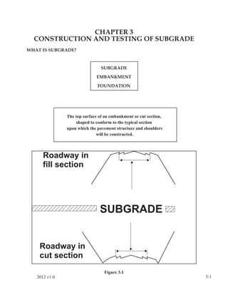
  • 1. CHAPTER 3 CONSTRUCTION AND TESTING OF SUBGRADE WHAT IS SUBGRADE? SUBGRADE EMBANKMENT FOUNDATION The top surface of an embankment or cut section, shaped to conform to the typical section upon which the pavement structure and shoulders will be constructed. Figure 3.1 2012 v1.0 3-1
  • 2. IMPORTANCE OF SUBGRADE Heavy trucks and buses are continually loading our pavements. These loads are transmitted through the pavement to the subgrade. In effect, the loads applied to the surface of the pavement are transmitted through the structure, deforming or otherwise destroying the integrity of the subgrade. How the subgrade is going to react under the application of traffic loads is of great concern. As illustrated in Figure 3.2, how the load gets transferred to the subgrade and how the subgrade can handle that load has a strong influence on the overall quality of the pavement. If the pavement is thin as shown in the right hand sketch, the stress imposed by the traffic load through the pavement is distributed over a small area, making for high stresses on the subgrade. If the subgrade is poorly prepared (improper compaction, excessive moisture, etc.) or has a very low strength (such as with highly plastic clays), the subgrade cannot resist these high stresses and ruts will form which could lead to significant damage to the pavement. If the pavement is thick as shown in the left hand sketch, the stress imposed by the traffic load through the pavement is distributed over a large area, making for low stresses on the subgrade. Even if the subgrade is made up of low strength soils such as the highly plastic clays mentioned above, you can still have a good performing pavement because the stress projected through the pavement is lower than it would be with a thin pavement and if the design is done properly, these stresses should be lower than what can be resisted by the subgrade. It is still important to have the subgrade soils properly compacted when a thick pavement is used because rutting can still take place. As mentioned above, reducing stress can be accomplished by simply building a thicker pavement. This looks great on paper and is practical to a point. But pavement items are very expensive. Optimizing the pavement itself is very important, but there comes a point where this is not practical. Providing a strong subgrade is essential. Increasing the strength of subgrade allows us to use a thinner pavement. Figure 3.2 - Load Distribution Characteristics of Thick Versus Thin Pavement 3-2 2012 v1.0
  • 3. Figure 3.3 A California Bearing Ratio (CBR) test is run on soils to gauge the strength of the subgrade as compared to a dense graded aggregate. CBR is one of the major factors used in pavement design to determine how thick the pavement should be. Since we have chosen a pavement based on certain subgrade conditions, we must have the best subgrade conditions under our pavement for it to perform its job. To understand the impact of CBR (subgrade strength) on the pavement, lets look at some typical CBR values. A clayey soil generally has a low CBR value (less than 8). Sands are more granular and drain better and will generally have CBR values between 15 and 35. Gravel will have the best CBR values, generally 25 and up. That is why it is suggested to save the best material to cap the subgrade. The higher the CBR of foundation soils you have, the less pavement structure is needed, the more economical the design. CBR values are also used as criteria for borrow material. 2012 v1.0 3-3
  • 4. TYPES OF SUBGRADE MATERIALS Types of Subgrade Material • Material in place – soils in a cut section • Imported Material – borrow material and regular excavation material • Treated Material • Material in place or imported material • May be considered in design of the pavement structure • Improves engineering properties of the soil • Provides platform to compact subsequent layers The Specifications list three types of material which are acceptable for use as subgrade. Each type has different characteristics and must be dealt with accordingly. Material in Place - Whenever the roadway will be in a cut section, subgrade will be in original ground. The density of most soils is at approximately 85 to 90 percent of our Standard Proctor density (VTM-1 or VTM-12) in it’s natural state. Soil in this condition falls short of having the strength to support our pavement structure. In order to achieve our desired strength, these soils must be compacted. The specifications require that material in place be scarified to a depth of 6 inches for a distance of 2 feet beyond the proposed edges of pavement on each side. This is illustrated in Figure 3.4 on Page 3-5. This requirement applies to both cut and fill sections. Imported Material - Subgrade material consisting of imported material is called “borrow material”. This material can come from regular excavation from another area in the project, from commercial sources, or from local pits or quarries obtained by the Department or the Contractor. Placement and compaction of borrow material would follow the same procedures and practices that are used when placing and compacting soil taken from a cut site on the project. Treated Material in Place - For some soils, simply scarifying and compacting will not produce the desired strength needed to support our pavement. In these cases it can be very cost effective to stabilize the subgrade with lime, cement, fly ash or a combination thereof. This provides a solid foundation for the remainder of the pavement. Stabilized subgrade provides two very important benefits: Benefits of Soil Stabilization - Becomes part of pavement structure - Improves structural integrity of layers placed above it 3-4 2012 v1.0
  • 5. COMPACTION REQUIREMENTS FOR SUBGRADE Density Requirements for Subgrade 100% Density for top 6 inches Percent +4 Material Minimum % Density 0 - 50 % 100 % 51 - 60 % 95 % 61 - 70 % 90 % Moisture Requirements for Subgrade Optimum moisture ± 20% Why 100% Density at Subgrade • Promotes uniformity of subgrade • Greater density improves strength Where do we obtain 100% Density at Subgrade? Figure 3.4 2012 v1.0 3-5
  • 6. Figure 3.5 Whether subgrade consists of material in place, treated material in place or imported material, it must be compacted to 100% density (95% for soil-lime). Field densities are compared to VTM-1 or VTM-12. When subgrade material contains large quantities of material retained on the No. 4 sieve, use Table 3-1 to determine the minimum required density. Percent Minimum +4 Material Percent Density 0 - 50 100 51 - 60 95 61 - 70 90 Table 3-1 3-6 2012 v1.0
  • 7. SUBGRADE STABILIZATION The top of subgrade, as with other portions of an embankment, can be stabilized by two primary methods: mechanical and chemical. METHODS OF SUBGRADE STABILIZATION Mechanical Chemical Rolling Cement Geotextile Lime Fly Ash Lime-Fly Ash Cement-Lime Salts Mechanical Stabilization Mechanical Stabilization - Rolling Often referred to as Compaction - Density Increases - Permeability Decreases - Compressibility Decreases In the case of mechanical stabilization, rolling is the simplest and most commonly used method. Appendix E details the various types of rollers available and which type roller works best for certain soils. For subgrade stabilization however, the most commonly used rollers are pneumatic, static steel wheel, and vibratory steel wheel. The results of rolling include increasing density, increasing strength, decreasing permeability and decreasing compressibility. Mechanical Stabilization - Rolling Match equipment to soil type Fine-grained soils – clays and silts • Sheepsfoot Roller • Rubber Tire Roller • Smooth Wheel Roller Coarse-grained soils – gravels and sands • Crawler Tractor • Vibratory Roller 2012 v1.0 • Rubber Tire Roller 3-7
  • 8. Mechanical Stabilization – Geosynthetics A method of mechanical stabilization that is gaining popularity throughout the commonwealth is to use Geosynthetics. The types of Geosynthetics that are most likely used for stabilization are geotextiles, geogrids, and geocomposites. - Geotextiles – Consist of synthetic fibers made into flexible, porous fabrics by standard weaving machinery or are matted together in a random nonwoven manner. - Geogrids – Plastics formed into open, gridlike configuration - Geocomposites – A combination of Geosynthetics such as a Geotextile attached to a dimpled plastic sheet used for pavement drainage, or a Geotextile attached to a geogrid. Geotextiles have been used in roadway construction in Virginia since the early 1970’s, primarily in erosion and siltation control. In the 1980’s, the construction industry began using geosynthetics in earth stabilization applications. The primary benefit of using a geotextile is that you get separation between the poor quality subsoil and the better quality backfill material. An additional benefits of using a geotextile or a geogrid is an increased resistance to spreading by means of the reinforcement. Because of this, the Department can save a substantial amount of money by using geosynthetics to “bridge” soft subgrade areas and reduce or eliminate undercutting. The local District Materials Engineer can give guidance as to the types of materials that can be used and where they can be used. Subgrade Stabilization using Geotextiles - Provides separation of soil/aggregate - Provides reinforcement of base - Placed at subgrade elevation - Rolled out and pulled tight – limit wrinkles - Seams connected by 2 foot overlap Geotextiles are the most widely used geosynthetic. In this chapter we will discuss how we use geotextiles at the subgrade and under embankments. The geotextile performs the primary functions of reinforcement and separation when used at the subgrade and on the embankment footprint. Typically the geotextile is placed in the desired area, pulled tight to limit wrinkles, and if at the subgrade, an over lap of 2 feet is provided at the seams. However, to reinforce an embankment, all seams are to be sewn to allow for the tensile stress to be transmitted. It is critical that the correct geotextile is used in the appropriate place, since the properties of various styles will affect the overall performance of the structure. Geogrids are also becoming more widely used in Virginia. While these can be used to reinforce a subgrade, or an undercut, they are most likely to be used to reinforce a slope or embankment foundation. Careful attention must be paid to the specifications or contract documents for geogrid selection and installation. 3-8 2012 v1.0
  • 9. Chemical Stabilization Chemical Stabilization • Cement • Lime • Flyash • Lime & Cement • Salts (Sodium Chloride, Calcium Chloride, Potassium Chloride) In the case of chemical stabilization, the procedure is to add a chemical that reacts with the soil, changes its physical and/or chemical characteristics and forms a more stable material. The most commonly used methods of chemical stabilization of subgrade soils are listed above. These materials are mixed with the subgrade soils and are allowed a curing period to react with the soil and harden. Some of these materials (such as lime, lime-fly ash, and salts) can be mixed with water to form a slurry and are then pressure injected into a soil mass to form a stable structure foundation or to stabilize a landslide. Hydraulic Cement Stabilization Commonly called “soil cement”, hydraulic cement stabilization is the most widely used method of stabilizing soils. The method is acceptable for a wide variety of soils (See Table 3-2). Chemical Stabilization – Soil-Cement • Used in sandy and gravelly soils (10 to 35% fines) • Used in some fine-grained soils with low plasticity • Not used in very coarse sands and gravels • Not used in highly plastic clays • Not used in organic soils Cement is usually added to existing material in place. This is normally done with a self-propelled, self-powered, rotary mixing or tilling machine. The subgrade layer is scarified to the specified depth, cement and water added, and mixed by the same machine in one pass. Other machines which require a separate pass for each operation may be used but are not common. The amount of cement to add to the soil to achieve the desired results depends on the soil type and is determined in the design phase by performing laboratory testing. Typical cement contents are shown in Table 3-2. This amount of cement can be specified either by weight or by volume. PCA recommends specifying the cement content by weight, however VDOT typically specifies the cement by volume since there are fewer field calculations needed to determine application rate. 2012 v1.0 3-9
  • 10. CEMENT REQUIREMENTS (by Soil Type) Usual Range in Cement Requirement Percent by Percent by Soil Type Volume Weight Clean Gravel 5–7 3–5 Clean Sand 7–9 5–8 Dirty Gravel/Sand 7 – 10 5–9 Silt 8 – 12 7 – 12 Clay 10 – 14 10 – 16 Table 3-2 When using cement stabilization, the control necessary to ensure that a quality product is produced consists of the following: FIELD CONTROL OF SOIL CEMENT 1. Application rate 2. Moisture 3. Depth control 4. Compaction 5. Curing Application Rate Cement stabilized subgrade is specified as a percentage of cement per unit volume or by unit weight and a depth of manipulation (i.e. 10% cement by volume, 6” depth - 10% cement by weight, 6” depth). Cement can be applied by either using bag cement or bulk loads with the latter being the most common. The application rate depends on the percentage by volume or weight, depth and width of spread. Application rate can be controlled by either a rate per foot basis or a rate per square foot basis. The following nomographs (Pages 3-11 & 3-12) are used to determine the application rate when the cement content is specified as a percentage of weight. The application rate is determined prior to placement of the cement to ensure that an adequate amount of cement will be spread to achieve the desired percentage of cement. Both the contractor and inspector should be aware of how much cement is to be applied to achieve the desired outcome. 3-10 2012 v1.0
  • 11. PCA Construction Manual – Cement by Weight 2012 v1.0 3-11
  • 13. EXAMPLE #1 Given: The plans call for 10% cement by weight, 6” depth. There are two 12 foot lanes. The base aggregate is to extend 1 ft. beyond the edge of pavement on each side. The width to be treated is 1 ft. beyond the edge of the base stone on each side. The Dry Density of the soil to be treated is 112 lb/ft3. The contractor plans to spread the cement for the entire width in four sections or pulls. The load of cement in question contains 22.5 tons. Question: How many feet of roadway should this load of cement treat? Solution: 24 ft. (Two 12 ft. lanes) + 2 ft. (base aggr.) 2 ft. (beyond base) 28 ft. width of treatment 28 ft. width of treatment ÷ 4 sections (1/4 width) = 7 ft. pulls Use the nomograph on Page 3-14 with 112 lb/ft3 and 10% cement. This yields 10.2 lbs. of cement per cubic foot of compacted soil-cement. Then go to nomograph on page 3-15 with 10.2 lbs. of cement per cubic foot of compacted soil-cement, to 6” depth, and 7’ pull width. This yields 36 lbs. of cement per foot per pull. 22.5 tons X 2000 lbs/ton = 45,000 lbs. on this load. Since the contractor will make four pulls this figure needs to be quartered to 11,250 lbs. per pull. 11,250 lbs./pull ÷ 36 lb/ft = 312.5 ft. per pull. Answer: For the contractor to apply cement at the specified application rate of 10% by weight for 6” depth of treatment; Making four pulls from a 22.5 ton load of cement should cover 312.5 ft. by 28 ft. in width. 2012 v1.0 3-13
  • 14. 3-14 2012 v1.0
  • 15. 2012 v1.0 3-15
  • 16. EXAMPLE #2 Given: The plans call for 12% cement by volume, 8” depth. Width of treatment is 28 feet. The net weight of the cement in the tanker is 22.5 tons. Question: How many feet of roadway should this load of cement treat? Solution: Application Rate = [(WT)(DT)] [(DC)(94)] Where = WT = Width of Treatment in feet DT = Depth of Treatment in feet DC = Design Cement Content (Volume in Decimal Form) 94 = Unit Weight of Cement in lbs/ft3 Example = WT = 28 feet DT = 0.666 feet (8 inches) DC = 0.12 (12% by Volume) Application Rate = [(WT)(DT)] [(DC)(94)] = [(28 ft.) (0.666 ft.)] [(0.12) (94 lbs/ft3)] = [18.648 ft2] [11.28 lbs/ft3] = 210.35 lbs/ft Application Length = Net Weight of Cement Application Rate = 22.5 tons x 2000 lbs/ton 210.35 lbs/ft = 45000 lbs. 210.35 lbs/ft = 214 feet Answer: A load of 22.5 tons of cement applied at the rate of 12% by volume for 8” depth of treatment should cover 214 ft. by 28 ft. in width. 3-16 2012 v1.0
  • 17. Moisture Proper moisture control is crucial with cement treated subgrade. Because of the fine- grained cement, the soil has a tendency to “dry out”. Best results can be obtained when the mixture is brought to optimum or within 20% above optimum of the original soil. The specifications require the mixture have moisture of not less than optimum or more than optimum by 20% above optimum. This is graphically illustrated in Fig. 3.6. Constant moisture checks are needed. Check the soil moisture prior to applying the cement. The Contractor will use this “beginning” moisture to figure how much water to add to get the material to optimum moisture. In most cases water is added during mixing to bring the soil to the optimum moisture content. Check the moisture after the first pass of the mixer. This way the Contractor can add water if necessary before compaction. Moisture checks should also be run periodically while compacting the mixture to ensure that optimum moisture is maintained throughout the rolling operation. During finishing, maintain moisture by lightly sprinkling the surface with water. CHECK MOISTURE … 1. Before applying cement 2. After mixing / before rolling 3. With compaction testing MOISTURE CONTROL (0 to 20% of optimum) (10 to 20% of optimum) Figure 3.6 2012 v1.0 3-17
  • 18. Depth Control Having the proper depth of treatment is one of the most important factors affecting the final product. Deviation from the specified depth either by an increase or decrease has an effect on the strength of the treated material. (see Fig. 3.7 below) As stated earlier, stabilized subgrade is part of the pavement structure. If the treated depth is less than that specified, we are compromising the pavement’s depth. If the treated depth is greater than that specified, the cement will be dispersed throughout a greater volume and the entire course will be weak. The general rule of thumb for soil compaction applies here: 8” of loose soil (after mixing) will compact to 6”. This should be checked. After the material has been compacted and tested for density it must be checked for depth. When material in place is tested the aid of a liquid solution of phenolphthalein in distilled water is needed. This can be obtained from your District Materials Personnel. When the solution comes in contact with cement or lime it turns purple in color. Check the depth of cement by using a pick to dig a hole and, using a medicine dropper, apply the solution to the side of the hole. The purple indicator disappears at the bottom of the cement. A stake placed flat on the ground across the hole and a ruler are used to measure the depth. EFFECTS OF INCORRECT DEPTH If plans called for 6” depth and 10% by volume assuming application rate is correct … too JUST too deep RIGHT shallow YIELDS: 8.5% 10% 12% Figure 3.7 3-18 2012 v1.0
  • 19. Compaction 8” Loose = 6” Compacted 8” 6” COMPACTION CRITERIA - Minimum 100% of maximum theoretical density - Sufficient number of rollers to achieve density within 4 hours after mixing - Any portion on which the density is below the specified density by more than 5 lbs/ft3 shall be removed and replaced - Minimum rate of compaction tests – 1 per ½ mile per width The Specifications require that soil cement be compacted to 100% of the maximum density. Compaction equipment is subject to the approval of the Engineer. A sufficient number of compaction units should be provided to ensure that the specified level of density and the completion of the compaction of the soil cement section is accomplished within 4 hours from the time water is added to the mixture. The minimum rate of compaction testing is one test per ½ mile for each application width or pass. Any portion on which the density is below the specified density more than 5 lb/ft3 shall be removed and replaced. Curing Just as with hydraulic cement concrete, cement stabilized subgrade must be cured to develop the desired strength. Once the grade has been approved the next course may be placed. In order that the grade does not dry out, the specifications require it to be kept moist. This will aid the curing. The contractor may elect to use an asphalt cover material in lieu of moist curing. However, if the next course is not placed within 7 days, it must be protected with an asphalt cover material. 2012 v1.0 3-19
  • 20. When material may be exposed to freezing temperatures during the first 24 hours of curing, the contractor shall protect the stabilized material from freezing for 7 days or cover the soil-cement surface with the next pavement course within 4 hours after the cement stabilization has been finished as specified. Figure 3.8 OTHER SUBGRADE STABILIZATION METHODS Lime Stabilization SOIL LIME Used in fine-grained soils – clays and silts Used in wet soils Not appropriate for non-plastic soils – sands and gravels SOIL LIME Reduces plasticity of soils – lowers PI Provides cementation Helps to “dry” soils Improves strength of soils (CBR) 3-20 2012 v1.0
  • 21. Lime stabilization works very well with fine-grained soils, particularly heavy clays because it changes the plasticity characteristics of the clay. The addition of lime to a wide variety of soils greatly improves its load carrying capacity. It should be noted that although lime can be used with granular soils, you can generally get greater strength gain by using cement for the same money spent to use lime. SOIL LIME - CONSTRUCTION 1. Application rate 2. Scarify and pulverize soil to required depth 3. Spread lime 4. Spray water and mix 5. Cure 6. Final mixing 7. Compaction The application rate of the lime will be shown on the plans or can be as directed by the Engineer (generally the District Materials Engineer). The lime may be applied to the partially pulverized material as a slurry or in dry form. Hydrated lime or quicklime can be used. When quicklime is used in a dry form, it is to be applied at the same rate as hydrated lime. Lime stabilization should be done in stages. In the first stage, the prepared roadbed is scarified to the depth and width required for the stabilized layer. After scarifying, the material is to be partially scarified. The depth of scarification, pulverization and blading should be controlled in such a manner that the surface of the roadbed below the scarified material shall remain undisturbed and conform to the established cross section. Prior to the beginning of stabilization work, material retained on the 3” sieve is to be removed from the roadbed. If quicklime is slaked to produce a slurry, correction factors need to be applied to make sure the proper amount of lime is being used (see Section 306.03 of the specifications for correction factors). Lime applied by slurry generally causes less dust problems than using dry lime. Regardless of the system, the spreading equipment should uniformly distribute the lime without excessive loss. No equipment, except water trucks and equipment used for mixing and spreading, is to travel on the spread lime until mixed. This process generates a lot of heat and there will be a loss of moisture in the soil. Sufficient water should be added to make sure that the moisture content of the mix at time of compaction is not less than the optimum moisture content of the mix nor more than optimum plus 20 percent of optimum. 2012 v1.0 3-21
  • 22. Lime and water are mixed throughout the scarified material as thoroughly as practical by using a disc harrow, scarifier tines and blading, or by other approved methods. Spread the mix over the roadway and seal roll with a steel wheel or pneumatic tire roller to retard loss of moisture and allow to cure. Curing is considered completed when a uniform material is produced in which at least 60 percent of the material (except aggregate particles) passes the No. 4 sieve or 24 hours have lapsed since the beginning of mixing, whichever occurs first. Soil Lime – Cure Cure up to 24 hours or until at least 60% passes #4 sieve Final mixing will take place. If a stationary plant is used to mix the soil and lime, the material can be placed, compacted and finished immediately after mixing. Soil Lime – Compaction • Same compaction equipment • 95% density • Moisture just prior to compaction, optimum to + 20% optimum Unlike soil-cement mixtures, soil-lime mixtures are compacted to a density of 95 percent of the maximum theoretical density of the mixture determined in accordance with VTM-1 or VTM-12. Final rolling is done with a pneumatic tire roller. Final compaction and finishing must be completed within 12 hours after final mixing. After finishing of the treated subgrade, no vehicles (except the water truck) will be permitted on the compacted soil-lime mix for a period of 7 days or until the next layer of the pavement structure is placed, whichever is less, to allow for final curing. During the final curing period, the soil-lime mix is lightly sprinkled with water at frequent intervals to prevent drying of the mix. If at the end of 7 days the contractor has not placed the pavement course, the contractor must place liquid asphalt and a cover of fine aggregate on the mix. Salts Stabilization of soils have been accomplished with salts such as sodium chloride, calcium chloride, or potassium chloride. This method of subgrade treatment has been successful, but the treated material must be covered quickly or the salt will redissolve. Chloride is very expensive and thus is not a very cost effective method of treatment. Rusting of equipment by this method is also a problem. 3-22 2012 v1.0
  • 23. Lime/Fly Ash Fly ash by itself provides no strength gain for soil. However, if lime is added with the fly ash, they will react to provide cementation of the soil. Lime Cement In some eastern areas of the state, lime and cement are used together to stabilize soil. The lime is used to dry the silty sands that are virtually saturated, and then cement is added to improve its strength. It is quite expensive, but sometimes may be proven to be cost effective because you aren’t undercutting a good quality material that can give you good strength if dried and treated with cement. TREATMENT OF UNSUITABLE SUBGRADE MATERIAL When solid rock is encountered at subgrade, the roadbed must be excavated below the elevation shown on the plans and backfilled in accordance with Road and Bridge Standard RU-1 (606.01). This standard is reprinted at the end of this chapter. Other unsuitable materials include saturated material, high plasticity clays, or other low CBR material. These must also be undercut and backfilled with approved material. PROTECTING THE WORK After subgrade is finished and has been checked and approved, it must be maintained. Any deficiencies in compaction, grade or moisture must be corrected before subsequent layers can be placed. If subgrade becomes eroded or distorted prior to placing subsequent layers, it must be scarified, reshaped and recompacted to the original requirements. If subgrade becomes unstable after placing any or all of the pavement, the unstable area must be undercut and reconstructed properly. The above is a specification requirement. Having to go back and re-work areas which have been completed is time consuming and costly. The same procedures for grading to drain with embankments also apply to protecting the work at any stage of construction. TESTING AND INSPECTION OF SUBGRADE After scarifying and compacting, subgrade must be tested for compaction and checked to ensure a typical cross section and uniform grade before subsequent courses can be placed. The minimum rate of density testing for untreated subgrade material in place is one test per 2000 linear feet of roadway (full width). Before pavement items are placed on subgrade, it must be visually checked for soft spots, depressions, etc. Passing compaction tests don’t necessarily mean subgrade is ready for the pavement. Any deficiencies must be corrected prior to placing subsequent layers. 2012 v1.0 3-23
  • 24. OBSTRUCTIONS AT SUBGRADE The materials exposed at subgrade elevation, or in areas that are to receive fill must be visually evaluated to determine if construction operations may proceed. If the materials exposed consist of rock, existing hydraulic cement concrete pavement, existing asphalt concrete pavement or unsuitable materials, these must be handled appropriately. If solid rock is encountered at subgrade elevation, it must be removed to the depth specified in Standard Drawing, RU-1, Standard Method for Undercutting Rock. The reason that the rock must be removed is to provide for a uniform base upon which to place the pavement. If the pavement is placed on a base that provides irregular support, then the pavement may deform in the areas where there is limited support. If existing pavements are encountered, depending on where they are relative to the future subgrade elevation, they are handled differently. It also depends on the type of pavement as to how the materials will be handled. The figures on Pages 3-25 and 3-26 describe what to do. It is important to remember that adequate drainage be maintained and that any excess materials are properly handled. If highly plastic clays, organic materials or very wet materials are encountered at subgrade elevations, these materials must be either removed and replaced or dried out so they can be re-used. The disposition of these types of materials is usually described in the plans. 3-24 2012 v1.0
  • 25. 2012 v1.0 3-25
  • 26. 3-26 2012 v1.0
  • 27. 2012 v1.0 3-27
  • 28. CHAPTER 3 Study Questions 1. is the top surface of the embankment and the foundation for the pavement structure. 2. Subgrade must be scarified for a distance of beyond the proposed edges of pavement to a depth of and recompacted to the original requirements. 3. days after placement of the Cement Stabilized Subgrade the next course of pavement or approved cover material must be applied. 4. True of False. Cement is used with soil or aggregate to make the soil or aggregate more workable. 5. Why is lime used with soil? 6. The tolerance on the optimum moisture content at which aggregate must be compacted is . 7. The tolerance on the optimum moisture content for cement treated subgrade, is . 8. The most common type of geosynthetic used is a . 9. True or False. Sewing of embankment stabilization fabric seams is not required. 10. What is the minimum number of tests required for finished subgrade from Station 453+60 to Station 553+60? 11. Cement Stabilized Subgrade has been placed 48 feet in width from Station 392+20 to Station 550+60 with a paver application width of 12 feet. Determine the number of tests required and the density and moisture requirements. 3-28 2012 v1.0
  • 29. CHAPTER 3 Study Problems 2012 v1.0 3-29
  • 30. 3-30 2012 v1.0
  • 31. Practice Problem 1 Cement Application Rate The plans call for 9.5% cement by weight, 6” depth. There are two 12’ lanes. The base aggregate is to extend 1’ beyond the edge of pavement on each side. The width to be treated is 1’ beyond the edge of the base stone on each side. The Dry Density of the soil to be treated is 103.5 lb/ft3. The contractor plans to spread the cement for the entire width in four sections or pulls. The load of cement in question contains 20.28 tons. How many feet of roadway should this load of cement treat? Show your work! 2012 v1.0 3-31
  • 32. Practice Problem 2 Cement Application Rate The plans call for 6.5% cement by weight, 7” depth. There are two 10’ lanes. The base aggregate is to extend 1 foot beyond the edge of pavement on each side. The width to be treated is 1 foot beyond the edge of the base stone on each side. The Dry Density of the soil to be treated is 115.5 lb/ft3. The contractor plans to spread the cement for the entire width in three sections or pulls. The load of cement in question contains 22.2 tons. How many feet of roadway should this load of cement treat? Show your work! 3-32 2012 v1.0
  • 33. Practice Problem 3 Cement Application Rate The plans call for 12% cement by volume, 6” depth. Width of treatment is 26 feet. The net weight of the cement in the tanker is 23.09 tons. How many feet of roadway should this load of cement treat? Show your work! 2012 v1.0 3-33
  • 34. Practice Problem 4 Cement Application Rate The plans call for 6.5% cement by volume, 6” depth. Width of treatment is 24 feet. The net weight of the cement in the tanker is 22 tons. How many feet of roadway should this load of cement treat? Show your work! 3-34 2012 v1.0