If you've owned a regular radar detector, you know the hassles of setting it up and hiding it from thieves when not in use. You hate the dangling cords, suction cups and Velcro tabs that destroy the elegant contours of your instrument panel.
K40's exclusive "Divide-and-conquer" concept solves all that. Inside the cockpit, separate alert lights and speakers or custom Warning Pod mounts invisibly into your vehicle's instrument cluster. A unique two piece control switch, installed discreetly under the kick panel or in the dash, adjusts the on/off, city/highway, and volume functions.
More than Just Lines on a Map: Best Practices for U.S Bike Routes
1000 2000 Install Guide
1. 2 0 0 0 / 1 0 0 0 M O D E L S
Installation Instructions
& Recommended Pr ocedures
WARNING & BI-COLOR LED(S)
(MODELS: K40-2000/1000)
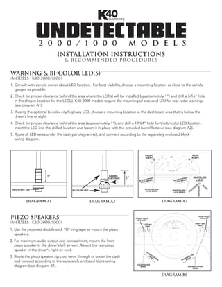
1. Consult with vehicle owner about LED location. For best visibility, choose a mounting location as close to the vehicle
gauges as possible.
2. Check for proper clearance behind the area where the LED(s) will be installed (approximately 1”) and drill a 3/16” hole
in the chosen location for the LED(s). K40-2000 models require the mounting of a second LED for rear radar warnings
(see diagram A1).
3. If using the optional bi-color city/highway LED, choose a mounting location in the dashboard area that is below the
driver's line of sight.
4. Check for proper clearance behind the area (approximately 1”), and drill a 19/64” hole for the bi-color LED location.
Insert the LED into the drilled location and fasten it in place with the provided barrel fastener (see diagram A2).
5. Route all LED wires under the dash per diagram A3, and connect according to the separately enclosed block
wiring diagram.
FRONT REAR
ALERT ALERT
1" BARREL
1" BI-COLOR
FASTENER PPER PPER
K/CO E/CO L.E.D.
BLAC.D. WIRES WHIT . WIRES
L.E L.E.D
R BL
PE
GRAY/SILVER
AC
OP K
/C
RED ALERT LED BI-COLOR LED BLACK/SILVER WHITE/SILVER AY
L.E.D. WIRES L.E.D. WIRES GR
DIAGRAM A1 DIAGRAM A2 DIAGRAM A3
PIEZO SPEAKERS FRONT PIEZO
SPEAKER
REAR PIEZO
SPEAKER
(MODELS: K40-2000/1000) LEFT AIR RIGHT AIR
VENT VENT
1. Use the provided double stick "O" ring tape to mount the piezo
speakers.
2. For maximum audio output and concealment, mount the front
piezo speaker in the driver's left air vent. Mount the rear piezo
speaker in the driver's right air vent. CL
EA
R ER
W /CO
3. Route the piezo speaker zip cord wires through or under the dash IR P
ES PE
ILV
N/S S
OW RE
R BR WI
and connect according to the separately enclosed block wiring
diagram (see diagram B1). CLEAR/SILVER
WIRES BROWN/COPPER
WIRES
DIAGRAM B1
2. WARNING POD(S)
(MODELS: K40-2000P/1000P)
NOTE: For added installation convenience, Warning Pods contain both a warning LED and piezo speaker.
1. Consult with vehicle owner about Pod location. For best
visibility, choose a mounting location as close to the vehi-
FRONT REAR
cle's gauges as possible. WARNING POD WARNING POD
2. Before mounting the Warning Pod(s), clean both the Pod
surface and desired mounting location on the dash with
isopropyl alcohol.
3. Position the Warning Pod(s) on the dash with the provided
double stick "O" ring tape. K40-2000P models require the
mounting of a second Pod for rear radar warnings.
4. Route the black cables from the Warning Pod(s) through or
C
under the dash per diagram C1, and connect according to
B
ER
LE
ER
R
A
O
PP
PP
R
W
/S
CO
O
N
the separately enclosed block wiring diagram.
/C
IL
/S
K/
VE
IL
TE
AC
VE
R
HI
R
BL
W
BLACK/ CLEAR/ WHITE/ BROWN/
SILVER COPPER SILVER COPPER
DIAGRAM C1
FRONT RADAR RECEIVER
(ALL MODELS)
NOTE: All radar receivers can be mounted behind plastic, rubber, or fiberglass up to 1/4” thick. Do not mount
receivers behind metal, carbon fiber, or chromed plastic.
1. Choose a mounting location in
the front of the vehicle that is not
obstructed by any metal, carbon RADAR
RECEIVER
fiber, or chromed plastic. The
radar receiver can be mounted SELF-
TAPPING
horizontally or vertically, provided SCREWS RADAR
RECEIVER
the arrows are pointing forward, METAL
SUPPORT
SELF-
TAPPING
towards the road ahead. SCREWS
2. Mount the radar receiver to the
vehicle's structure using the
supplied screws or wire tires
(see diagram D1). DIAGRAM D1
3. Connect the radar receiver to the 10’ black radar re-
ceiver cable. Align slot on cable plug to the notch on LOCKING RIB
FACTORY
radar receiver socket, slide the locking ring forward over LOCKING GROMMET
the socket, and turn ring clockwise 1/4 turn to engage WINDOW
safety lock (see diagram D2). LOCKING
PIN FRONT
RADAR
RECEIVER
4. Route and affix the radar receiver cable along the inner LOCKING CABLE
RING
fender in the engine compartment to the firewall using
KEY
the provided wire straps. GUIDE KEY WAY
LOCKING
5. Route the radar receiver cable through a factory rubber PIN
BR
ITE
grommet on the firewall and into the passenger com-
OW
GREEN
WH
N
partment (see diagram D3). Connect wires according to
the separately enclosed block wiring diagram.
DIAGRAM D2
DIAGRAM D3
3. REAR RADAR RECEIVER
(MODELS: K40-2000/2000P)
NOTE: All radar receivers can be mounted behind plastic, rubber, or fiberglass up to 1/4” thick. Do not mount
behind metal, carbon fiber, or chromed plastic.
1. Choose a mounting location in the rear of the vehicle that is not
obstructed by any metal, carbon fiber, or chromed plastic. The
radar receiver can be mounted horizontally or vertically, provided
the arrows are pointing to the rear, towards the road behind the
vehicle.
2. Mount the radar receiver to the vehicle's structure using the sup- METAL
SUPPORT
plied screws or wire tires (see diagram E1).
RECEIVER
3. Connect the radar receiver to the 25’ black radar receiver cable.
SCREWS
Align slot on cable plug to the notch on radar receiver socket, slide
the locking ring forward over the socket, and turn ring clockwise REAR RADAR RECEIVER
(BEHIND BUMPER COVER)
1/4 turn to engage safety lock (see diagram E2).
4. Route the rear radar receiver cable into the trunk through a DIAGRAM E1
factory grommet.
LOCKING RIB
5. If a factory grommet is not available, use the provided strain relief:
LOCKING
a. Choose a location in the trunk compartment as close to the WINDOW
radar receiver as possible. LOCKING
PIN
b. Drill a 1/2” hole into the chosen location for the strain relief.
LOCKING
RING
KEY
Do not drill into the trunk until you know GUIDE KEY WAY
CAUTION! what is on both sides of the drilling area. LOCKING
Watch for cables, spare tires, and gas tank. PIN
c. Install the strain relief and tighten the mounting nut securely
(see diagram E3) DIAGRAM E2
d. Route the rear radar receiver cable through the strain relief,
leaving a little slack in the receiver cable. ROUTE THROUGH VEHICLE
MOUNTING NUT
e. Tighten the waterproof gasket nut to create a water proof seal. METAL
TRUNK
6. Route the rear radar receiver cable through the trunk, into the WATERPROOF
GASKET MATERIAL
passenger compartment along the driver's side, and under the
dash. Connect wires according separately enclosed block TO RADAR DETECTOR
wiring diagram.
DIAGRAM E3
VOLUME CONTROL MODULE
(all MODELS)
1. Choose a mounting location that's accessible to the driver in the dashboard area
or in the vehicle's center console that will not obstruct or block any moving parts.
ON-OFF/
FILTER
ADJUSTMENT
Before drilling, make sure there is enough clearance for the VOLUME
CAUTION! Volume Control Module behind the chosen mounting location CONTROL
MODULE
(approximately 3 1/4”).
2. Drill a 5/16” hole. MOUNTING
NUTS
3. Mount the Volume Control Module with the lock washer and nuts, and push the LOCK ON-OFF/FILTER
WASHER ADJUSTMENT
filter and volume adjustment knobs onto the module shaft (see diagram F1). VOLUME
KNOB
CONTROL
KNOB
4. Route the Volume Control Module cable under the dash and connect wires
according to the separately enclosed block wiring diagram. DIAGRAM F1