Introduction to Navigation Systems
•Als PPT, PDF herunterladen•
8 gefällt mir•6,507 views


Empfohlen
Weitere ähnliche Inhalte
Was ist angesagt?
Was ist angesagt? (20)
Ähnlich wie Introduction to Navigation Systems
Ähnlich wie Introduction to Navigation Systems (20)
Introduction to Navigation Systems
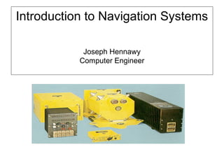
- 1. Introduction to Navigation Systems Joseph Hennawy Computer Engineer
- 2. Table of Contents History of Navigation Systems. Accelerometer Sensors Technologies (Body Speed & Acceleration). Gyroscope Sensors Technologies (Body Attitude). Navigation Coordinate Systems. GEODESY & DATUMS. INS Systems Error Analysis. GPS/INS Systems. Current Navigation Systems The Future of Navigation Technologies.
- 3. Inertial Navigation History Inertial Guidance System of SAGEM used in the Air-Surface Medium- range missile
- 7. Jean Bernard Léon Foucault Originator of the Foucault pendulum 1819-68
- 9. Mechanical Dead Reckoning Computer: Early 20th century
- 10. SG-66 Guidance System for the V-2 (1944)
- 11. Charles Stark Draper Gyroscopic Apparatus - Spinning Gyroscope Born 2 October 1901 Died 25 July 1987
- 12. First Successful All-Inertial Navigator (1954)
- 13. Professor Arnold Nordiseck Holding Early Electrostatically Suspended Gyroscope (1959)
- 14. Honeywell Advertisement for Electrostatically Suspended Gyroscope, 1962
- 15. Warren Macek of Sperry Circa 1963 Demonstrating the Ring Laser Gyro Concept
- 16. Laser Gyro
- 17. Tactical Grade Closed-Loop FOG • Tactical FOG IMU funded by USAF • HG1800 FOG IMU is pin-for-pin compatible with HG1700 RLG IMU • Goals: 1 deg/hour Gyro Error 1 milli-G Accel Error • Housing identical to HG1700 IMU <35 cubic inches
- 18. INERTIAL NAVIGATION HISTORICAL EVENTS • Newton’s second law: circa 1688 • Leon Foucalt: demonstration of earth rotation using a gyroscope 1852 Greek: “gyro”--rotation; “skopein”--to see • G. Trouve: Mechanical gyroscope with electric motor 1865 • Anschutz: First gyrocompass 1904 • Schuler: Pendulum/gyroscope unaffected by ship/course/speed 1908 • Boykow(Austria): Mathematics of inertial navigation 1938 • Peenemunde Group(Germany): First operating inertial guidance on V2 1942 • Autonetics: Under the ice Nautilus crossing of North Pole 1958 • Autonetics: Transcontinental purely inertial flight 1958 • AC-Delco, Litton, Honeywell, Sperry, Singer-Kearfott, Sagerm(French): 1960’s Military bombers, ships, fighter, ballistic missiles • MIT/Delco: Apollo guidance system 1969 • Honeywell: Electrically suspended gyro navigator 1967 • Sperry: First ring laser gyro 1963 [ ]IVm dt d F =
- 19. INERTIAL NAVIGATION HISTORICAL EVENTS(2) •Various: First inertial navigation systems in commercial aircraft late 60’s • RLG: based strap down systems on commercial aircraft early 80’s • RLG: based strapdown systems in military mid 80’s • First Fiber Optic Gyro Based inertial systems early 90’s • First Embedded GPS-INS systems early 90’s • Low cost tactical microelectromechanical sensors(MEMS) NOW
- 20. Accelerometers
- 23. FORCER VERTICAL PIVOT PICKOFF AMPLIFIER Simple Pendulum Accelerometer
- 24. Torque Balance Pendulous Accelerometer Schematic
- 25. EMERGING ACCELEROMETER TECHNOLOGY APPLICATIONS
- 30. Physical •Weight 1.54 pounds (700 grams) •Size 3.5 inches (8.9 cm) diameter by 3.35 inches (8.5 cm) high •Power 10 watts steady-state (nominal) •Cooling Conduction to mounting plate •Mounting 4 mounting bolts – M4 Activation Time 0.8 sec (5 sec to full accuracy) Performance – Gyro •Bias Repeatability 1°/hr to 10°/hr 1σ •Random Walk 0.04 to 0.1°/√hr power spectral density (PSD) level •Scale Factor Stability 100 ppm 1σ •Bias Variation 0.35°/hr 1σ with 100-second correlation time •Nonorthogonality 20 arcsec 1σ •Bandwidth > 500 Hz Performance – Accelerometer •Bias Repeatability 200 µg to 1 milli-g, 1σ •Scale Factor Stability 300 ppm 1σ •Vibration Sensitivity 17 µg/g2 1σ •Bias Variation 50 µg 1σ with 60-second correlation time •Nonorthogonality 20 arcsec 1σ •White Noise 50 µg /√Hz PSD level •Bandwidth > 500 Hz Operating Range •Angular Rate ±1000°/sec •Angular Acceleration ±100,000°/sec/sec •Acceleration ±40g •Velocity Quantization 0.00169 fps •Angular Attitude Unlimited Reliability (predicted) 23,345 hours MTBF (30°C missile launch environment) Input/Output RS-485 Serial Data Bus (SDLC) Data Latency < 1msec Environmental •Temperature -54°C to +85°C operating •Vibration 11.9g rms – performance 17.9g rms – endurance •Shock 90G, ms terminal sawtooth Summary of Ln-200 IMU Characteristics
- 31. Accelerometer Name $2K(1) Part of System Name $2Ksystem(1) Where Found IMU Performance vs. Cost Velocity Random Walk 0.60 (meters/sec)/√(rt-hr) Bias 1000 micro-g Misalignment 412 arcsec Scale Factor 500 ppm Second Order Scale Factor Non-Linearity 60 micro-g/g2 Additional Terms Notes
- 32. Accelerometer Name $20K Part of System Name $20K Where Found IMU Performance vs. Cost Velocity Random Walk 0.03 (meters/sec)/√(rt-hr) Bias 100 micro-g Misalignment 10.3 arcsec Scale Factor 10 ppm Second Order Scale Factor Non-Linearity 3 micro-g/g2 Additional Terms Notes
- 33. Velocity Random Walk 0.0003 (meters/sec)/√(rt-hr) Bias 100 micro-g Misalignment 3 arcsec Scale Factor 100 ppm Second Order Scale Factor Non-Linearity 0.5 micro-g/g2 Additional Terms Notes Accelerometer Name $100K Part of System Name $100K Where Found IMU Performance vs. Cost
- 34. Gyroscopes
- 35. INERTIAL ROTATION SENSOR TECHNOLOGY E;CoursesGyros
- 37. INERTIAL SENSOR APPLICATION 1 5 25 125 625 3125 1e-005 0.0001 0.001 0.01 0.1 1 10 WEIGHT SENSORPERFORMANCE(deg/hr) TACTICAL MISSILES GBI / ASAT RV MEDIUM ACCURACY AIRCRAFT COMMERCIAL AIRCRAFT HIGH ACCURACY AIRCRAFT ICBMSDI POINTING SURFACE SHIP SUB
- 38. Inertial Sensor Technology Comparison Inertial Acronym Definitions ESG Electrostatic Gyro FOG – Fiber Optic Gyro HRG – Hemispherical Resonator Gyro MS – Multisensor MEMS – Micromachined Electromechanical Sensor QRS – Quartz Rate Sensor RLG – Ring Laser Gyro Inertial Acronym Definitions ESG Electrostatic Gyro FOG – Fiber Optic Gyro HRG – Hemispherical Resonator Gyro MS – Multisensor MEMS – Micromachined Electromechanical Sensor QRS – Quartz Rate Sensor RLG – Ring Laser Gyro ESG RLG FOG MS QRS HRG MEMS G yroD rift (deg/hr) Submarines Strategic MX Surface Ships Aircraft Cruise Missles UAVs Precision Guided Munitions (PGM) SCUD-B NO-DONG Unguided GGP FOG EGI SLAM-ER SLAM F-18 TLAM JDAM AGM-L30 EKGM All sensor perf ranges are estimates based on available information All sensor perf ranges are estimates based on available information
- 39. Honeywell Gyro Technology Heritage 1920 1960 1970 1980 2000 202020101990 Iron Gyros Optical Gyros MEMS Optical Gyros Ring Laser Gyro Fiber Optic Gyro Digital Output Moderate Cost Iron Gyros Spinning Wheel Analog Output High Cost MEMS Gyros Silicon Sensor Analog or Digital Output Low Cost World’s first application gyros invented by Elmer Sperry
- 40. IMU Product Evolution Overview RLG FOG MEMS • EGI • GGP • Future • MAPS • PSN Growth • Digital Laser Gyro • HG1700 • HG1800 • HG1900 - in production - developmental - in development Tactical Grade IMUs Navigation Grade Systems and Components EGI Embedded GPS Inertial Integrated System - aircraft, et al MAPS Modular Azimuth & Positioning System - surface vehicles GGP GPS Guidance Package - host of DoD platforms PSN Precision Strike Navigator - precision guided munitions
- 41. Rate Gyro Principles and Designs Type Principle Rotor 1 and 2 2 1 Constancy of Angular Momentum Sagnac Effect 1 1 Preservation of Plane Vibration 1 Degrees of Freedom Design Vibration Optical Hemispherical Resonant Ring Laser. Fibre Optic. Rigid Rotors. Dry Tuned. Nuclear Resonant. Example Etak Hitachi Andrews Murada Delco Draper Bosch
- 42. CURRENT GYRO TECHNOLOGY APPLICATIONS
- 43. Sagnac Effect Active Approach Passive Approach RING LASER FOG INTERFEROMETER OPTICAL GYRO TECHNOLOGIES ∆ƒ = (4Α/λΡ)Ω ∆Φ = (8πΝΑ/λ )Ωc
- 44. Suitability of RLG for Strapdown •Wide Dynamic Measuring Range •Direct Digital Output •Excellent scale factoring Linearity and Repeatability •Excellent Bias Repeatability •Rapid Reaction •No G Sensitivity
- 45. GG 1320 Digital Ring Laser Gyro • Characteristics — < 5.5 cubic inches — < 1 lb — < 2.5 watts — DC power in (+ 15 and +5 Vdc) — Compensated serial digital data output — No external support electronics — All high voltages self-contained — Built on proven RLG technology (> 60,000 RLGs delivered) — Proven mechanical dither • Demonstrated better than 1.0 nmi / hr performance — Low random walk — Excellent scale factor stability — Superb bias stability — No turn-on bias transients — Low magnetic sensitivity Laser Block in full-scale production (900 gyros in 1992, 1300 in 1993, 1400 in 1994)
- 46. Honeywell Ring Laser Gyros (RLGs)
- 47. Ring Laser Gyro Operation
- 48. The Fiber Optic Gyro • Consists of: 1. Semiconductor laser diode as light source. 2. Beam splitter. 3. Coil of optical fiber. 4. Photodetector The Fiber Optic Gyro (FOG) measures rotation by analyzing the phase shift of light caused by the signac effect
- 49. Tactical Grade Closed-Loop FOG• Tactical FOG IMU funded by USAF • HG1800 FOG IMU is pin-for-pin compatible with HG1700 RLG IMU • Goals: 1 deg/hour Gyro Error 1 milli-G Accel Error • Housing identical to HG1700 IMU <35 cubic inches
- 50. Types/Characteristic Applications Ex. Manufacturer Accuracy (deg/hr) Maturity Cable Length (meters) Commercial Grade Automotive, Camera Andrews 100 Present 100 Tactical Grade Attitude/Hdg references; Short-term inertial (min) Litton 200, Honeywell 1 Present 200 Avionic Grade Aircraft & Cruise missile inertial Eg GGP (GPS Guidance Package) Honeywell & Litton .01 - .1 Within next year or two 1000 Strategic Grade Long-term ship inertial Honeywell .00001 Maybe within 5 – 10 years in fleet 5000 - 10000 Quick-Look FOG Status
- 51. SAGNAC Effect (Phase Shift Measured in Nano Radians) Computer Maintains Spatial Reference Uses Large Coil LD Product (5 Km Fiber) Rugged, High Shock Resistance No Precision Machining Typical High-performance IFOG GYRO ELECTRONICS PUMP LASER WDM Erbium doped fiber LIGHT SOURCE IOC COUPLER X XX X X DET FIBER COIL ESG Spinner Assembly ROTOR TECHNOLOGY DIFFERENCESTECHNOLOGY DIFFERENCES Spinning Mass (3600 RPS) Rotor Maintains Spatial Reference Small Size of Rotating Element 1 cm Rotor) Not Rugged, Susceptible to Rotor Crashes Expensive Technology, Precision Machining Ω=∆Φ c NA λ π8
- 52. IMU Product Evolution Summary • RLG IMUs and RLG systems are a growth industry with proven track records in the field • FOG Inertial Systems striving to be lower price than comparable RLG-based systems • MEMS gyros offer the lowest price, smallest size, and lowest power for a tactical IMU • MEMS gyro performance will improve to 1 deg/hr in the next few years; ManTech programs will enable affordable MEMS IMUs in quantities
- 54. Coordinate Frames AXIS 1 AXIS 2 AXIS 3 Inertial(I) (vernal equinox (in equatorial plane) (polar) Aries) ECEF(E) (through (in equatorial Greenwich) plane) Local Level (north)(in meridian (East) (down) North(N) plane) [ ]3GHA ↓ Aˆ Bˆ Pˆ [ ]3 22 - LoL − ↓ π mGˆ mG ′ Pˆ Nˆ Eˆ Dˆ [ ]3α- ↓
- 55. AXIS 1 AXIS 2 AXIS 3 Wander(WA) (α counterclockwise (α counterclockwise from north) from east) (α chosen such that ) Body (point to bow in (point to starboard (deck to keel) deck plane) in deck plane) Train gunsight(T) (out through gun barrel) don’t care don’t care Coordinate Frames cont’d owBˆ tbdSˆ kDˆ LD ie WA IE sinˆ ω−=•Ω DW ˆˆ =VˆUˆ [ ] [ ] [ ]321 HPR ↓ Gˆ [ ] [ ]32 AzElv ↓ NOTE: Names, ordering of axes, ordering of rotations are not universally accepted. They are conventions and definition
- 56. Coordinate Systems Use Navigation quantities, eg, Position, Velocity, Acceleration, Jerk…. are three dimensional vectors and must, when quantified, be expressed with respect to a reference frame (aka) coordinate system. Likewise navigation measurements, eg distances and angles are made with respect to origins and axes of a coordinate system. Va = = (for example) 5 10 14 V1 a V2 a V3 a Meters/secExample: Three scalar elements of velocity vector wrt a coordinate frame.
- 57. GEODESY, DATUMS
- 58. Conceptual Reasons for Studying Geodesy • Three main reasons for studying Geodesy/Astronomy related to inertial navigation: 1.Understanding the meaning of inertial coordinate frame. 2.Knowing gravitational attraction. 3.Knowing the shape of the earth to determine Latitude, Longitude , and Height from ECEF position.
- 59. The Ellipsoid of Rotation Z P P’ Equatorial Plane a a F O F’ b X a a 22 ba + 12 2 2 2 =+ b Z a X
- 60. Shape of the Earth
- 61. WGS-84 & WGS-72 Defining Parameters For WGS-84 Ellipsoid
- 62. WGS-84 Derived Geometric Constants CONSTANT NOTATION VALUE Flattening(ellipticity) f 1/298.257223563 Semiminor Axis b 6356752.3142m First Eccentricity e 0.0818191908426 First Eccentrity Squared e 2 0.00669437999013 Polar Radius of Curvature c 6399593.6258m Axis Ratio b/a 0.996647189335m Mean Radius of Semiaxis R1 6371008.7714m Equal Area Sphere Radius R2 6371007.1809m Equal Volume Sphere Radius R3 6371000.7900 First Eccentricity Squared= (a2 -b2 )/a2
- 63. Different datums may use different ellipsoids. Datums may also differ by the location of the center and orientation of the ellipsoid.
- 64. Simply put, a datum is the mathematical model of the Earth we use to calculate the coordinates on any map, chart, or survey system. All coordinates reference some particular set of numbers for the size and shape of the Earth. The problem for warfighters is that many countries use their own datum when they make their maps and surveys--what we call local datums. Other nations' maps often use coordinates computed assuming the Earth is a completely different size and shape from what the Department of Defense uses, but we have to be ready to fight around the world. US forces now use datum called World Geodetic System 1984, or WGS 84. The National Imagery and Mapping Agency (NIMA) produces all for its new maps with this system. Unfortunately, we reprint many of our maps from products made by allied countries that use local datums. Our old maps were made on several different local datums, or sometimes WGS 72 (maps using this datum were often printed "World Geodetic System" with no year identification). So the old maps we're reproducing, and the foreign ones we reprint, might use those other datums. WHAT’S A DATUM?
- 66. Gravity Disturbance Effects On INS
- 67. TLV = True Local Vertical Perpendicular to Geoid Actual Gravity Vector Astronomic Vertical REV = Reference-Ellipsoid Vertical Perpendicular to Reference Ellipsoid Theoretical Gravity Vector Geodetic Vertical Geodetic Latitude Surface of the Earth Dynamic Sea Level Surface of Reference Ellipsoid Surface of Geoid Gravity Anomaly Deflection of the Vertical Astronomic Latitude TLV REV N SST N = Surface of Geoid - Surface of Ellipsoid SST = Sea Surface Topography Figure 1. Simplified Depiction of Gravity Quantities E:CoursesGeophysical Navigation
- 68. APPROACHES TO GRAVITY COMPENSATION STORED MAP APPROACH PATROL AND PRELAUNCH PHASE USE DEFLECTION/GEOD MAPS TARGET OFFSETS USED FOR INFLIGHT EFFECTS COMPUTED FROM A COMBINATION OF GLOBAL/LONG WAVELENTH GRAVITY MODELS AND HIGH FREQUENCY DATA MAPS REAL-TIME COMPENSATION GRAVITY GRADIOMETER/GRAVIMETER MAY BE USED TO LIMIT GRAVITY-INDUCED NAVIGATION ERRORS LAUNCH POINT MEASUREMENTS MAY BE USED TO REDUCE INFLIGHT EFFECTS 6/10/99
- 69. Gravity Compensation Techniques GRAVITY COMPENSATON EMBODIES • MAP UTILIZATION/INTERPOLATION AND/OR • REAL-TIME MEASUREMENTS AND • SYSTEM INTEGRATION FUNDAMENTAL ELEMENTS OPTIMAL ESTIMATES OF NAV QUANTITIES NAVAIDS INS GRAVIMETER/ GRADIOMETER STORED GRAVITY MAP SYSTEM INTEGRATION ESTIMATOR + +
- 71. Causes of Inertial Navigation Errors • Initial Conditions – An inertial needs three dimensional position, velocity, and attitude (theoretically wrt the inertial coordinate system, but practically wrt a local coordinate system). – For self initialization, these initial condition errors (particularly initial attitude errors) can be caused by sensor errors. – Initial position and velocity often obtained from GPS • Sensor Errors – Gyro and Accelerometer Errors • Bias, Scale factor, Cross axis sensitivities, input axis misalignments, environmental sensitivities
- 72. Causes of Inertial Navigation Errors (cont’d) • Inertial Sensor Assembly Misalignments – Each sensors orientation may be misaligned – In general, only one accelerometer input axis can arbitrarily be taken to be correct • Environmental Effects – Gravity Disturbance Errors • Vertical Deflection for horizontal loops • Gravity anomaly for vertical loop • Aiding Sensor Effects – Errors in altimeter either due to instrument or environment; similarly for EM Log or Doppler aiding • Other – Generally small digital data processing (coning and sculling) and timing errors – Latency, synchro conversion, vibration
- 73. GPS/INS Systems
- 75. Inertial Navigation System Aiding Sources Optimal Processor Corrected Navigation Output (Includes Models of INS errors, aiding errors, and motion models) Non-Complementary Navigation Integration Methodology * * Branches represent potentially individual accels. or gyro. outputs
- 76. Inertial Navigation System Aiding Sources Inertial Error Estimates Corrected Inertial Outputs Kalman Filter+ - Inertial + Aiding errors errors True navigation + aiding errors Standard Complementary Filter Methodology in Feedback Configuration
- 77. Loosely Coupled GPS/INS Integration ArchitectureRF / IF / A/D MULTI-CHIP CORELATOR CARRIER DISCRIMINATOR 90° I & D IE IP QE QL IL QP } L1 L2 I Q (1000 Hz) IMU KALMAN FILTER MEASUREMENT PROCESSING KALMAN FILTER Σ NAVIGATION EQUATIONS (CHIP/SEC) (50 Hz) (CYC/SEC) (50 Hz) ρ (1 Hz) ρ (1 Hz) . PVT (1 Hz)∆θ,∆υ PVAtt (1 Hz) LOS VELOCITY AIDING (50 Hz) INERTIAL SYSTEM PROCESSING 1 of N GPS RCVR CHANNELS GPS RCVR PROCESSING + - GPS NAV PROCESSING (256 HZ) MEASUREMENT PROCESSING CODE NCO CARRIER NCO KFILTER FILTER K NAVIGATION EQUATIONS CODE GENERATOR CODE DISCRIMINATOR ΣΣ LOS PROJECTION + - Σ CARR. NCO BIAS (1 Hz) CODE NCO BIAS (1 Hz) E:CoursesGPS[10] GPS-INS
- 78. Tightly Coupled GPS/INS Integration ArchitectureRF / IF / A/D MULTI-CHIP CORELATOR CARRIER DISCRIMINATOR 90° I & D IE IP QE QL IL QP } L1 L2 I Q (1000 Hz) IMU (CHIP/SEC) (50 Hz) (CYC/SEC) (50 Hz) ρ (1 Hz) ρ (1 Hz) . PVT (1 Hz) ∆θ,∆υ PVAtt (1 Hz) LOS VELOCITY AIDING (50 Hz) INERTIAL SENSOR PROCESSING 1 of N GPS RCVR CHANNELS GPS RCVR PROCESSING GPS NAV PROCESSING (256 HZ) CODE NCO CARRIER NCO KFILTER FILTER K MEASUREMENT PROCESSING CODE GENERATOR CODE DISCRIMINATOR ΣΣ LOS PROJECTION + - Σ CARR. NCO BIAS (1 Hz) CODE NCO BIAS (1 Hz) NAVIGATION EQUATIONS KALMAN FILTER PVAtt PV E:CoursesGPS[10] GPS-INS
- 79. Intimately Coupled GPS/INS Integration Architecture RF / IF / A/D MULTI-CHIP CORELATOR CARRIER DISCRIMINATOR 90° I & D IE IP QE QL IL QP } L1 L2 I Q (1000 Hz) IMU (CHIP/SEC) (50 Hz) (CYC/SEC) (50 Hz) PVT (1 Hz) ∆θ,∆υ PVAtt (1 Hz)INERTIAL SENSOR PROCESSING 1 of N GPS RCVR CHANNELS GPS RCVR/NAV PROCESSING (256 HZ) CODE GENERATOR CODE DISCRIMINATOR LOS PROJECTION + - Σ NAVIGATION EQUATIONS KALMAN FILTER FILTER FILTER CARRIER NCO CODE NCO ∆ρ, ∆ρ (1 Hz) . PV (1 Hz) T (100 Hz) E:CoursesGPS[10] GPS-INS
- 84. H-764G Embedded GPS/INS H-764G Features • Small size: 7.0”H x 7.0”W x 9.8”L • Light weight: 18 lbs* • Low power: < 40 watts* • High MTBF: > 6,500 hours* • GPS/INS and two expansion slots in one small package • Single i960 Microprocessor • Mature, High-Performance Inertial Sensors • 15-year Inertial Calibration Interval • Collins GPS receiver Module • Flight-Proven Ada Software • Turn-Key System Missionization * Will vary depending upon how the expansion slots are populated
- 87. Some Inertial Navigation Systems
- 88. vendor units model HG1900 HG1920 comments volume 16 7.4 in³ Length/Diameter in Width in Depth in mass 0.45 kg power 3 w temperature range -55 to +85 ºC vibration shock 10000 g update rate 100 Hz range 20 g bias 1 .6-6.4 mg scale factor 300 84-2700 ppm nonlinearity 500 200 ppm resolution µg noise mg/√Hz bandwidth Hz random walk .19-.17 m/s/√hr range 1440 º/sec bias 30 09-76 º/hr scale factor 150 91-524 ppm nonlinearity ppm resolution º/hr noise deg/sec bandwidth Hz random walk 0.1 .02-.17 º/√hr data source gyro http://content.honeywell.com/ds Honeywell/Draper imu accelerometer Honeywell/Draper
- 89. vendor units model LN-200 comments volume 32.2 in³ Length/Diameter 3.5 in Width in Depth 3.35 in mass 0.7 kg power 10 w temperature range -54 to 85 ºC vibration 18 g rms shock 90 g update rate Hz range 40 g bias 1 mg scale factor 300 ppm nonlinearity ppm resolution µg noise mg/√Hz bandwidth Hz random walk 0.012 m/s/√hr range 1000 º/sec bias 10 º/hr scale factor 100 ppm nonlinearity ppm resolution º/hr noise deg/sec bandwidth 500 Hz random walk 0.1 º/√hr data source gyro imu Northrup-Grumman accelerometer Northrup-Grumman
- 90. vendor units model SiLMU01 comments volume 6.1 in³ Length/Diameter 2.36 in Width in Depth 1.79 in mass 0.26 kg power 5 w temperature range -40 to +72 operating ºC vibration shock 100 11 ms, .5 sine g update rate Hz range 50 ± g bias 2 1 σ mg scale factor 2000 1 σ ppm nonlinearity 1500 ppm resolution µg noise 5 mg rms in band mg/√Hz bandwidth 75 Hz random walk 1 m/s/√hr range 1000 ± º/sec bias 100 º/hr scale factor 400 accuracy ppm nonlinearity 100 ppm resolution º/hr noise 0.5 rms inband deg/sec bandwidth 75 Hz random walk 1 º/√hr data source http://www.baesystems- BAE imu accelerometer gyro BAE
- 92. • The AN/WSN-7 was designed as a form, fit, and function replacement for the AN/WSN- 1, and -5 for installation on DDG 51, CG 47, CV, CVN, LHA 1 and LHD 1 Class platforms. • The AN/WSN-7A was designed as a form, fit, and function replacement for the AN/WSN-3 on SSN688 Class platforms. • Provides attitude (roll, pitch, and heading), position, and velocity data to ship system users. WSN-7 Information Courtesy Spawar Systems Center, Norfork (Carvil, Galloway)
- 93. CN-1695/WSN-7(V) CN-1696/WSN-7(V) CN-1697/WSN-7(V) Ring Laser Gyro Navigator MX-11681/WSN Inertial Measuring Unit (Inside Cabinet) IP-1747/WSN Display Unit, Control Equipment AN/WSN-7(V) 1/2/3 RLGN Courtesy Spawar Systems Center, Norfork (Carvil, Galloway)
- 94. Install Schedule SHIP CLASS FY02 FY03 FY04 FY05 FY06 FY07 TO COMPLETE CG 47 CG 48 CG 49 DDG 51 DDG 51 DDG 61 DDG 53 DDG 65 DDG 56 DDG 73 DDG 59 DDG 74 DDG 52 DD 963 LHA LHA 5 LHA 3 LHA 1 LHD LHD 4 LHD 1 LHD 2 LHD 3 LHD 6 AGF/LCC LCC 19 LCC 20 CV/CVN CVN 65 DDG DDG 93 DDG 94 DDG 95 DDG 97 DDG 102 DDG 103 DDG 104 CVN CVN 67 LHD LHD 8 TOTAL SHIPS 18 7 2 4 OPNSCN
- 95. CD-132/WSN-7A(V) CD-133/WSN-7A(V) Control Unit, Electronic IP-1747/WSN Display Unit, Control CY-8827/WSN-7A(A) Enclosure Assembly, Inertial Measuring Unit MX-11681/WSN Inertial Measuring Unit MX-11682/WSN-7A(V) Support, Electronics Unit MX-11682/WSN-7A(V) Support, Electronics Unit IP-1746/WSN Display Unit, Secondary Control IP-1747/WSN Display Unit, Control Equipment (Cont.) AN/WSN-7A(V) Red/Green RLGN Courtesy Spawar Systems Center, Norfork (Carvil, Galloway)
- 96. Install Schedule (Cont.) SHIP CLASS FY02 FY03 FY04 FY05 FY06 FY07 TO COMPLETE SSN 688 SSN 690 SSN 763 SSN 719 SSN 767 SSN 721 SSN 768 SSN 722 SSN 771 SSN 754 SSN 772 SSN 756 SSN 701 SSN 757 SSN 760 SSN 713 SSN 715 SSN 709 SSN 715 SSN 752 SSN 756 SSN 761 SSN 764 SSN 698 SNN 699 SSN 720 SSN 769 SSN 21 SSN 21 SSN 22 SSN 21 SSN 774 SSN 778 SSN 779 SSN 780 SSN 784 SSN 782 SSN 783 SSN 784 SSN 785 SSN 786 thru SSN 803 SSGN SSGN 726 SSGN 728 SSGN 727 SSGN 729 TOTAL SHIPS 11 3 7 11 5 3 18 OPNSCN
- 97. Evolution of Inertial Navigation 3-Axis Gyro Chip 3-Axis Accelerometer Chip
- 99. Evolution of Inertial Navigation Technology • Size ,cost,power of Inertial Systems greatly reduced by technology developments • MEMS Technology promises the next major step in Inertial System evolution Litton SiGyTM S/N#0004 FPGA Gimbaled Technology Strapdown Technology Ring Laser Technology Fiber Optic Technology MEMS Technology
- 100. Low Cost Guidance and Navigation • Low Cost Guidance Package enables cost effective precise positioning to be embedded in low value, high volume quantity systems GPS Low Cost Guidance and Navigation Package MEMS Inertial Sensors DSP’s Processors Electronics Applications • Air/Ground Manned /Unmanned Platforms • Guided Rockets • Guided Munitions • Soldier Man Pack • Re-supply Vehicles • ……. • …. • ..
- 101. 2000 200320022001 LN 205G ATK SAASM GPS •Leveraging LN 200 series development reduces MEMS time-to-market LN 205 LN 200 IMU LN 300 LN 300GLitton SiAcTM S/N#0001 Litton SiAcTM S/N #0001 Litton SiAcTM S/N#0001 Litton SiGyTM S/N #0001 Litton SiGyTM S/N#0004 ANALOG DEVICES ANALOG DEVICES ANALOG DEVICES ANALOG DEVICES Digital Asic Analog Asic LN 200G IMU LN300 /LN 200 MEMS INS/GPS Roadmap
- 102. The Future • Over the next 3 to 5 years, the applicability of MEMS for high-g tactical applications will be conclusively demonstrated. • From 5 to 10 years, the insertion of high- volume production MEMS IMUs and INS/GPS into tactical systems will occur at an ever- increasing rate. • The realization of 3 gyros on a chip and 3 accelerometers on a chip, represents the next order-of-magnitude size reduction. • Commercial applications will exploit the development MEMS technology into quantities of billions. 3-Axis Gyro Chip 3-Axis Accelerometer Chip