Weld discountinuitie
•Als PPT, PDF herunterladen•
12 gefällt mir•3,405 views

WELD DISCOUNTINUITESS

Empfohlen
Weitere ähnliche Inhalte
Was ist angesagt?
Was ist angesagt? (20)
Andere mochten auch
Andere mochten auch (15)
Ähnlich wie Weld discountinuitie
Ähnlich wie Weld discountinuitie (20)
Mehr von Jithu John
Kürzlich hochgeladen
Kürzlich hochgeladen (20)
Weld discountinuitie
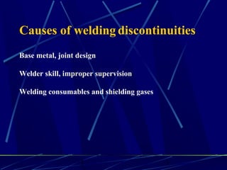
- 1. 1 1 Causes of welding discontinuities Base metal, joint design Welder skill, improper supervision Welding consumables and shielding gases
- 2. 1 2 As per ISO 6520-1987 Welding discontinuities are divided in following six groups Group Designated Defect 1 Cracks 2 Cavities 3 Solid Inclusions 4 Lack of Fusion & penetration 5 Imperfect Shape 6 Miscellaneous defects
- 3. 1 3
- 4. 1 4 Weld Discontinuities 1. Crater cracks 2. Face cracks 3. HAZ cracks 4. Longitudinal cracks 5. Root cracks 6. Transverse cracks 7. Under bead cracks 8. Lamination 9.Misalignment 10.Concavity 11.Excess Cap 12-Overlap 13. Slag inclusion 14. Lack of fusion 15. Lack of penetration 16. Porosity 17. Undercut/Under fill 18. Spatter 19. Tungsten inclusion 20. Arc strike 21. Burn through 22.Mechanical Damage
- 5. CRACKS • Crack is a tight linear separation of metal that can be very short to very long indications • Cracks are grouped as hot or cold cracks. • Hot cracks usually occur as the metal solidifies at elevated temperatures. • Cold cracks occur after the metal has cooled to ambient temperatures ( delayed cracks).
- 6. 1 6
- 8. Solidification Crack W = Bead Width P = Bead Depth W P P W W/P>1 W/P<1 That is W/P
- 10. 1 10 Center Line Crack A longitudinal crack located in the weld throat area
- 12. 1 12 Crater Crack Joint Line Crater * Crater crack is generally in the shape of a star in the center of the terminated weld bead.It is a hot crack
- 13. 1 13 Causes Remedies Highly restrained joint Preheat, Stress relief, welding sequence change Excessive dilution Change welding current & speed, use DC-, buttering Defective electrodes or flux Use new electrodes or flux, check baking cycle Poor fit up Reduce root opening, build up edges Small weld bead Increase electrode size, raise welding current, reduce speed High S in base metal Use low-S filler Crater cracking Fill crater before extinguishing arc Angular distortion Change to balanced welding Causes & Remedies- Weld Cracking
- 14. 1 14 Porosity appears often as dark round irregular spots in clusters or rows. Sometimes it is elongated and may have an appearance of a tail. This is the result of gas attempting to escape while the metal is still in a liquid state & is called wormhole porosity. All porosity is indeed a void will have a darker density than the surrounding. Cavities
- 15. 1 15 •Gas pore _ singular. •Blowhole _ singular. •Scattered Porosity. •Cluster Porosity. •Linear Porosity. •Piping. • Worm holes. Cavities Fine Severe
- 16. 1 16 Cluster porosity is caused when electrodes are contaminated with moisture or hydrocarbon. It appears like regular porosity in a film but the indications will be grouped close together. Cavities
- 17. 1 17 Cavities
- 18. 1 18 Causes & Remedies of Porosity Causes Remedies Excessive H2,N2,O2 in welding atmosphere Use low-H2 electrodes, high deoxider fillers, increase shielding gas flow High solidification rate Use preheat or increase heat input Dirty base metal Clean joint face and adjacent surfaces Improper arc length. Welding current or electrode manipulation Change welding conditions or techniques Galvanized steel Use E6010 electrodes and volatilize zinc ahead of weld pool Excessive moisture in electrode Check baking and storing of electrodes, Preheat base metal
- 19. 1 19 Slag Inclusions are the nonmetallic solid materials trapped in weld or between the weld and base metal. In a radiograph, dark, jagged asymmetrical shapes within the weld or along the weld joint areas are indicative of slag inclusions. Solid Inclusions
- 20. 1 20 Tungsten inclusions. Tungsten is a brittle and dense material used as an electrode in tungsten inert gas welding. If an incorrect welding procedures & skill is performed, then only the tungsten gets trapped. Radiographically, tungsten is more dense than aluminum or steel; therefore, it shows as a lighter area with a distinct outline on the radiograph Solid Inclusions
- 21. 1 21 Oxide inclusions are usually visible on the surface of a weld mtal (especially aluminum). Oxide inclusions are less dense than the surr -ounding metals and, thus it appears as dark irregular shaped discon -tinuity in radiograph. This is also referred as puckering in ISO. Solid Inclusions
- 22. 1 22 Lack of Fusion and Penetration Lack of side wall fusion is a condition where the weld metal does not fuse with the base metal. Appearance on radiograph is usually a darker line or lines oriented in the direction of the weld seam along the weld joining area.
- 23. 1 23 Lack of interrun fusion is a condition where the weld metal does not fuse with the base metal or the previous weld bead (interpass cold lap). The arc does not melt the base metal and causes the molten puddle to flow into the base metal without the proper bonding. Lack of Fusion and Penetration
- 24. 1 24 Imperfect Undercut is an erosion of the base metal next to the toe of the weld face. It appears in radiograph as a dark irregular line on outer edge of the weld. Imperfect Shape
- 25. 1 25 Root undercut is an erosion of the base metal next to the root of the weld. It appears in radiographic images as a dark irregular line offset from the centerline of the weldment. Undercutting is not as straight edged as LOP because it does not follow the straight edge Imperfect Shape
- 27. 1 27 Root concavity or suck back is a condition where the weld metal has contracted as it cools down & has been drawn up into the root of the weld. On a film it appears similar to the lack of root penetration but the line has irregular wide edges and placed in the middle. Imperfect Shape
- 28. 1 28 Excessive reinforcement is an area of a weld added in excess of that specified by the drawings and codes. The appearance on a radiograph is a localized & less darker area. A visual examination will easily determine if the weld reinforcement is in excess. Imperfect Shape
- 29. 1 29 Underfilling is an area where the deposited weld metal is less than the required thickness. It is easy to determine by RT films, because the image density in the area of inadequacy will be darker than the surrounding image density. Imperfect Shape
- 35. 1 35 Misalignment: The radiographic image is a noticeable difference in density between the two mismatched pieces. The difference in density is caused by the difference in material thickness. The dark, straight line is caused by failure of the weld metal to fuse with the land area. Imperfect Shape
- 37. 1 37 Burn through (icicles) results when too much heat causes weld to pierce through. Lumps of weld metal sag through the seam creating a thick globular condition on the root face. On a radiograph, burn through appears as dark spots surrounded by light globular areas. Whiskers are the short lengths of electrode wire, visible on the top or bottom surfaces of the weld or contained within the weld. On radiograph they appear as light, "wire like" indications.
- 40. 1 40 Miscellaneous discontinuities Arc Strike Spatters Torn Surface Grinding Marks Chipping Marks Underflushing Poor Start