Layer 2 forwarding on an spb fabric

In an industry that’s already defined, Extreme Network’s recent announcement of The Automated Campus is a significant advance in networking. For the first time, all the essential technologies, products, procedures and support are gathered together and integrated. All too often, the piecemeal/piecewise growth strategy typically historically applied in organizational network evolution results in too many tools, procedures, and techniques at work, precluding fast responsiveness, optimal operations staff productivity, and the degree of accuracy and efficiency required to keep end-users productive as well. The most important opportunity today is in boosting both productivity of end-users and network operators. The automated campus must address the productivity of network planners and network operations managers and staff. The often-significant number of elements required in an installation can demand significant staff time and can consequentially have an adverse impact on operating expenses (OpEx). While It is possible to build traditional networks that, when running correctly and optimally, get the job done – unfortunately, they often embody such high operating expenses that cost becomes the overriding factor controlling the evolution of the campus network overall. The Automated Campus will allow XYZ Account to address all these issues and concerns. A key goal here must be, of course, to reduce the number of “moving parts” required to build and operate any campus. Extreme’s strategy for Campus Automation begins with re-thinking the way networks are designed, deployed and managed. Extreme’s Fabric-based networks enable faster configuration and troubleshooting; As a result, there is less opportunity for misconfiguration. Several automation solutions designed to enhance security often force network managers to accept complexity and degraded resilience to secure the network to meet local policies. Should a breach occur, containment to that segment protects even more sensitive parts of the network, resulting in a true dead-end for the hacker. With Extreme’s Automated Campus services can easily be defined and provisioned on-the-fly without disruption. Network operators specify what services are allowed or prohibited across the network.

Empfohlen
Empfohlen
Weitere ähnliche Inhalte
Was ist angesagt?
Was ist angesagt? (20)
Ähnlich wie Layer 2 forwarding on an spb fabric
Ähnlich wie Layer 2 forwarding on an spb fabric (20)
Mehr von Jeff Green
Mehr von Jeff Green (20)
Kürzlich hochgeladen
Kürzlich hochgeladen (20)
Layer 2 forwarding on an spb fabric
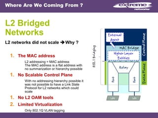
- 1. Where Are We Coming From ? L2 Bridged Networks L2 networks did not scale Why ? 1. The MAC address L2 addressing = MAC address The MAC address is a flat address with no summarization or hierarchy possible 1. No Scalable Control Plane With no addressing hierarchy possible it was not possible to have a Link State Protocol for L2 networks which could scale 1. No L2 OAM tools 2. Limited Virtualization Only 802.1Q VLAN tagging
- 2. SPB Provides Massive Simplification Extreme L2 SPB Networks Now a L2 SPB network scales 1.MACinMAC Encapsulation • IEEE 802.1 ah standard • Removes current Mac Address Scalability limitations • Separate Customer vs Backbone demarcation 1.Scalable Control Plane • IEEE 802.1 aq standard • uses the IS-IS routing Protocol which works at L2 1.L2 OAM tool • IEEE 801.ag standard • Connectivity & Fault Management (CFM) • Used for OAM 1.Designed for Virtualization • 802.1ah introduces a Service ID (I-SID) which can scale to 16 million services IP/SPB, SPBm/SPBm Protocol Infrastructure Ethernet Physical Infrastructur e Horizontally Independent Connectivity Services independent from Infrastructure Traditional Protocol Stack
- 3. 3 Todays Network using STP Layer 2 Some sort of loop prevention must be used, i.e. Spanning Tree, and enabled on all switches Spanning Tree will block ports based on cost to root bridge – all available paths cannot be used 50 MAC addresses 100 MAC addresses learned on all switches!! VLAN and port members must be provisioned on all switches
- 4. SPB No Spanning Tree in SPB core Customer VLAN & Services provisioned only at edge of network 50 MAC address 50 MAC address 100 MAC address VLAN provisioning only required at edge of network: simple as adding a VLAN, local ports, and assigning a Service Identifier. Customer MAC learning only at Edge of network, core never learns C-MAC (MAC learning and flooding only at edge, NOT in core). Customer MAC learning only at edge of network, core has zero end user MAC addresses SPB
- 5. © 2008 Extreme Networks, Inc. All rights reserved. ExtremeXOS Operation and Configuration, Version 12.1. Part number DOC-00919. Layer 2 Forwarding Technology ExtremeXOS™ Operation and Configuration, Version 12.1
- 6. Slide 6 Student Objectives Upon completion of this module, you will be able to: Describe transparent bridging. Describe the flooding and learning port states. Describe the forwarding and filtering port state. Describe the forwarding database. Identify the various FDB entry types. Manage forwarding database entries. Configure egress flooding. Configure and verify the limit-learning feature. Configure and verify the lock-learning feature. Configure the Extreme link status monitor.
- 7. ISO Seven Layer Reference Model Slide 7 L7 - APPLICATION L6 - PRESENTATION L5 - SESSION L4 - TRANSPORT L2 - DATA LINK L1 - PHYSICAL L3 - NETWORK Layer Description 7 Application level access to the network, file transfer, remote terminals 6 Translation of data structures between differing architectures 5 Provides for dialogue control between processes 4 Provides for end to end connection between machines 3 Where routing takes place 2 Defines protocols for exchanging data frames 1 Defines the standards for physical connections (the wire)
- 8. Slide 8 Collision Domain All hosts accessing the same physical media Host packets capable of colliding with each other Shared Medium – A common Ethernet cable
- 9. Slide 9 Carrier Sense Multiple Access with Collision Detection (CSMA/CD) Carrier Sense • Hosts sense if there is any current transmission in progress. • If there is a transmission in progress, hosts wait until it is finished. Multiple Access • Multiple hosts can participate in the same domain / share the same media. Collision Detection • Two or more hosts can still transmit at exactly the same instant, believing the media to be free. • If a collision occurs: The host sends a jamming signal to prevent any further transmission. It waits a random amount of time before trying to retransmit. • Allowed to retry up to 16 times.
- 10. Slide 10 Transparent Bridges Used for LAN Segmentation Bridges widely used to segment Ethernet collision domains Switches perform the bridge segmentation function in hardware Before… IPX UNIXIPX UNIX Excessive Delays After… IPX IPX UNIXUNIX Acceptable Delays Low Utilization Bridge
- 11. Slide 11 802.1d Transparent Bridges Used in Ethernet Networks A talks to B – Packet remains in 1st collision domain A talks to C – Bridge forwards packet to 2nd collision domain A switch performs the bridging function in hardware MAC Address based lookup table Collision Domain 2Collision Domain 1 C DIPX A BUNIX Bridge
- 12. Slide 12 Ethernet Frames A bridge learns host locations from Source MAC address. It makes forwarding decisions based on Destination MAC address. Ethernet Frame 6 Bytes 6 Bytes 2 Bytes 46 to 1500 Bytes 4 Bytes Destination MAC Source MAC Type / Length Data (Payload / Padding) CRC 64 Bytes Minimum. 1518 Bytes Maximum.
- 13. Slide 13 Bridge Functions The bridge can be performing one of four functions: • Flooding, Learning, Forwarding, Filtering
- 14. Slide 14 0B Flooding In a newly configured network, host “0B” initiates communication with host “1E”. Because the destination is unknown, the packet is flooded to all of the interfaces and host “0B” is learned on the inbound port. Payload1E 0B T/L CRC 0-300s100:01:30:00:00:0B TimerPort NumberMAC Address Forwarding Table 0A 0C 0D 0E 0F 1A 1B 1C 1D 1E 1F 1 3 52 4 6Pad- ding
- 15. Slide 15 Forwarding Host “1E” replies to host “0B”, and the packet is forwarded onto the destination port learned for “0B”. At the same time, the MAC address for “1E” is learned and added to the bridge table. Payload0B 1E T/L CRC 0-300s600:01:30:00:00:1E 0-300s100:01:30:00:00:0B TimerPort NumberMAC Address Forwarding Table 0A 0B 0C 0D 0E 0F 1A 1B 1C 1D 1E 1F 1 3 52 4 6Pad- ding
- 16. Slide 16 Filtering When the destination MAC address matches the inbound port, the switch drops the packet at the port. This reduces traffic on the other ports within the broadcast domain (VLAN) and optimizes performance. Payload0B 0A T/L CRC MAC Address Port Number Timer 00:01:30:00:00:0A 1 0-300s 00:01:30:00:00:0B 1 0-300s Forwarding Table 0A 0B 0C 0D 0E 0F 1A 1B 1C 1D 1E 1F 1 3 52 4 6Pad- ding
- 17. Slide 17 Forwarding Database Maintains a record of the location of each of the host MAC addresses. Enables the switch to make forwarding decisions. Entries are added dynamically by associating the source MAC field of the Ethernet frame with the port number. Has statically added entries. The administrator manually enters MAC and port number fields. Also known as the bridge table or FDB.
- 18. Slide 18 Forwarding Database Illustrated L2 address entries consists of: • MAC address, Port / Port ID, VLAN ID FDB
- 19. © 2008 Extreme Networks, Inc. All rights reserved. ExtremeXOS Operation and Configuration, Version 12.1. Part number DOC-00919. Layer 2 Forwarding Implementation ExtremeXOS™ Operation and Configuration, Version 12.1
- 20. FDB Entry Types Dynamic entries • Initially, all entries in the database are dynamic Static entries • Non-aging entries Entries with an aging timer set to zero • Permanent entries Entered through the CLI and saved as permanent Retained in the database after reset/power off • Black hole entries Created statically by the administrator Created automatically by security features such as lock-learning Configures FDB with specified source and/or destination MAC address to be discarded Slide 20
- 21. © 2008 Extreme Networks, Inc. All rights reserved. ExtremeXOS Operation and Configuration, Version 12.1. Part number DOC-00919. Managing FDB Entries Displaying, Adding, and Removing Database Entries
- 22. Displaying the FDB Table To display the contents of the layer 2 Forwarding Database, use the show fdb command: show fdb Slide 22 Results show MAC, VLAN, Age, Flags, and Port of each entry.
- 23. Adding Entries to the FDB To add a static entry to the FDB, use the create fdbentry command: create fdbentry <mac_addr> vlan <vlan_name> [ports <port_list> | blackhole] • Allows you to add a standard or blackhole entry to the FDB Examples commands • Add a permanent static entry to the FDB: create fdbentry 00:E0:2B:12:34:56 vlan finance port 3:4 • Add a black hole entry to the FDB: create fdbentry 00:E0:2B:12:34:56 vlan finance blackhole • Verify the results of the above commands: show fdb Slide 23
- 24. Removing Entries from the FDB To remove static entries from the FDB, use the delete fdbentry command: delete fdbentry [all | <mac_address> [vlan <vlan name>] To remove dynamic or black hole entries from the FDB, use the clear fdb command: clear fdb {<mac_address> | blackhole | ports <portlist> | vlan <vlan name>} Examples: • Remove a permanent entry from the FDB: delete fdbentry 00:E0:2B:12:34:56 vlan default • Remove a dynamic entry from the FDB: clear fdb 00:E0:2B:12:34:56 • To verify the results of the delete fdbentry or clear fdb command: show fdb Slide 24
- 25. © 2008 Extreme Networks, Inc. All rights reserved. ExtremeXOS Operation and Configuration, Version 12.1. Part number DOC-00919. Managing FDB Behavior Configuring MAC Address Learning and FDB Aging Time
- 26. Configuring MAC Address Learning To control if a switch learns the source addresses of incoming packets, use the disable / enable learning command. Determines if the source MAC address of incoming packets will be added to FDB. • Defines if incoming packets with unknown source MAC addresses are dropped or forwarded to the appropriate egress ports. MAC address learning is enabled by default and is configured on a per-port basis. Examples • To only forward packets with static FDB entries on port 5: disable learning drop-packets port 5 • To forward all packets received on this port: disable learning forward-packets port 5 • To view the MAC address learning configuration on port 5. The lowercase m flag indicates that MAC address learning is enabled. show ports 5 information Slide 26
- 27. Configuring the FDB Aging Time To configure how long the FDB maintains a dynamic entry in the FDB, use the configure fdb agingtime command: configure fdb agingtime <seconds> • Default: 300 seconds (5 minutes) • Range: 15 - 1,000,000 seconds • A value of 0 indicates that entries should never be aged out • The timer is restarted when a packet with a matching source MAC address is received on the same port. Examples • To change the FDB agetime to an hour: configure fdb agingtime 3600 • To ensure no entries in the FDB age out: configure fdb agingtime 0 • To verify the agingtime value: show fdb Slide 27
- 28. © 2008 Extreme Networks, Inc. All rights reserved. ExtremeXOS Operation and Configuration, Version 12.1. Part number DOC-00919. Managing Layer 2 Security Features Configuring Egress Flood Control
- 29. Describing Layer 2 Security Features ExtremeXOS has three features that enhance Layer 2 security • Egress Flood Control Determines whether broadcast, multicast, or unknown unicast packets are flooded. • Limit-Learning Limits the number of devices that can be learned. • Lock-Learning Freezes the FDB entries on a port / VLAN basis. Once enabled, this feature does not allow new MAC address entries to be added dynamically. Configured by port or port / VLAN • Egress Flooding Control - Port • limit-learning - Port / VLAN • lock-learning - Port / VLAN Slide 29
- 30. Egress Flood Control ExtremeXOS enables you to manage the types of packets that get flooded out to the network. Egress flooding takes action on a packet based on the packet destination MAC address. By default, egress flooding is enabled. You can enhance security and privacy as well as improve network performance by disabling Layer 2 egress flooding on some packets. Slide 30 Disabling multicasting egress flooding does not affect those packets within an IGMP membership group Client 1 Client 2 Access Link Port 1 Access Link Port 2 Uplink Port 3 EXOS Switch / Access VLAN ISP FW / Security Proxy With all_cast flooding disabled, clients will only see known unicast packets.
- 31. Configuring Egress Flood Control To control egress flooding, use the enable / disable flooding command with the port option. Examples • To disable flooding of unknown unicast packets on port 1: disable flooding unicast port 1 • To enable flooding of broadcast packets on all ports: enable flooding broadcast port all • To verify egress flooding configuration on port 1: show port 1 info detail Slide 31 The broadcast, multicast, and unicast parameters are available only on the BlackDiamond 8800 series switches, SummitStack, and the Summit family of switches.
- 32. Configuring Limit-Learning This security feature allows you to limit the number of MAC addresses that can be dynamically-learned by using the configure ports command with the limit-learning option: • Allows the first N number of hosts. • All hosts thereafter are denied access. The traffic is blocked as a black hole entry. Both ingress and egress. • Based on source MAC address Examples • To limit the number of MAC addresses learned on port 1 for VLAN accounting to three entries: configure ports 1 vlan accounting learning-limit 3 • To remove the learning limit from port 1 for VLAN accounting: configure ports 1 vlan accounting unlimited-learnings Slide 32 FDB MAC 1 MAC 2 MAC 3 Port 1 limit
- 33. Configuring Lock-Learning To lock entries in the FDB, use the configure ports command with the lock-learning option: • The entries in the FDB are frozen into a locked static state. • New dynamic FDB entries are inserted as black hole entries. • You can either limit dynamic MAC FDB entries, or lock down the current MAC FDB entries per port/VLAN, but not both. Examples: • To lock the FDB entries associated with port 4 and the accounting VLAN: configure ports 4 vlan accounting lock-learning • To unlock the FDB entries associated with port 4 and the accounting VLAN: configure ports 4 vlan accounting unlock-learning Slide 33 Unknown MAC Known MAC
- 34. Verifying Limit-Learning and Lock-Learning show fdb Slide 34
- 35. Verifying Limit-Learning and Lock-Learning (continued…) show vlan default security Slide 35
- 36. Extreme Link Status Monitoring (ELSM) Extreme Networks proprietary protocol that monitors network health by detecting CPU and remote link failures Detects switch CPU failures that could result in a ESRP or EAPS loop in the network Operates on a point-to-point basis and is configured on both sides of the peer connections When ELSM is down, data packets are neither forwarded nor transmitted out of that port Slide 36 Hello messages Hello messages
- 37. Verifying Extreme Link Status Monitoring show elsm ports 3 Slide 37 ELSM state can be UP, Down, Down-wait, or Down-stuck
- 38. Summary You should now be able to: Define transparent bridging. Define the flooding and learning port states. Define the forwarding and filtering port state. Define the forwarding database. Identify the various FDB entry types. Manage forwarding database entries. Configure egress flooding. Configure and verify the limit-learning feature. Configure and verify the lock-learning feature. Configure the Extreme link status monitor. Slide 38
- 39. Slide 39 Lab Turn to the Layer 2 Forwarding Lab in the ExtremeXOS™ Operations and Configuration - Lab Guide Rev. 12.1 and complete the hands-on portion of this module.
- 40. © 2008 Extreme Networks, Inc. All rights reserved. ExtremeXOS Operation and Configuration, Version 12.1. Part number DOC-00919. Review Questions
- 41. © 2008 Extreme Networks, Inc. All rights reserved. ExtremeXOS Operation and Configuration, Version 12.1. Part number DOC-00919. This presentation contains forward-looking statements that involve risks and uncertainties, including statements regarding our expectations as to products, trends and our performance. There can be no assurances that any forward-looking statements will be achieved, and actual results could differ materially from forecasts and estimates. For factors that may affect our business and financial results please refer to our filings with the Securities and Exchange Commission, including, without limitation, under the captions: “Management’s Discussion and Analysis of Financial Condition and Results of Operations,” and “Risk Factors,” which is on file with the Securities and Exchange Commission (http://www.sec.gov). We undertake no obligation to update the forward-looking information in this release.
- 42. © 2008 Extreme Networks, Inc. All rights reserved. ExtremeXOS Operation and Configuration, Version 12.1. Part number DOC-00919. The End © 2008 Extreme Networks, Inc. All rights reserved. ExtremeXOS Operation and Configuration, Version 12.1. Part number DOC-00919.
Hinweis der Redaktion
- Imagine using our switching as a policy enforcement engine to manage your network. Extreme offers a Carrier-class solution for the delivery of business and residential Ethernet services. Extreme Networks Metro Ethernet offerings enable service provider customers to offer a variety of business and residential Ethernet services using a resilient, high performance and service rich platform. Extreme Switch Hardware based design so the ISD will experience no performance penalty for running advanced features such as Multicast, ACLs, and QoS. Extreme can deliver the ISD Special Service Differentiation. The need for business continuity has placed a greater demand on today’s data networks – redundancy and reliability are imperative and the network must be able to support them. The network infrastructure must be able to achieve a high availability environment and continuous access to resources. For this reason, the networking industry has relied on the Spanning Tree Protocol (STP) in large Layer 2 networks to provide a certain level of redundancy. However, STP has proven inadequate to provide the level of resiliency required for real-time and mission critical applications. It is important to note that the entire industry has recognized that a new technology is needed to replace STP and many vendors are in the process of developing pre-standard technologies to meet that requirement. The control plane is the part of the router architecture that is concerned with drawing the network topology, or the information in a (possibly augmented) routing table. In most cases, the routing table contains a list of destination addresses and the outgoing interface(s) associated with them. Control plane logic also can define certain packets to be discarded, as well as preferential treatment of certain packets for which a high quality of service is defined by such mechanisms as differentiated services.
- A major function of the control plane is deciding which routes go into the main routing table. &quot;Main&quot; refers to the table that holds the unicast routes that are active. Multicast routing may require an additional routing table for multicast routes. Several routing protocols e.g. IS-IS, OSPF and BGP maintain internal databases of candidate routes which are promoted when a route fails or when a routing policy is changed. Service providers began building metro Ethernet networks in the late 1990s to provide a cost-effective alternative to TDM-based leased lines and legacy switching technologies such as ATM and frame relay. Initially, they paid little attention to the issue of scaling the metro, because the networks were new and had few subscribers and small amounts of traffic. Since then, the popularity of metro Ethernet has grown tremendously, and leading analysts predict that 20% annual growth will continue in the coming years. To prepare their networks for the onset of many new subscribers and ever-rising volumes of traffic, service providers must be ready to scale today. Carrier Ethernet networks are typically composed of three tier systems—with switching equipment located at the customer edge, provider edge and provider aggregation. Not all networks will use all three tiers. For example, an IPTV network may be deployed using only a provider aggregation switch at a provider point of presence, skipping the provider edge. The provider edge is the Central Office (CO) used for service delivery. There is some cross over between provider edge and provider aggregation. Depending on the size of the network and the physical geography of the deployment, a service provider may do aggregation at either the provider edge or at a larger provider aggregation site. The customer edge includes building basements and wiring closets where switches are deployed for business services as well as multi-tenant apartment buildings for residential services.
- The forwarding plane, sometimes called the data plane or user plane, defines the part of the router architecture that decides what to do with packets arriving on an inbound interface. Most commonly, it refers to a table in which the router looks up the destination address of the incoming packet and retrieves the information necessary to determine the path from the receiving element, through the internal forwarding fabric of the router, and to the proper outgoing interface(s). The IP Multimedia Subsystem architecture uses the term transport plane to describe a function roughly equivalent to the routing control plane. In certain cases, the table may specify that a packet is to be discarded. In such cases, the router may return an ICMP &quot;destination unreachable&quot; or other appropriate code. Some security policies, however, dictate that the router should drop the packet silently, in order that a potential attacker does not become aware that a target is being protected. IEEE 802.1Q Data Plane Actions for XYZ Account… Providers are confronted with two distinct facets to metro Ethernet scalability. The first is subscriber scalability: the ability to seamlessly add large numbers of customers to the network without affecting operation. In general, the passage from the input interface directly to an output interface, through the fabric with minimum modification at the output interface, is called the fast path of the switch. If the packet needs significant processing, such as segmentation or encryption, it may go onto a slower path, which is sometimes called the services plane of the router. Service planes can make forwarding or processing decisions based on higher-layer information, such as a Web URL contained in the packet payload. The outgoing interface will encapsulate the packet in the appropriate data link protocol. Depending on the router software and its configuration, functions, usually implemented at the outgoing interface, may set various packet fields, such as the DSCP field used by differentiated services.
- A Data Center with SPB and SDN Control for XYZ Account… A further consequence of SPBM&apos;s transparency in both data plane and control plane is that it provides a perfect, &quot;no compromise&quot; delivery of the complete MEF 6.1 service set. This includes not only E-LINE and E-LAN constructs, by also E-TREE (hub-and-spoke) connectivity. SPBV supports shortest path trees but SPBV also builds a spanning tree which is computed from the link state database and uses the Base VID. This means that SPBV can use this traditional spanning tree for computation of the Common and Internal Spanning Tree (CIST). The CIST is the default tree used to interwork with other legacy bridges. It also serves as a fall back spanning tree if there are configuration problems with SPBV. SPBV has been designed to manage a moderate number of bridges. SPBM offers both the ideal multicast replication model, where packets are replicated only at fork points in the shortest path tree that connects members, and the less state intensive head end replication model where serial unicast packets are sent to all other members along the same shortest path first tree. These two models are selected by specifying properties of the service at the edge which affect the transit node decisions on multicast state installation. This allows for a trade-off to be made between optimum transit replication points (with their larger state costs) vs. reduced core state (but much more traffic) of the head end replication model. These selections can be different for different members of the same Individual Service ID (I-SID) allowing different trade-offs to be made for different members.
- ExtremeXOS™ Operation and Configuration, Version 12.1 - Layer 2 Forwarding
- ExtremeXOS™ Operation and Configuration, Version 12.1 - Layer 2 Forwarding Implementation
- Basically, we have dynamic entries and static entries. Remember, dynamic entries are any entry that was learned automatically or dynamically by the switch based on the source MAC address and ingress port. We have static entries, and in static entries, we have non-aging entries, permanent entries, and black hole entries. Non-aging entries are simply entries with an aging time set to zero. Permanent entries were manually entered on the CLI by the Administrator, and were saved as permanent. Permanent entries are retained in the database even through a power cycle or switch reboot. Lastly, we have black hole entries. Again, black hole entries are created statically by the Administrator. The Administrator may have created an entry in there for security or to block undesired traffic on the network. For example, let’s say there was a denial of service attack being launched by a particular host, and the Administrator was able to determine that device’s MAC address. We can then go in and create a black hole entry that says “Any traffic coming into the switch sourced from this particular MAC address, simply discard that frame.” Additionally, black hole entries can be created automatically by some of Extreme Network’s basis security features such as lock-learning and limit-learning.
- Here you see an example of the output of show fdb There is an important things to note here: On the left-hand side of the slide, you can see the MAC address of individual devices. Next, we see the VLAN column and you can look and see all of the devices that are associated with the default VLAN. You see the Age column. This is the amount of time that has lapsed since the last time this particular device has been heard on the wire. And then, the physical port number. Ports, you see here, ports 2, 3, and 7 are in use.
- The next command you can use to verify MAC security is: show vlan &lt;space&gt; vlan name &lt;space&gt; security In this case, we’re looking at VLAN Default and you can see on port 7, we’ve locked learning on Port 7 and you can see that there was one dynamic entry in the FDB at the time that we locked learning on Port 7.
- Extreme Link Status Monitoring (ELSM) is Extreme Networks’ proprietary protocol that monitors network health by detecting CPU and remote link failures. ELSM does this by sending hello messages between two ELSM peers. Should one of the remote switches, CPUs, fail, we detect this by the fact that we’re no longer receiving ELSM messages from that peer, in which case we would actually block the link This can be helpful in a case of, say, ESRP, in preventing dual-ESRP masters. ELSM operates on a point-to-point basis, and must be configured on both sides of the peer connection. If ELSM is only configured on one end of the link and is not configured on the other end of the link, that port on the switch that ELSM is enabled on, will be set in to a blocking state, and will only be set in to a forwarding state once it actually starts communicating with the ELSM peers.
- Use the command show ELSM ports and the port number to determine the ELSM state.
- You should be now able to: Describe ExtremeXOS Layer 2 features Describe basic Transparent Bridging Define Flooding and Learning port states Define the Forwarding and Filtering port states Define the basics of the FDB Create FDB entries Configure and verify the limit-learning feature Configure and verify the lock-learning feature And configure and verify the settings of ELSM