Separator Control with liquid level control and dump valve
•
1 gefällt mir•2,493 views

The SOR 1450 valve is a close-coupled control valve and designed to meet the high pressure and erosive applications common to the oil and gas industry. These valves are ideally suited for process media control applications including: controlling liquid level on 2 or 3 phase gas separators, gas dehydrators, compressors, scrubbers, heater treaters and well test systems, as well as other oil field equipment. The ease of maintenance, rugged steel construction, flexibility to meet a wide variety of applications, and safety features make these control valves the preferred choice of production operators worldwide.

Empfohlen
Empfohlen
Weitere ähnliche Inhalte
Andere mochten auch
Andere mochten auch (10)
Mehr von Instrument Specialties, Inc.
Mehr von Instrument Specialties, Inc. (20)
Kürzlich hochgeladen
Kürzlich hochgeladen (20)
Separator Control with liquid level control and dump valve
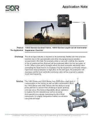
- 1. Application Note Product The Application Solution 14685 West 105th Street, Lenexa, Kansas 66215 | 913-888-2630 | Fax 913-888-0767 | SORInc.com Challenge 1400 Series Control Valve, 1600 Series Liquid Level Controller Separator Control The 1400 Series and 1600 Series from SOR offer a high level of customization in the factory as well as field customization. Both the 1400 Series and 1600 Series offer the ability to swap pilots and trim to convert from throttling to quick opening and vice versa. This field configurability allows operators to replace the trim and pilots as well as ensuring that operators are always maximizing the life of their instruments. In a highly competitive market, we all know every little bit helps! The oil and gas industry is required to be particularly flexible with their process controls due to the unpredictable and often changing process variables encountered in the field. For example, when a new well is drilled, the majority of the oil produced from that well will be produced within the first two years of its life. When a new well is brought online, the level controller and dump valve controlling the liquid level in its separator may be required to continually remove liquid level since production is high. But, as the well ages, the production will decrease and the level controller and dump valve will be required to operate much less frequently.
- 2. SORInc.com | 913-888-2630 | Registered Quality System to ISO 9001 1/14Form 1639 (10.16) ©SOR Inc. 1400 Series Control Valves • Fail-open or fail-close configurations available • Easy to maintain with no special tools required • Field repairable with multiple kits available • Optional Tungsten carbide hardened trim for erosive applications • NACE and high-temperature configurations available • NPT, flanged, socket weld and butt weld end connections • Designed to ANSI class IV shutoff classification FeaturesandBenefits The 1400 series control valves are designed to be used in rugged, demanding applications like those found in the oil and gas industry. These valves are time tested to deliver increased reliability in the most demanding applications around the world. Each model is designed to provide superior performance and solve industry specific challenges. Applications The 1400 series control valves are designed specifically to be used in conjunction with oil production equipment. The 1450 is a close coupled control valve designed for high pressure separators and scrubbers, and other processing equipment. The 1451 is a compact, uniquely designed product, to allow the plug and the seat to beconstantly submerged in the process media, giving the valve its “freezeless” characteristic. The 1400 series control valves can be used as direct replacements for competitive units already in service or packaged with other SOR products for new construction of oil and gas production equipment. Model 1450 (page 3) Model 1451 (page 11) SEE MORE AT SORInc.com Request Quote
- 3. Registered Quality System to ISO 9001 | 913-888-2630 | SORInc.com2/14 Form 1639 (10.16) ©SOR Inc. Principles of Operation 1400 Series Control Valves The 1400 series control valves are modeled after an industry standard design of control valves specifically designed to be used in oil and gas production equipment. The 1400 series control valves are intended to be used in tandem with a level controller that provides a pneumatic signal to operate the valve. All 1400 series control valves require a pneumatic input to operate. The pneumatic signal operates a force balance system consisting of: an adjusting spring, a diaphragm, a stem, a plug and seat. The force of the adjusting spring opposes the force of the pneumatic signal on the diaphragm. As pressure is either increased or reduced on the diaphragm, the plug is raised and lowered from the seat – this allows process fluid to flow through the valve. The plug and the seat are very important components to the operation of the valve. The surface finish of the plug and seat determines if the valve will seal effectively. The shape of the plug determines the flowing characteristics of the valves. On/off trim is designed to only allow the valve to be completely open or completely shut. Throttling trim is designed to provide a percentage of full flow capacity at designated pneumatic inputs. The 1450 series control valves are offered with either globe or tee body styles. The globe style body allows the process fluid to flow either direction – over the trim or under the trim. The tee body has three ports allowing a plug to be placed in one port to change the direction of flow from globe style to angle style body. Adjusting Spring Diaphragm Breather Plug Packing Set Plug Cage/Seat Ring FAIL-OPEN Travel Indicator Spring Cover Upper Spring Retainer Diaphragm Plate Set Screw at Base of Cover Travel Indicator Adjusting Spring Diaphragm Packing Set Plug Cage/Seat Ring FAIL-CLOSED Adjusting Screw Upper Spring Retainer Diaphragm Plate Spring Housing Adjusting Nut
- 4. SORInc.com | 913-888-2630 | Registered Quality System to ISO 9001 3/14Form 1639 (10.16) ©SOR Inc. Design and specifications are subject to change without notice. For latest revision, see SORInc.com. Available configurations Close-coupled (Model 1450) Fail-open or fail-close Flow characteristic Modified percent (throttling) Quick opening (on/off) Body styles Globe (1” & 2”) & tee (1” only) End connections NPT(F), flanged, socket weld & butt weld Pressure ratings 3750 psi at 100˚F Assembled valve temperature range -40 to 200˚F (-40 to 93˚C) Product Specifications Available trim sizes 1/4”, 3/8”, 1/2”, 3/4” & 1” Shutoff classification ANSI class IV (Stainless steel or Tungsten carbide trim) Flow direction Either direction, to suit the application Flow up (under the seat) recommended for throttling applications Air pressure to actuator 3-15 spring 0 to 20 psi control signal recommended 6-30 spring 0 to 35 psi control signal recommended 1450 Control Valve 1400 Series Control Valves Model 1450 The SOR 1450 valve is a close-coupled control (dump) valve and is designed to meet the high pressure and erosive applications common to the oil and gas industry. These valves are ideally suited for process media control applications including: separators, scrubbers, wellheads and other oilfield equipment. The ease of maintenance, rugged steel construction, flexibility to meet a wide variety of applications, and safety features make these control valves the preferred choice of production operators worldwide. Features • Ease of maintenance - No special tools - Field repairable - Field replaceable trim • Bonnet safety pressure relief • NACE and high-temperature configurations available • Optional Tungsten carbide hardened trim for erosive applications • Reverse and direct acting options • Bi-directional flow
- 5. Registered Quality System to ISO 9001 | 913-888-2630 | SORInc.com4/14 Form 1639 (10.16) ©SOR Inc. 1450 Control Valve 1400 Series Control Valves 3Pressure Rating NPT(F) (3750 PSI) ANSI 150# ANSI 300# ANSI 600# ANSI 900# A C D E F No. 35 Act. w/3-15 Spring No. 35 Act. w/6-30 Spring No. 70 Act. w/3-15 Spring No. 70 Act. w/6-30 Spring 5Actuator Selection 33 36 73 76 2 1* 2 6Actuator Type R D Reverse (Fail Close) Direct (Fail Open) 7 Trim Size 2 3 4 6 8 1/4” 3/8” 1/2” 3/4” 1” 8 Body Style T G Tee (only available on 1” Body Size) Globe 10 Seal Material B V Buna-N Viton® Trim Characteristic S T Quick Opening Throttle 9 End Connection T R J NPT(F) Raised Face Flange Ring Type Joint Flange 4 1018/A105 CS 1018/A105 CS (NACE) Body Material A N 12 11 S T 17-4PH Stainless Steel Tungsten Carbide Trim Material Body Size Model 1 1450 Close- coupled valve 1450 - 1” 2” 1450 - 2 A A 36- D 4 G T - B S S Example Model No. How to Order Below is the SOR quick select model number tree that provides you with all the options to configure and order a product for your application. • You must select a designator for each component • Reference tables, charts and additional information are provided throughout the catalog to help you make your selections, see pages noted in the tree. * 1” body size only available with NPT(F) pressure rating.
- 6. SORInc.com | 913-888-2630 | Registered Quality System to ISO 9001 5/14Form 1639 (10.16) ©SOR Inc. 1450 Options 1400 Series Control Valves Valve Component Options Body ASTM A216 Gr. WCC Bonnet 316 Stainless Steel Hammer Nut 4140 Steel Stem 316 Stainless Steel Packing TFE V Ring Packing Spring 302 Stainless Steel Packing Washer CSTL Packing Retainer 17-4 PH O-Ring Wetted Nitrile Viton Diaphragm Neoprene/Nylon O-Ring Non Wetted Nitrile Viton Actuator Spring Steel Adjust. Screw CSTL/PLtd. Diaphragm Housing CSTL Diaphragm Plate CSTL Travel Indicator Stainless Steel Actuator Pressure Connection Size 1/4” - 18 NPT Thread Body Size Trim Size Valve Opening - Percent of Total Travel Quick Opening in. mm in. mm 10% 20% 30% 40% 50% 60% 70% 80% 90% 100% 100% 1.00 25 0.25 6.4 .28 .51 .66 .77 .88 .99 1.1 1.2 1.3 1.4 1.7 0.38 9.5 .31 .62 .94 1.3 1.6 2.1 2.5 2.9 3.4 3.7 3.8 0.50 12.7 .56 1.1 1.7 2.3 2.9 3.6 4.3 5.0 5.4 5.6 5.6 0.75 19.1 .75 1.6 2.4 3.4 4.6 6.1 7.9 9.7 11 11 12 1.0 25.4 .98 2.0 3.4 6.1 8.9 12 14 14 15 15 15 2.00 50 0.25 6.4 .28 .51 .66 .77 .88 .99 1.1 1.2 1.3 1.4 1.7 0.38 9.5 .31 .62 .94 1.3 1.6 2.1 2.5 2.9 3.4 3.7 3.8 0.50 12.7 .59 1.2 1.8 2.3 3.0 3.7 4.6 5.5 6.0 6.1 6.1 0.75 19.1 .88 1.8 2.8 3.8 5.1 6.6 8.5 11 12 13 13 1.0 25.4 1.0 2.0 3.6 6.5 9.4 12 14 15 17 17 18 Body Size Pressure Rating NPT Body Style in. mm psi bar 1.00 25 3750 259 X Globe, “T” 2.00 50 3750 259 X Globe Materials of Construction Body End Connections and Pressure Ratings Estimated Flow Coefficient (Cv) Globe Body
- 7. Registered Quality System to ISO 9001 | 913-888-2630 | SORInc.com6/14 Form 1639 (10.16) ©SOR Inc. 1450 Options 1400 Series Control Valves Trim Size Flow Direction Signal to No. 35 Actuator Signal to No. 70 Actuator 3-15 Spring 6-30 Spring 3-15 Spring 6-30 Spring in. mm 3-15 psi 0-20 psi 6-30 psi 0-35 psi 3-15 psi 0-20 psi 6-30 psi 0-35 psi 0.25 6.4 Up 3750 3860 3750 3750 3750 3750 3750 3750 0.38 9.5 2050 3200 3400 3750 3750 3750 3750 3750 0.50 12.7 1100 1600 1800 2300 1650 3200 3750 3750 0.75 19.1 300 500 700 950 500 950 2000 2800 1.0 25.4 100 200 300 500 200 400 950 1450 0.25 6.4 Down 3750 3800 3750 3750 3750 3750 3750 3750 0.38 9.5 3750 3800 3750 3750 3750 3750 3750 3750 0.50 12.7 3350 3800 3750 3750 3750 3750 3750 3750 0.75 19.1 1550 2300 2500 3200 2000 2800 3750 3750 1.0 25.4 750 1100 1200 1700 950 1450 2500 2950 Trim Size Flow Direction Signal to No. 35 Actuator1 Signal to No. 70 Actuator1 Flow Direction Signal to No. 35 Actuator1 Signal to No. 70 Actuator1 in. mm 3-15 Spring 6-30 Spring 3-15 Spring 6-30 Spring 3-15 Spring 6-30 Spring 3-15 Spring 6-30 Spring 0.25 6.4 Up 3750 3750 3750 3750 Down 3750 3750 3750 3750 0.38 9.5 2700 3750 3750 3750 3750 3750 3750 3750 0.50 12.7 1350 2850 2550 3750 3800 3750 3750 3750 0.75 19.1 400 1050 700 2000 1750 1950 3750 3750 1.0 25.4 150 500 200 950 850 950 1850 2800 1 Actual signal pressure to actuator includes an additional 5 psi (0.3 bar) of supply pressure to the controller. Actuator Maximum Allowable Shutoff Pressure Drops, Reverse Acting (Fail Close) Actuator Maximum Allowable Shutoff Pressure Drops, Direct Acting (Fail Open) Diaphragm Effective Area & Housing Max. Pressure Actuator Size Diaphragm Effective Area Housing Maximum Pressure No. 35 35 in2 50 psi No. 70 70 in2 35 psi
- 8. SORInc.com | 913-888-2630 | Registered Quality System to ISO 9001 7/14Form 1639 (10.16) ©SOR Inc. 1450 Options 1400 Series Control Valves Only genuine SOR replacement parts should be used to make repairs. Please contact your local representative for ordering information. Trim Replacement Kits Quick Opening 1/4” 3/8” 1/2” 3/4” 1” 17-4PH SST (BUNA-N O-Ring) 5678400P 5678401P 5678402P 5678403P 5678404P 17-4PH SST (VITON O-Ring) 5678405P 5678406P 5678407P 5678408P 5678409P Tungsten (BUNA-N O-Ring) 5678410P 5678411P 5678412P 5678413P 5678414P Tungsten (VITON O-Ring) 5678415P 5678416P 5678417P 5678418P 5678419P Throttling 17-4PH SST (BUNA-N O-Ring) 5678420P 5678421P 5678422P 5678423P 5678424P 17-4PH SST (VITON O-Ring) 5678425P 5678426P 5678427P 5678428P 5678429P Tungsten (BUNA-N O-Ring) 5678430P 5678431P 5678432P 5678433P 5678434P Tungsten (VITON O-Ring) 5678435P 5678436P 5678437P 5678438P 5678439P Actuator Repair Kits 35 in2 Actuator Direct Acting BUNA-N O-Rings 5678488P Direct Acting VITON O-Rings 5678489P Reverse Acting BUNA-N O-Rings 5678486P Reverse Acting VITON O-Rings 5678487P 70 in2 Actuator Direct Acting BUNA-N O-Rings 5678492P Direct Acting VITON O-Rings 5678493P Reverse Acting BUNA-N O-Rings 5678490P Reverse Acting VITON O-Rings 5678491P Packing Kits Direct Acting BUNA-N Packing 5678495P Direct Acting VITON Packing 5678497P Reverse Acting BUNA-N Packing 5678494P Reverse Acting VITON Packing 5678496P Repair Kits
- 9. Registered Quality System to ISO 9001 | 913-888-2630 | SORInc.com8/14 Form 1639 (10.16) ©SOR Inc. 1450 Dimensions 1400 Series Control Valves ISO-9001 146 66.7 2-5/8 79.4 3-1/8 158.8 6-1/4 44.7 1-49/64 135.3 5-21/64 C 77.5 3-3/64 B A Model Name: 5678455.ASSEM/1.1 PRODUCT CERTIF ALL DIMENSIO UNLESS OTHE LINEA THIS DRAWIN NO USE WHATSO HEREON, NOR RE MADE WITHOUT T TITLE DIM DWG 1450 CO W/1"NPTF GLOBE B EO NUMBER: 5319 SCALE: 0.35 DO NOT SCALE PRINT MODEL # SALES ORDER # LINE ITEM # PURCHASE ORDER # ACTUATOR SELECTION DIM A 35/3-15 241.3 9-1/2 35/6-30 241.3 9-1/2 70/3-15 317.5 12-1/ 70/6-30 317.5 12-1/ 2X 1" NPTF 1/4" NPTF ISO-9001 14685 W 105TH ST LENEXA, KS 66215 USA 913-888-2630 SORINC.COM 4.7 49/64 35.3 21/64 C 7.5 -3/64 PRODUCT CERTIFICATION DRAWING ALL DIMENSIONS ARE 1/16 IN UNLESS OTHERWISE SPECIFIED LINEAR = MM IN DRAWN BY J REHM CHECKED BY M SMITH ENGINEER APPROVAL S BOAL DATE 10/22/15 THIS DRAWING IS THE EXCLUSIVE PROPERTY OF SOR. NO USE WHATSOEVER OF THE INFORMATION CONTAINED HEREON, NOR REPRODUCTION IN WHOLE OR PART MAY BE MADE WITHOUT THE EXPRESS WRITTEN PERMISSION OF SOR. TITLE DIM DWG 1450 CONTROL VALVE FAIL CLOSE W/1"NPTF GLOBE BODY EO NUMBER: 5319 SCALE: 0.35 DO NOT SCALE PRINT DRAWING NUMBER REV 5678455 1 SHEET 1 OF 1 DWG SIZE B SE ORDER # SALES PAGE ACTUATOR SELECTION DIM A DIM B DIM C 35/3-15 241.3 9-1/2 69.9 2-3/4 316.0 12-7/16 35/6-30 241.3 9-1/2 108.0 4-1/4 363.5 14-5/16 70/3-15 317.5 12-1/2 108.0 4-1/4 363.5 14-5/16 70/6-30 317.5 12-1/2 108.0 4-1/4 439.7 17-5/16 ISO-9001 14685 66.7 2-5/8 95.3 3-3/4 190.5 7-1/2 42.9 1-11/16 135.3 5-21/64 C 77.5 3-3/64 B A Model Name: 5678456.ASSEM/1.1 PRODUCT CERTIFIC ALL DIMENSIONS UNLESS OTHERW LINEAR THIS DRAWING IS NO USE WHATSOEV HEREON, NOR REPRO MADE WITHOUT THE TITLE DIM DWG 1450 CONT W/2"NPTF GLOBE BOD EO NUMBER: 5319 SCALE: 0.35 DO NOT SCALE PRINT MODEL # SALES ORDER # LINE ITEM # PURCHASE ORDER # ACTUATOR SELECTION DIM A 35/3-15 241.3 9-1/2 35/6-30 241.3 9-1/2 70/3-15 317.5 12-1/2 70/6-30 317.5 12-1/2 2X 2" NPTF 1/4" NPTF E ORDER # SALES PAGE ACTUATOR SELECTION DIM A DIM B DIM C 35/3-15 241.3 9-1/2 69.9 2-3/4 316.0 12-7/16 35/6-30 241.3 9-1/2 108.0 4-1/4 363.5 14-5/16 70/3-15 317.5 12-1/2 108.0 4-1/4 363.5 14-5/16 70/6-30 317.5 12-1/2 108.0 4-1/4 439.7 17-5/16 Drawing 5678455 Dimensions in this catalog are for reference only. They may be changed without notice. Contact the factory for certified drawings for a particular model number. Dimensions are expressed as millimeters over inches (Linear = mm/in.) Drawing 5678456 2 Inch Globe Fail-Closed 1 Inch Globe Fail-Closed
- 10. SORInc.com | 913-888-2630 | Registered Quality System to ISO 9001 9/14Form 1639 (10.16) ©SOR Inc. 1450 Dimensions 1400 Series Control Valves Drawing 5678453 1 Inch Tee Fail-Closed ISO-9001 14 79.4 3-1/8 158.8 6-1/4 135.3 5-21/64 C 66.7 2-5/8 A B 79.4 3-1/8 77.5 3-3/64 Model Name: 5678303.ASSEM/1.16 PRODUCT CERT ALL DIMENS UNLESS OTH LINE THIS DRAWI NO USE WHAT HEREON, NOR R MADE WITHOUT TITLE DIM DWG 1450 C W/1"NPTF TEE BO EO NUMBER: 53 SCALE: 0.35 DO NOT SCALE PRI MODEL # SALES ORDER # LINE ITEM # PURCHASE ORDER # ACTUATOR SELECTION DIM 35/3-15 24 9-1 35/6-30 24 9-1 70/3-15 31 12- 70/6-30 31 12- 3X 1" NPTF 1/4" NPTF 1"NPT PLUG ISO-9001 14685 W 105TH ST LENEXA, KS 66215 USA 913-888-2630 SORINC.COM 64 C 79.4 3-1/8 4 PRODUCT CERTIFICATION DRAWING ALL DIMENSIONS ARE 1/16 IN UNLESS OTHERWISE SPECIFIED LINEAR = MM IN DRAWN BY J REHM CHECKED BY M SMITH ENGINEER APPROVAL S BOAL DATE 10/16/15 THIS DRAWING IS THE EXCLUSIVE PROPERTY OF SOR. NO USE WHATSOEVER OF THE INFORMATION CONTAINED HEREON, NOR REPRODUCTION IN WHOLE OR PART MAY BE MADE WITHOUT THE EXPRESS WRITTEN PERMISSION OF SOR. TITLE DIM DWG 1450 CONTROL VALVE FAIL CLOSE W/1"NPTF TEE BODY EO NUMBER: 5319 SCALE: 0.35 DO NOT SCALE PRINT DRAWING NUMBER REV 5678453 1 SHEET 1 OF 1 DWG SIZE B ORDER # SALES PAGE ACTUATOR SELECTION DIM A DIM B DIM C 35/3-15 241.3 9-1/2 69.9 2-3/4 316.0 12-7/16 35/6-30 241.3 9-1/2 108.0 4-1/4 363.5 14-5/16 70/3-15 317.5 12-1/2 108.0 4-1/4 363.5 14-5/16 70/6-30 317.5 12-1/2 108.0 4-1/4 439.7 17-5/16 Dimensions in this catalog are for reference only. They may be changed without notice. Contact the factory for certified drawings for a particular model number. Dimensions are expressed as millimeters over inches (Linear = mm/in.)
- 11. Registered Quality System to ISO 9001 | 913-888-2630 | SORInc.com10/14 Form 1639 (10.16) ©SOR Inc. ISO-900 66.7 2-5/8 E D 42.9 1-11/16 135.3 5-21/64 C 77.5 3-3/64 B A F Model Name: 5678448.ASSEM/1.1 PRODU ALL D UNLE TH NO US HEREO MADE W TITLE DIM DWG W/2" FLG EO NUMB SCALE: 0. DO NO MODEL # SALES ORDER # LINE ITEM # PURCHASE ORDER # ACTUATO SELECTIO 35/3-15 35/6-30 70/3-15 70/6-30 FLANGE RF 150# RF 300# RF 600# RF 900#/1500 RTJ 150# RTJ 300# RTJ 600# RTJ 900#/1500 2X 2" FLANGE 1/4" NPTF Drawing 5678448 2 inch FLG globe Fail-Closed 1450 Dimensions 1400 Series Control Valves Dimensions in this catalog are for reference only. They may be changed without notice. Contact the factory for certified drawings for a particular model number. Dimensions are expressed as millimeters over inches (Linear = mm/in.) ISO-9001 14685 W 105TH ST LENEXA, KS 66215 USA 913-888-2630 SORINC.COM C PRODUCT CERTIFICATION DRAWING ALL DIMENSIONS ARE 1/16 IN UNLESS OTHERWISE SPECIFIED LINEAR = MM IN DRAWN BY J REHM CHECKED BY M SMITH ENGINEER APPROVAL S BOAL DATE 1/28/16 THIS DRAWING IS THE EXCLUSIVE PROPERTY OF SOR. NO USE WHATSOEVER OF THE INFORMATION CONTAINED HEREON, NOR REPRODUCTION IN WHOLE OR PART MAY BE MADE WITHOUT THE EXPRESS WRITTEN PERMISSION OF SOR. TITLE DIM DWG 1450 CONTROL VALVE FAIL CLOSE W/2" FLG GLOBE BODY ASSY EO NUMBER: 5319A SCALE: 0.35 DO NOT SCALE PRINT DRAWING NUMBER REV 5678448 1 SHEET 1 OF 1 DWG SIZE B DER # SALES PAGE ACTUATOR SELECTION DIM A DIM B DIM C 35/3-15 241.3 9-1/2 69.9 2-3/4 316.0 12-7/16 35/6-30 241.3 9-1/2 108.0 4-1/4 363.5 14-5/16 70/3-15 317.5 12-1/2 108.0 4-1/4 363.5 14-5/16 70/6-30 317.5 12-1/2 108.0 4-1/4 439.7 17-5/16 FLANGE DIM D DIM E DIM F RF 150# 254 10 127 5 45 RF 300# 266.7 10-1/2 133.4 5-1/4 22.5 RF 600# 285.8 11-1/4 142.9 5-5/8 22.5 RF 900#/1500# 327 12-7/8 163.5 6-7/16 22.5 RTJ 150# 266.7 10-1/2 133.4 5-1/4 45 RTJ 300# 282.6 11-1/8 141.3 5-9/16 22.5 RTJ 600# 288.9 11-3/8 144.4 5-11/16 22.5 RTJ 900#/1500# 330.2 13 165.1 6-1/2 22.5 ISO-9001 1 E D 42.9 1-11/16 212.8 8-3/8 77.5 3-3/64 C 66.7 2-5/8B A F Model Name: 5678449.ASSEM/1.1 PRODUCT CERT ALL DIMENS UNLESS OTH LINE THIS DRAWI NO USE WHAT HEREON, NOR R MADE WITHOUT TITLE DIM DWG 1450 C W/2" FLG GLOBE EO NUMBER: 53 SCALE: 0.35 DO NOT SCALE PRI MODEL # SALES ORDER # LINE ITEM # PURCHASE ORDER # ACTUATOR SELECTION 35/3-15 35/6-30 70/3-15 70/6-30 FLANGE RF 150# RF 300# RF 600# RF 900#/1500# RTJ 150# RTJ 300# RTJ 600# RTJ 900#/1500# 1/4" NPTF 2X 2" FLANGE 1/4" NPT BREATHER PLUG C ER # SALES PAGE ACTUATOR SELECTION DIM A DIM B DIM C 35/3-15 241.3 9-1/2 69.9 2-3/4 385.1 15-5/32 35/6-30 241.3 9-1/2 108.0 4-1/4 430.4 16-15/16 70/3-15 317.5 12-1/2 108.0 4-1/4 430.4 16-15/16 70/6-30 317.5 12-1/2 108.0 4-1/4 514.6 20-1/4 FLANGE DIM D DIM E DIM F RF 150# 254 10 127 5 45 RF 300# 266.7 10-1/2 133.4 5-1/4 22.5 RF 600# 285.8 11-1/4 142.9 5-5/8 22.5 RF 900#/1500# 327 12-7/8 163.5 6-7/16 22.5 RTJ 150# 266.7 133.4 45 Drawing 5678449 2 inch FLG globe Fail-Open
- 12. SORInc.com | 913-888-2630 | Registered Quality System to ISO 9001 11/14Form 1639 (10.16) ©SOR Inc. 1451 Control Valve 1400 Series Control Valves Design and specifications are subject to change without notice. For latest revision, see SORInc.com. Model 1451 The SOR 1451 control valves are “freezeless” dump valves and are perfectly suited for fluid control in oil and gas separators and other process vessels. The valve body design allows the plug and seat to be constantly submerged in the process media, thus giving the valve its “freezeless” characteristic. Features • NACE option available • Stainless Steel Trim • Compact size Process Connection 1” MNPT x 1/2” FNPT 1” MNPT x 1” FNPT 2” MNPT x 1” FNPT Body Style “Freezeless” angle Maximum Operating Pressure 2220 psi at 100o F Operating Temperature Range -40o to 200o F (-40o to 93o C) Product Specifications Actuator Air supply Connection 1/4” NPT(F) Action Reverse (fail close) Effective area 35 sq. in Maximum Supply Pressure 50 psi Trim Characteristic Quick opening (on/off) Port Diameter/Flow coefficient (Cv) 0.38”/2 Cv
- 13. Registered Quality System to ISO 9001 | 913-888-2630 | SORInc.com12/14 Form 1639 (10.16) ©SOR Inc. How to Order Below is the SOR quick select model number tree that provides you with all the options to configure and order a product for your application. • You must select a designator for each component • Reference tables, charts and additional information are provided throughout the catalog to help you make your selections, see pages noted in the tree. 1451 Control Valve 1400 Series Control Valves 3Body Connection Threaded T 2 A B C 4 Wetted Material S N Standard Nace 5 Seal Material B V Buna-N Viton® Body Size 1” MNPT x ½” FNPT 1” MNPT x 1” FNPT 2” MNPT x 1” FNPT 1451- C - T S - B Example Model No. 1 1451 Model Freezless Valve
- 14. SORInc.com | 913-888-2630 | Registered Quality System to ISO 9001 13/14Form 1639 (10.16) ©SOR Inc. Drawing 5678454 Dimensions 1451 Control Valve 1400 Series Control Valves ISO-9001 14685 W 105TH ST LENEXA 913-888-26 SORINC.CO 66.7 2-5/8 241.3 9-1/2 181.3 7-9/64 62.9 2-15/32 77.4 3-3/64 Model Name: 5678304.ASSEM/1.11 PRODUCT CERTIFICATION DRAWING ALL DIMENSIONS ARE 1/16 IN UNLESS OTHERWISE SPECIFIED LINEAR = MM IN THIS DRAWING IS THE EXCLUSIVE PROPER NO USE WHATSOEVER OF THE INFORMATION HEREON, NOR REPRODUCTION IN WHOLE OR MADE WITHOUT THE EXPRESS WRITTEN PERM TITLE DIM DWG 1451 CONTROL VALVE FREEZEL 2"NPTM X 1"NPTF EO NUMBER: 5319 SCALE: 0.75 DO NOT SCALE PRINT DRAWING NUMBER 567845 SHEET 1 MODEL # SALES ORDER # LINE ITEM # PURCHASE ORDER # SA 1/4" NPTF 2" NPTM 1" NPTF Dimensions in this catalog are for reference only. They may be changed without notice. Contact the factory for certified drawings for a particular model number. Dimensions are expressed as millimeters over inches (Linear = mm/in.) Description Material Liquid Chamber Carbon Steel Cover Carbon Steel Body Carbon Steel Plug 17-4 Stainless Steel Seat 17-4 Stainless Steel Valve Stem 316 Stainless Steel Seals Buna-N Viton® (Opt.) Actuator Housing Carbon Steel Materials of Construction
- 15. Registered Quality System to ISO 9001 | 913-888-2630 | SORInc.com14/14 Form 1639 (10.16) ©SOR Inc. REGIONAL OFFICES China SOR China | Beijing, China | china@SORInc.com +86 (10) 5820 8767 | Fax +86 (10) 58 20 8770 Middle East SOR Measurement & Control Equipment Trading DMCC | Dubai, UAE middleeast@SORInc.com | +971 4 363 3637 | Fax + 1 913 312 3596 SOR Inc. | Lenexa, KS USA | 913-888-2630 | Fax 913-888-0767 | SORInc.com
- 16. SORInc.com | 913-888-2630 | Registered Quality System to ISO 9001 1/10Form 1637 (09.16) ©SOR Inc. 1600 series liquid level controllers are manufactured to be ideal for oilfield scrubber and separator applications. Their rugged and versatile design makes them the preferred choice of production operators for reliable service in a wide variety of applications. 1600 series controllers are available with pneumatic snap or throttling pilot; direct or reverse action; with a variety of displacer sizes, materials and vessel connections. Materials of Construction Body Carbon Steel Case & Cover Die Cast Aluminum Pilots Aluminum w/SS Internals Pilot Gaskets/Diaphragm Neoprene Gauges Brass or Vibration Resistant Brass 316SS or Vibration Resistant 316SS (optional) Shaft 316SS Bearing Blocks 316SS Bearings Stainless Steel Seals Buna-N Viton® (optional) Displacer PVC 316SS (optional) Displacer Arm 316 Stainless Steel Vertical Hanger (Swivel) 316 Stainless Steel 1600 Series Liquid Level Controllers Features • Weather proof case utilizes a gasket between its cover and case to seal out the effects of outside weathering • Well suited for liquid-liquid interface detection • Controller case is easily field reversible • Standard displacer materials are PVC and 316 stainless steel • Available with wetted materials that meet NACE MR0175 specifications for sour service Product Specifications Available End Connection Sizes Threaded & Butt Weld 2” Flanged 2”, 3”, 4”, 6” Pneumatic Pilots Snap (on/off) 0-20/0-30 psi output Throttle (modulating) 3-15/6-30 psi output Supply Pressure Requirement 3-15 or 0-20 psi output 20-30 psi min. 6-30 or 0-30 psi output 35-40 psi min. Supply & Output Connections Pneumatic Pilots: 1/4” NPTF Pressure Ratings 2” Threaded: 6000 psi Flanged: 2220 psi (900#) Specific Gravity (minimum allowable fluid) Snap and No Bleed Pilot 0.35 Throttling Pilot 0.60 Interface Minimum Differential 0.04 SEE MORE AT SORInc.com Request Quote
- 17. Registered Quality System to ISO 9001 | 913-888-2630 | SORInc.com2/10 Form 1637 (09.16) ©SOR Inc. Principles of Operation 1600 Series Liquid Level Controllers The 1600 series liquid level controllers are designed to sense a liquid level and supply a pneumatic signal to a control valve to control the level of the process liquid. The 1600 series liquid level controllers sense the liquid level using a displacer and then is configured to operate a pneumatic pilot at field selectable set points. The 1600 series uses a displacer to sense the liquid level in process vessels. As the process liquid rises the displacer’s effective weight is reduced. Depending on the set points that the level controller has been configured to operate at, the pilot will supply a pneumatic signal to a control valve to control the level of the process fluid. The pilot in the 1600 series controls when the inserted pneumatic gas is sent through the outlet port to control pneumatic equipment such as a control valve. The pilot is made up of two valves. The first valve is used to allow pressure through the outlet port and the second is used to exhaust pressure. First the pneumatic air enters the inlet port with a specific pressure. This pressure pushes down on valve “1” creating a downward force holding the valve closed. Once the level interfaces reaches the desired set point, the displacer arm will rotate the torque bar arm, thrusting the pin upwards to open valve “1” and allow the pneumatic air to flow through the outlet port. This in turn, closes the exhaust valve “2”. When the level has dropped enough for the displacer arm to be lowered, the pin will lower, closing valve “1”. Once valve “1” is closed, valve “2” will open to exhaust any pressure left in the housing. The throttling pilot works similarly to the snap pilot. The difference being a diaphragm “3” and spring “4” are used in conjunction with valves “1” and “2” to create a force balanced throttling pilot. When the level has been raised enough, the force from the rising displacer will force the pin upwards opening valve “1” allowing the inlet pressure to flow through the outlet port. This outlet pressure also pushes on the diaphragm “3” to create a force balance. If the force acting on the pin changes, the valve “1” will either open or close to allow the forces to become balanced once again. If valve “1” closes, the pressure will be exhausted through valve 2. Snap Pilot Throttle Pilot
- 18. SORInc.com | 913-888-2630 | Registered Quality System to ISO 9001 3/10Form 1637 (09.16) ©SOR Inc. How to Order 1600 Series Liquid Level Controllers Pilot Snap Pilot Throttling Pilot No Bleed Snap Pilot See page 2 for comparison *Options may change specifications and dimensions, contact Customer Service for more information. 4End Connection Type NPT(M) Raised Face Flange Ring Type Joint Flange T R* J* 1018/A105 CS 1018/A105 CS (NACE) 6Body Material A N 2 10 15 7 S T N 8 Mounting/Controller Action LD LR RD RR Left Hand/Direct Left Hand/Reverse Right Hand/Direct Right Hand/Reverse See page 4 for details 9 Seal Material B V Buna-N Viton® 111 Displacer Dimensions/Material A B C 1.88” x 12” / PVC 1.66” x 12” / 316SS 1.66” x 24” / 316SS See page 4 for details 10 Gauge Type B S C T Brass Internals 316SS Internals Vibration Resistant Brass Vibration Resistant 316SS 5 NPT(M) (6000 PSI) ANSI 150# ANSI 300# ANSI 600# ANSI 900# Pressure Rating A C D E F Arm Length Model 1 1600 1601 Sealed Case Standard Case 10 inches 15 inches 1600-15 20 - T A N S - LR V S A Example Model No. 3 20 30 40 60 End Connection 2 inches 3 inches 4 inches 6 inches 20 Below is the SOR quick select model number tree that provides you with all the options to configure and order a product for your application. • You must select a designator for each component • Reference tables, charts and additional information are provided throughout the catalog to help you make your selections, see pages noted in the tree. -
- 19. Registered Quality System to ISO 9001 | 913-888-2630 | SORInc.com4/10 Form 1637 (09.16) ©SOR Inc. Specification Guidelines 1600 Series Liquid Level Controllers Body Material Seals Displacer Material Temperature Limits °F °C Carbon Steel Buna PVC -40 to 140 -40 to 60 316SS -40 to 180 -40 to 82 Viton® PVC -20 to 140 -29 to 60 316SS -20 to 400 -29 to 204 Operating Temperature Limits Displacer Material Maximum Pressure (psig) PVC 6000 316 Stainless Steel 2000 at 100°F (38°C) Displacer Pressure Ratings Right or Left Mount The 1600 Series can be configured as a right-hand mount or left-hand mount. The orientation of the displacer to the controller (while facing the front side of the controller) designates the mounting style. The mounting can be adjusted in the field. Controller action is “Direct Acting” when the output signal increases as the liquid level rises on the displacer. In “Reverse Acting,” the output signal decreases as the liquid level increases on the displacer. ___ 1600 SERIES LIQUID LEVEL CONTROLLER For Service Limits and Materials, See Nameplate Inside Case START UP Rock torque bar by hand to verify arm is NOT resting against vessel nozzle. (Arm must be reasonably centered in connection opening). Turn adjusting knob under balance spring to position arm. TO ADJUST LEVEL Turn adjusting knob under balance spring to raise or lower level. TO LOWER LEVEL Turn knob CLOCKWISE to increase compression on balance spring. TO RAISE LEVEL Turn knob COUNTERCLOCKWISE to decrease compression on balance spring. TO ADJUST PROPORTIONAL BAND (SPAN) Loosen screw in sensitivity fulcrum and slide fulcrum along flapper bar. To DECREASE prop. band (INCREASES SENSITIVITY) slide fulcrum toward snap ring. To INCREASE prop. band (DECREASES SENSITIVITY) slide fulcrum away from snap ring. ARTWORK_REVERSE_LH.DRW CONTROLLER-REVERSE-LH.ASM ARTWORK_REVERSE_RH.DRW CONTROLLER-REVERSE-RH.ASM ARTWORK_DIRECT_LH.DRW CONTROLLER-DIRECT-LH.ASM SENSITIVITY FULCRUMTHUMB SCREW SNAP RINGFLAPPER BAR ARTWORK_DIRECT_RH.DRW CONTROLLER-DIRECT-RH.ASM TORQUE BAR PROCESS CONNEC DIRECT ACTING Rising Level INCREASES Pi REVERSE ACTING Rising Level DECREASES Pilot Output REVERSE ACTING Rising Level DECREASES P DIRECT ACTING Rising Level INCREASES Pilot Output Form 1627 (05 LEFT HAND MOUNT RIGHT HAND M Drawing 5678291 1600 SERIES LIQUID LEVEL CONTROLLER For Service Limits and Materials, See Nameplate Inside Case START UP Rock torque bar by hand to verify arm is NOT resting against vessel nozzle. (Arm must be reasonably centered in connection opening). Turn adjusting knob under balance spring to position arm. TO ADJUST LEVEL Turn adjusting knob under balance spring to raise or lower level. TO LOWER LEVEL Turn knob CLOCKWISE to increase compression on balance spring. TO RAISE LEVEL Turn knob COUNTERCLOCKWISE to decrease compression on balance spring. TO ADJUST PROPORTIONAL BAND (SPAN) Loosen screw in sensitivity fulcrum and slide fulcrum along flapper bar. To DECREASE prop. band (INCREASES SENSITIVITY) slide fulcrum toward snap ring. To INCREASE prop. band (DECREASES SENSITIVITY) slide fulcrum away from snap ring. ARTWORK_REVERSE_LH.DRW CONTROLLER-REVERSE-LH.ASM ARTWORK_REVERSE_RH.DRW CONTROLLER-REVERSE-RH.ASM ARTWORK_DIRECT_LH.DRW CONTROLLER-DIRECT-LH.ASM SENSITIVITY FULCRUM SNAP RING ARTWORK_DIRECT_RH.DRW CONTROLLER-DIRECT-RH.ASM ARM ADJUSTING KNOB TORQUE BAR PROCESS CONNECTION DIRECT ACTING Rising Level INCREASES Pilot Output EVERSE ACTING DECREASES Pilot Output REVERSE ACTING Rising Level DECREASES Pilot Output DIRECT ACTING NCREASES Pilot Output Form 1627 (05.15) ©SOR Inc. AND MOUNT RIGHT HAND MOUNTLEFT HAND MOUNT RIGHT HAND MOUNT
- 20. SORInc.com | 913-888-2630 | Registered Quality System to ISO 9001 5/10Form 1637 (09.16) ©SOR Inc. Glossary of Terms 1600 Series Liquid Level Controllers Proportional Band The Proportional Band is referred to as the percentage of the displacer that is used to actuate the level controller. For example, if 9 inches of change in level will actuate the level controller and a 12” long displacer is used, then the level controller will have a 75% proportional band. To adjust the proportional band, slide the fulcrum on the flapper bar along the sensitivity scale. To decrease the proportional band, increase the sensitivity. To increase the proportional band, decrease the sensitivity. Controller Action The Controller Action is determined by the orientation of the flapper bar as shown on page “4”. When the flapper bar pivot point is on the same side as the spring, the controller action is “Direct Acting”. When the flapper bar pivot point is on the opposite side as the spring, it is a “Reverse Acting” controller. The controller action is either direct acting or reverse acting. A “Direct Acting” controller will increase the output signal as the liquid rises. For a “Reverse Acting” controller, the output signal will decrease as the pressure rises. Mounting The mounting of the 1600 series liquid level controller is determined by the orientation of the body and displacer arm. While facing the front of the controller case, the side that body and displacer arm are oriented determines the mounting style. If the displacer is on the right side of the controller case while facing the front of the controller, then it is considered “right-hand”. If the displacer is on the left side of the controller case while facing the front of the controller, then it is considered “left- hand”. The mounting configuration can be easily changed out in the field. Pilot Replacement Kits Throttling Quick Opening Sealed (1600) With Plugs 5678390P 5678292P Non-Sealed (1601) Brass 5678388P 5678393P Vibration Resistant Brass 5678386P 5678395P 316SS 5678389P 5678394P Vibration Resistant 316SS 5678387P 5678396P Without Plugs 5678123P 5678392P Sealed Door Assembly 5678484P Standard Door Assembly 5678483P Displacer Assembly Kits Displacer Kit 12” 316SST 5678481P Displacer Kit 12” PVC 5678480P Displacer Kit 24” 316SST 5678482P Pilot Repair Kits Quick Opening 5678476P Throttling 5678477P Swivel Assembly Kit 5678485P Process Seal Repair Kit BUNA-N 5678478P Process Seal Repair Kit VITON 5678479P Repair Kits
- 21. Registered Quality System to ISO 9001 | 913-888-2630 | SORInc.com6/10 Form 1637 (09.16) ©SOR Inc. 1600 Series Liquid Level Controllers 101.6 4 101.6 4 73.0 2-7/8 222.3 8-3/4 205.8 8-7/64 53.2 2-3/ 20.2 51/64 B A 124.6 4-29/32 131.5 5-11/64 43.3 1-45/64 Model Name: 5678301.ASSEM/1.29 MODEL # SALES ORDER # LINE ITEM # PURCHASE ORDER # DISPLACER DIM A DIM B 1.88 X 12 PVC 340.8 13-27/64 47.6 1-7/8 1.66 X 12 316SST 340.8 13-27/64 42.2 1-21/32 1.66 X 24 316SST 645.6 25-27/64 42.2 1-21/32 ARM LENGTH DIM C 10 INCH 130.4 5-1/8 15 INCH 257.4 10-1/8 NOTES: 1. DIMENSION APPROXIMATE AND BASED ON A FIVE THREAD ENGAGEMENT. 1/4" NPTF 1 1 101.6 4 101.6 4 73.0 2-7/8 222.3 8-3/4 20.2 51/64 B A 124.6 4-29/32 131.5 5-11/64 43.3 1-45/64 Model Name: 5678301.ASSEM/1.29 MODEL # SALES ORDER # LINE ITEM # PURCHASE DISPLACER DIM A DIM B 1.88 X 12 PVC 340.8 13-27/64 47.6 1-7/8 1.66 X 12 316SST 340.8 13-27/64 42.2 1-21/32 1.66 X 24 316SST 645.6 25-27/64 42.2 1-21/32 ARM LENGTH DIM C 10 INCH 130.4 5-1/8 15 INCH 257.4 10-1/8 NOTES: 1. DIMENSION APPROXIMATE AND BASED ON A FIVE THRE 1/4" NPTF 1 1 ISO-9001 14685 W 105TH ST LENEXA, KS 66215 USA 913-888-2630 SORINC.COM 222.3 8-3/4 205.8 8-7/64 53.2 2-3/32 97.6 3-27/32 20.2 51/64 C B 2 131.5 5-11/64 PRODUCT CERTIFICATION DRAWING ALL DIMENSIONS ARE 1/16 IN UNLESS OTHERWISE SPECIFIED LINEAR = MM IN DRAWN BY J REHM CHECKED BY M SMITH ENGINEER APPROVAL S BOAL DATE 10/16/15 THIS DRAWING IS THE EXCLUSIVE PROPERTY OF SOR. NO USE WHATSOEVER OF THE INFORMATION CONTAINED HEREON, NOR REPRODUCTION IN WHOLE OR PART MAY BE MADE WITHOUT THE EXPRESS WRITTEN PERMISSION OF SOR. TITLE DIM DWG 1600 SEALED CONTROLLER EO NUMBER: 5319 SCALE: 0.25 DRAWING NUMBER REV 5678451 1 DWG SIZE LINE ITEM # PURCHASE ORDER # SALES PAGE ION APPROXIMATE AND BASED ON A FIVE THREAD ENGAGEMENT. 2" NPTM 1 ISO-9001 14685 W 105TH ST LENEXA, KS 66215 USA 913-888-2630 SORINC.COM 101.6 4 101.6 4 73.0 2-7/8 222.3 8-3/4 205.8 8-7/64 53.2 2-3/32 97.6 3-27/32 20.2 51/64 C B A 124.6 4-29/32 131.5 5-11/64 43.3 1-45/64 PRODUCT CERTIFICATION DRAWING ALL DIMENSIONS ARE 1/16 IN UNLESS OTHERWISE SPECIFIED LINEAR = MM IN DRAWN BY J REHM CHECKED BY M SMITH ENGINEER APPROVAL S BOAL DATE 10/16/15 THIS DRAWING IS THE EXCLUSIVE PROPERTY OF SOR. NO USE WHATSOEVER OF THE INFORMATION CONTAINED HEREON, NOR REPRODUCTION IN WHOLE OR PART MAY BE MADE WITHOUT THE EXPRESS WRITTEN PERMISSION OF SOR. TITLE DIM DWG 1600 SEALED CONTROLLER EO NUMBER: 5319 SCALE: 0.25 DO NOT SCALE PRINT DRAWING NUMBER REV 5678451 1 SHEET 1 OF 1 DWG SIZE B SALES ORDER # LINE ITEM # PURCHASE ORDER # SALES PAGE M A DIM B /64 47.6 1-7/8 /64 42.2 1-21/32 /64 42.2 1-21/32 NOTES: 1. DIMENSION APPROXIMATE AND BASED ON A FIVE THREAD ENGAGEMENT. 2" NPTM 1/4" NPTF 1 1 1 1600 Sealed Case Level Controller 101.6 4 101.6 4 73.0 2-7/8 222.3 8-3/4 205. 8-7/6 20.2 51/64 B A 124.6 4-29/32 131.5 5-11/64 43.3 1-45/64 Model Name: 5678301.ASSEM/1.29 MODEL # SALES ORDER # LINE ITEM # PURCHASE ORDER # DISPLACER DIM A DIM B 1.88 X 12 PVC 340.8 13-27/64 47.6 1-7/8 1.66 X 12 316SST 340.8 13-27/64 42.2 1-21/32 1.66 X 24 316SST 645.6 25-27/64 42.2 1-21/32 ARM LENGTH DIM C 10 INCH 130.4 5-1/8 15 INCH 257.4 10-1/8 NOTES: 1. DIMENSION APPROXIMATE AND BASED ON A FIVE THREAD ENG 1/4" NPTF 1 1 Dimensions in this catalog are for reference only. They may be changed without notice. Contact the factory for certified drawings for a particular model number. Dimensions are expressed as millimeters over inches (Linear = mm/in.) Drawing 5678451 Dimensions
- 22. SORInc.com | 913-888-2630 | Registered Quality System to ISO 9001 7/10Form 1637 (09.16) ©SOR Inc. Dimensions 1600 Series Liquid Level Controllers Dimensions in this catalog are for reference only. They may be changed without notice. Contact the factory for certified drawings for a particular model number. Dimensions are expressed as millimeters over inches (Linear = mm/in.) Drawing 5678447 1600 Sealed Case Flanged Level Controller ISO-9001 146 A E 205.8 8-3/32 97.6 3-27/32 222.3 8-3/4 73.0 2-7/8 101.6 4 50.8 2 D C 124.6 4-29/32 20.6 13/16 131.9 5-3/16 B 99.2 3-29/32 me: 5678447.ASSEM/1.1 PRODUCT CERTIF ALL DIMENSIO UNLESS OTHE LINEA THIS DRAWING NO USE WHATSO HEREON, NOR RE MADE WITHOUT TH TITLE DIM DWG 1600 SEA PROCESS CONNECT EO NUMBER: 5341 SCALE: 0.25 DO NOT SCALE PRINT # SALES ORDER # LINE ITEM # PURCHASE ORDER # FLANGE DIM A DIM B " 150# RF 165.1 6-1/2 45 " 300# RF 173 6-13/16 22.5 " 600# RF 182.6 7-3/16 22.5 900# RTJ 204.7 8-1/16 22.5 1500# RTJ 204.7 8-1/16 22.5 " 150# RF 166.6 6-9/16 45 " 300# RF 171.5 6-3/4 22.5 " 600# RF 181.1 7-1/8 22.5 900# RTJ 246.1 9-11/16 22.5 1500# RTJ 261.9 10-5/16 22.5 " 150# RF 166.6 6-9/16 22.5 " 300# RF 174.8 6-7/8 22.5 " 600# RF 190.5 7-1/2 22.5 900# RTJ 258.8 10-3/16 22.5 1500# RTJ 271.5 10-11/16 22.5 " 150# RF 222.3 8-3/4 22.5 " 300# RF 233.4 9-3/16 15 " 600# RF 257.3 10-1/8 15 900# RTJ 270 10-5/8 15 1500# RTJ 303.3 11-15/16 15 DISPLACER DIM C DIM D 1.88 X 12 PVC 340.8 13-27/64 47.6 1-7/8 1.66 X 12 316SST 340.8 13-27/64 42.2 1-21/32 1.66 X 24 316SST 645.6 25-27/64 42.2 1-21/32 ARM LENGTH DIM E 15 INCH 407.8 16-1/16 18 INCH 484 19-1/16 20 INCH 534.8 21-1/16 NOTES: 1. DIMENSION APPROXIMATE AND BASED ON A FIVE THREAD ENGAGEMENT. 1/4" NPTF FL PR CO 1 1 1 ISO-9001 14685 W 105TH ST LENEXA, KS 66215 USA 913-888-2630 SORINC.COM A E 205.8 8-3/32 97.6 3-27/32 222.3 8-3/4 73.0 2-7/8 101.6 4 50.8 2 D C 124.6 4-29/32 20.6 13/16 131.9 5-3/16 B 99.2 3-29/32 PRODUCT CERTIFICATION DRAWING ALL DIMENSIONS ARE 1/16 IN UNLESS OTHERWISE SPECIFIED LINEAR = MM IN DRAWN BY J REHM CHECKED BY M SMITH ENGINEER APPROVAL S BOAL DATE 5/4/16 THIS DRAWING IS THE EXCLUSIVE PROPERTY OF SOR. NO USE WHATSOEVER OF THE INFORMATION CONTAINED HEREON, NOR REPRODUCTION IN WHOLE OR PART MAY BE MADE WITHOUT THE EXPRESS WRITTEN PERMISSION OF SOR. TITLE DIM DWG 1600 SEALED CONTROLLER W/FLANGE PROCESS CONNECTION EO NUMBER: 5341 SCALE: 0.25 DO NOT SCALE PRINT DRAWING NUMBER REV 5678447 1 SHEET 1 OF 1 DWG SIZE B SALES ORDER # LINE ITEM # PURCHASE ORDER # SALES PAGE B DISPLACER DIM C DIM D 1.88 X 12 PVC 340.8 13-27/64 47.6 1-7/8 1.66 X 12 316SST 340.8 13-27/64 42.2 1-21/32 1.66 X 24 316SST 645.6 25-27/64 42.2 1-21/32 ARM LENGTH DIM E 15 INCH 407.8 16-1/16 18 INCH 484 19-1/16 20 INCH 534.8 21-1/16 NOTES: 1. DIMENSION APPROXIMATE AND BASED ON A FIVE THREAD ENGAGEMENT. 1/4" NPTF FLANGE PROCESS CONNECTION 1 1 1 Model Name: 5678447.ASSEM/1.1 MODEL # SALES OR FLANGE DIM A DIM B 2" 150# RF 165.1 6-1/2 45 2" 300# RF 173 6-13/16 22.5 2" 600# RF 182.6 7-3/16 22.5 2" 900# RTJ 204.7 8-1/16 22.5 2" 1500# RTJ 204.7 8-1/16 22.5 3" 150# RF 166.6 6-9/16 45 3" 300# RF 171.5 6-3/4 22.5 3" 600# RF 181.1 7-1/8 22.5 3" 900# RTJ 246.1 9-11/16 22.5 3" 1500# RTJ 261.9 10-5/16 22.5 4" 150# RF 166.6 6-9/16 22.5 4" 300# RF 174.8 6-7/8 22.5 4" 600# RF 190.5 7-1/2 22.5 4" 900# RTJ 258.8 10-3/16 22.5 4" 1500# RTJ 271.5 10-11/16 22.5 6" 150# RF 222.3 8-3/4 22.5 6" 300# RF 233.4 9-3/16 15 6" 600# RF 257.3 10-1/8 15 6" 900# RTJ 270 10-5/8 15 6" 1500# RTJ 303.3 11-15/16 15 DISP 1.88 X 1.66 X 1 1.66 X 2 1 ISO-9001 14685 W 105TH ST LENEXA, KS 66215 USA 913-888-2630 SORINC.COM A E 205.8 8-3/32 97.6 3-27/32 222.3 8-3/4 73.0 2-7/8 101.6 4 50.8 2 D C 124.6 4-29/32 20.6 13/16 B 99.2 3-29/32 PRODUCT CERTIFICATION DRAWING DRAWN BY J REHM CHECKED BY LINE ITEM # PURCHASE ORDER # SALES PAGE DIM C DIM D ARM LENGTH DIM E 1/4" NPTF FLANGE PROCESS CONNECTION 1 1 ISO-9001 14685 W 105TH ST LENEXA, KS 66215 USA 913-888-2630 SORINC.COM A E 205.8 8-3/32 97.6 3-27/32 222.3 8-3/4 73.0 2-7/8 101.6 4 50.8 2 D C 124.6 4-29/32 20.6 13/16 131.9 5-3/16 B 99.2 3-29/32 PRODUCT CERTIFICATION DRAWING ALL DIMENSIONS ARE 1/16 IN UNLESS OTHERWISE SPECIFIED LINEAR = MM IN DRAWN BY J REHM CHECKED BY M SMITH ENGINEER APPROVAL S BOAL DATE 5/4/16 THIS DRAWING IS THE EXCLUSIVE PROPERTY OF SOR. NO USE WHATSOEVER OF THE INFORMATION CONTAINED HEREON, NOR REPRODUCTION IN WHOLE OR PART MAY BE MADE WITHOUT THE EXPRESS WRITTEN PERMISSION OF SOR. TITLE DIM DWG 1600 SEALED CONTROLLER W/FLANGE PROCESS CONNECTION EO NUMBER: 5341 SCALE: 0.25 DO NOT SCALE PRINT DRAWING NUMBER REV 5678447 1 SHEET 1 OF 1 DWG SIZE B SALES ORDER # LINE ITEM # PURCHASE ORDER # SALES PAGE DIM B 45 22.5 22.5 22.5 22.5 45 22.5 22.5 22.5 22.5 22.5 22.5 22.5 22.5 22.5 22.5 15 15 15 15 DISPLACER DIM C DIM D 1.88 X 12 PVC 340.8 13-27/64 47.6 1-7/8 1.66 X 12 316SST 340.8 13-27/64 42.2 1-21/32 1.66 X 24 316SST 645.6 25-27/64 42.2 1-21/32 ARM LENGTH DIM E 15 INCH 407.8 16-1/16 18 INCH 484 19-1/16 20 INCH 534.8 21-1/16 NOTES: 1. DIMENSION APPROXIMATE AND BASED ON A FIVE THREAD ENGAGEMENT. 1/4" NPTF FLANGE PROCESS CONNECTION 1 1 1 ISO-9001 14685 W 105TH ST LENEXA, KS 66215 USA 913-888-2630 SORINC.COM A E 8-3/32 97.6 3-27/32 222.3 8-3/4 73.0 2-7/8 101.6 4 50.8 2 C 124.6 4-29/32 B 99.2 3-29/32 PRODUCT CERTIFICATION DRAWING ALL DIMENSIONS ARE 1/16 IN UNLESS OTHERWISE SPECIFIED LINEAR = MM IN DRAWN BY J REHM CHECKED BY M SMITH ENGINEER APPROVAL S BOAL DATE 5/4/16 THIS DRAWING IS THE EXCLUSIVE PROPERTY OF SOR. NO USE WHATSOEVER OF THE INFORMATION CONTAINED HEREON, NOR REPRODUCTION IN WHOLE OR PART MAY BE MADE WITHOUT THE EXPRESS WRITTEN PERMISSION OF SOR. TITLE DIM DWG 1600 SEALED CONTROLLER W/FLANGE PROCESS CONNECTION EO NUMBER: 5341 SCALE: 0.25 DO NOT SCALE PRINT DRAWING NUMBER REV 5678447 1 SHEET 1 OF 1 DWG SIZE B DIM D 47.6 1-7/8 42.2 1-21/32 42.2 1-21/32 ARM LENGTH DIM E 15 INCH 407.8 16-1/16 18 INCH 484 19-1/16 20 INCH 534.8 21-1/16 XIMATE AND BASED ON A FIVE THREAD ENGAGEMENT. 1/4" NPTF FLANGE PROCESS CONNECTION 1 1
- 23. Registered Quality System to ISO 9001 | 913-888-2630 | SORInc.com8/10 Form 1637 (09.16) ©SOR Inc. 1600 Series Liquid Level Controllers 53 2-3 205.6 8-3/32 222.3 8-3/4 25.4 1 69.1 2-23/32 152.5 6 16.4 41/64 42.9 1-11/16 109.4 4-5/16 124.6 4-29/32 A B Model Name: 5678300.ASSEM/1.28 MODEL # SALES ORDER # LINE ITEM # PURCHASE ORDER # ARM LENGTH DIM C 10 INCH 130.4 5-1/8 15 INCH 257.4 10-1/8 DISPLACER DIM A DIM B 1.88 X 12 PVC 340.8 13-27/64 47.6 1-7/8 1.66 X 12 316SST 340.8 13-27/64 42.2 1-21/32 1.66 X 24 316SST 645.6 25-27/64 42.2 1-21/32 NOTES: 1. DIMENSION APPROXIMATE AND BASED ON A FIVE THREAD ENGAGEMENT. 1/4" NPTF 1 1 222.3 8-3/4 25.4 1 69.1 2-23/32 152.5 6 16.4 41/64 42.9 1-11/16 109.4 4-5/16 124.6 4-29/32 A B Model Name: 5678300.ASSEM/1.28 MODEL # SALES ORDER # LINE ITEM # PUR ARM LENGTH DIM C 10 INCH 130.4 5-1/8 15 INCH 257.4 10-1/8 DISPLACER DIM A DIM B 1.88 X 12 PVC 340.8 13-27/64 47.6 1-7/8 1.66 X 12 316SST 340.8 13-27/64 42.2 1-21/32 1.66 X 24 316SST 645.6 25-27/64 42.2 1-21/32 NOTES: 1. DIMENSION APPROXIMATE AND BASED ON A FIVE TH 1/4" NPTF 1 1 ISO-9001 14685 W 105TH ST LENEXA, KS 66215 USA 913-888-2630 SORINC.COM C53.3 2-3/32 205.6 8-3/32 222.3 8-3/4 97.6 3-27/32 16.4 41/64 16 109.4 4-5/16 6 /32 B PRODUCT CERTIFICATION DRAWING ALL DIMENSIONS ARE 1/16 IN UNLESS OTHERWISE SPECIFIED LINEAR = MM IN DRAWN BY J REHM CHECKED BY M SMITH ENGINEER APPROVAL S BOAL DATE 10/16/15 THIS DRAWING IS THE EXCLUSIVE PROPERTY OF SOR. NO USE WHATSOEVER OF THE INFORMATION CONTAINED HEREON, NOR REPRODUCTION IN WHOLE OR PART MAY BE MADE WITHOUT THE EXPRESS WRITTEN PERMISSION OF SOR. TITLE DIM DWG 1601 STANDARD CONTROLLER EO NUMBER: 5319 DRAWING NUMBER REV 5678450 1 LINE ITEM # PURCHASE ORDER # SALES PAGE SION APPROXIMATE AND BASED ON A FIVE THREAD ENGAGEMENT. 2" NPTM F 1 ISO-9001 14685 W 105TH ST LENEXA, KS 66215 USA 913-888-2630 SORINC.COM C53.3 2-3/32 205.6 8-3/32 222.3 8-3/4 97.6 3-27/32 25.4 1 .1 23/32 152.5 6 16.4 41/64 42.9 1-11/16 109.4 4-5/16 124.6 4-29/32 A B PRODUCT CERTIFICATION DRAWING ALL DIMENSIONS ARE 1/16 IN UNLESS OTHERWISE SPECIFIED LINEAR = MM IN DRAWN BY J REHM CHECKED BY M SMITH ENGINEER APPROVAL S BOAL DATE 10/16/15 THIS DRAWING IS THE EXCLUSIVE PROPERTY OF SOR. NO USE WHATSOEVER OF THE INFORMATION CONTAINED HEREON, NOR REPRODUCTION IN WHOLE OR PART MAY BE MADE WITHOUT THE EXPRESS WRITTEN PERMISSION OF SOR. TITLE DIM DWG 1601 STANDARD CONTROLLER EO NUMBER: 5319 SCALE: 0.25 DO NOT SCALE PRINT DRAWING NUMBER REV 5678450 1 SHEET 1 OF 1 DWG SIZE B SALES ORDER # LINE ITEM # PURCHASE ORDER # SALES PAGE DIM C 30.4 1/8 57.4 0-1/8 DIM A DIM B 340.8 13-27/64 47.6 1-7/8 340.8 13-27/64 42.2 1-21/32 645.6 25-27/64 42.2 1-21/32 NOTES: 1. DIMENSION APPROXIMATE AND BASED ON A FIVE THREAD ENGAGEMENT. 2" NPTM 1/4" NPTF 1 1 1 1601 Standard Case Level Controller 222.3 8-3/4 25.4 1 69.1 2-23/32 152.5 6 16.4 41/64 42.9 1-11/16 109.4 4-5/16 124.6 4-29/32 A B Model Name: 5678300.ASSEM/1.28 MODEL # SALES ORDER # LINE ITEM # PURCHASE OR ARM LENGTH DIM C 10 INCH 130.4 5-1/8 15 INCH 257.4 10-1/8 DISPLACER DIM A DIM B 1.88 X 12 PVC 340.8 13-27/64 47.6 1-7/8 1.66 X 12 316SST 340.8 13-27/64 42.2 1-21/32 1.66 X 24 316SST 645.6 25-27/64 42.2 1-21/32 NOTES: 1. DIMENSION APPROXIMATE AND BASED ON A FIVE THREAD E 1/4" NPTF 1 1 Dimensions in this catalog are for reference only. They may be changed without notice. Contact the factory for certified drawings for a particular model number. Dimensions are expressed as millimeters over inches (Linear = mm/in.) Drawing 5678450 Dimensions
- 24. SORInc.com | 913-888-2630 | Registered Quality System to ISO 9001 9/10Form 1637 (09.16) ©SOR Inc. Dimensions 1600 Series Liquid Level Controllers Dimensions in this catalog are for reference only. They may be changed without notice. Contact the factory for certified drawings for a particular model number. Dimensions are expressed as millimeters over inches (Linear = mm/in.) Drawing 5678446 1601 Standard Case Flanged Level Controller ISO-900 A 205.6 8-3/32 222.2 8-3/4 97.6 3-27/32 69.1 2-23/32 25.4 1 C 124.6 4-29/32 16.4 41/64 109.4 4-5/16 D B E 99.2 3-29/32 Model Name: 5678446.ASSEM/1.1 PRODUC ALL D UNLE THI NO US HEREO MADE W TITLE DIM DWG PROCESS C EO NUMB SCALE: 0. DO NO MODEL # SALES ORDER # LINE ITEM # PURCHASE ORDER # FLANGE DIM A DIM B 2" 150# RF 165.1 6-1/2 45 2" 300# RF 173 6-13/16 22.5 2" 600# RF 182.6 7-3/16 22.5 2" 900# RTJ 204.7 8-1/16 22.5 2" 1500# RTJ 204.7 8-1/16 22.5 3" 150# RF 166.6 6-9/16 45 3" 300# RF 171.5 6-3/4 22.5 3" 600# RF 181.1 7-1/8 22.5 3" 900# RTJ 246.1 9-11/16 22.5 3" 1500# RTJ 261.9 10-5/16 22.5 4" 150# RF 166.6 6-9/16 22.5 4" 300# RF 174.8 6-7/8 22.5 4" 600# RF 190.5 7-1/2 22.5 4" 900# RTJ 258.8 10-3/16 22.5 4" 1500# RTJ 271.5 10-11/16 22.5 6" 150# RF 222.3 8-3/4 22.5 6" 300# RF 233.4 9-3/16 15 6" 600# RF 257.3 10-1/8 15 6" 900# RTJ 270 10-5/8 15 6" 1500# RTJ 303.3 11-15/16 15 ARM LENGTH DIM E 15 INCH 407.8 16-1/16 18 INCH 484 19-1/16 20 INCH 534.8 21-1/16 DISPLACER DIM C DIM D 1.88 X 12 PVC 340.8 13-27/64 47.6 1-7/8 1.66 X 12 316SST 340.8 13-27/64 42.2 1-21/32 1.66 X 24 316SST 645.6 25-27/64 42.2 1-21/32 NOTES: 1. DIMENSION APPROXIMATE AND BASED ON A FIVE THREAD ENGAGEMENT. 1/4" NPTF 1 1 1 ISO-9001 14685 W 105TH ST LENEXA, KS 66215 USA 913-888-2630 SORINC.COM A 205.6 8-3/32 222.2 8-3/4 97.6 3-27/32 69.1 2-23/32 25.4 1 C 124.6 4-29/32 16.4 41/64 109.4 4-5/16 D B E 99.2 3-29/32 PRODUCT CERTIFICATION DRAWING ALL DIMENSIONS ARE 1/16 IN UNLESS OTHERWISE SPECIFIED LINEAR = MM IN DRAWN BY J REHM CHECKED BY M SMITH ENGINEER APPROVAL S BOAL DATE 5/4/16 THIS DRAWING IS THE EXCLUSIVE PROPERTY OF SOR. NO USE WHATSOEVER OF THE INFORMATION CONTAINED HEREON, NOR REPRODUCTION IN WHOLE OR PART MAY BE MADE WITHOUT THE EXPRESS WRITTEN PERMISSION OF SOR. TITLE DIM DWG 1601 STANDARD CONTROLLER W/FLANGE PROCESS CONNECTION EO NUMBER: 5341 SCALE: 0.25 DO NOT SCALE PRINT DRAWING NUMBER REV 5678446 1 SHEET 1 OF 1 DWG SIZE B SALES ORDER # LINE ITEM # PURCHASE ORDER # SALES PAGE ARM LENGTH DIM E 15 INCH 407.8 16-1/16 18 INCH 484 19-1/16 20 INCH 534.8 21-1/16 DISPLACER DIM C DIM D 1.88 X 12 PVC 340.8 13-27/64 47.6 1-7/8 1.66 X 12 316SST 340.8 13-27/64 42.2 1-21/32 1.66 X 24 316SST 645.6 25-27/64 42.2 1-21/32 NOTES: 1. DIMENSION APPROXIMATE AND BASED ON A FIVE THREAD ENGAGEMENT. 1/4" NPTF FLANGE PROCESS CONNECTION 1 1 1 109.4 4-5/1 Model Name: 5678446.ASSEM/1.1 MODEL # SALES OR FLANGE DIM A DIM B 2" 150# RF 165.1 6-1/2 45 2" 300# RF 173 6-13/16 22.5 2" 600# RF 182.6 7-3/16 22.5 2" 900# RTJ 204.7 8-1/16 22.5 2" 1500# RTJ 204.7 8-1/16 22.5 3" 150# RF 166.6 6-9/16 45 3" 300# RF 171.5 6-3/4 22.5 3" 600# RF 181.1 7-1/8 22.5 3" 900# RTJ 246.1 9-11/16 22.5 3" 1500# RTJ 261.9 10-5/16 22.5 4" 150# RF 166.6 6-9/16 22.5 4" 300# RF 174.8 6-7/8 22.5 4" 600# RF 190.5 7-1/2 22.5 4" 900# RTJ 258.8 10-3/16 22.5 4" 1500# RTJ 271.5 10-11/16 22.5 6" 150# RF 222.3 8-3/4 22.5 6" 300# RF 233.4 9-3/16 15 6" 600# RF 257.3 10-1/8 15 6" 900# RTJ 270 10-5/8 15 6" 1500# RTJ 303.3 11-15/16 15 DISPL 1.88 X 1.66 X 1 1.66 X 2 1 ISO-9001 14685 W 105TH ST LENEXA, KS 66215 USA 913-888-2630 SORINC.COM A 205.6 8-3/32 222.2 8-3/4 97.6 3-27/32 69.1 2-23/32 25.4 1 C 124.6 4-29/32 16.4 41/64 D B E 99.2 3-29/32 PRODUCT CERTIFICATION DRAWING DRAWN BY J REHM CHECKED BY LINE ITEM # PURCHASE ORDER # SALES PAGE 1/4" NPTF FLANGE PROCESS CONNECTION 1 1 ISO-9001 14685 W 105TH ST LENEXA, KS 66215 USA 913-888-2630 SORINC.COM A 205.6 8-3/32 222.2 8-3/4 97.6 3-27/32 69.1 2-23/32 25.4 1 C 124.6 4-29/32 16.4 41/64 109.4 4-5/16 D B E 99.2 3-29/32 PRODUCT CERTIFICATION DRAWING ALL DIMENSIONS ARE 1/16 IN UNLESS OTHERWISE SPECIFIED LINEAR = MM IN DRAWN BY J REHM CHECKED BY M SMITH ENGINEER APPROVAL S BOAL DATE 5/4/16 THIS DRAWING IS THE EXCLUSIVE PROPERTY OF SOR. NO USE WHATSOEVER OF THE INFORMATION CONTAINED HEREON, NOR REPRODUCTION IN WHOLE OR PART MAY BE MADE WITHOUT THE EXPRESS WRITTEN PERMISSION OF SOR. TITLE DIM DWG 1601 STANDARD CONTROLLER W/FLANGE PROCESS CONNECTION EO NUMBER: 5341 SCALE: 0.25 DO NOT SCALE PRINT DRAWING NUMBER REV 5678446 1 SHEET 1 OF 1 DWG SIZE B SALES ORDER # LINE ITEM # PURCHASE ORDER # SALES PAGE DIM B 45 22.5 22.5 22.5 22.5 45 22.5 22.5 22.5 22.5 22.5 22.5 22.5 22.5 22.5 22.5 15 15 15 15 ARM LENGTH DIM E 15 INCH 407.8 16-1/16 18 INCH 484 19-1/16 20 INCH 534.8 21-1/16 DISPLACER DIM C DIM D 1.88 X 12 PVC 340.8 13-27/64 47.6 1-7/8 1.66 X 12 316SST 340.8 13-27/64 42.2 1-21/32 1.66 X 24 316SST 645.6 25-27/64 42.2 1-21/32 NOTES: 1. DIMENSION APPROXIMATE AND BASED ON A FIVE THREAD ENGAGEMENT. 1/4" NPTF FLANGE PROCESS CONNECTION 1 1 1 ISO-9001 14685 W 105TH ST LENEXA, KS 66215 USA 913-888-2630 SORINC.COM A 8-3/32 222.2 8-3/4 97.6 3-27/32 69.1 2-23/32 25.4 1 C 24.6 -29/32 E 99.2 3-29/32 PRODUCT CERTIFICATION DRAWING ALL DIMENSIONS ARE 1/16 IN UNLESS OTHERWISE SPECIFIED LINEAR = MM IN DRAWN BY J REHM CHECKED BY M SMITH ENGINEER APPROVAL S BOAL DATE 5/4/16 THIS DRAWING IS THE EXCLUSIVE PROPERTY OF SOR. NO USE WHATSOEVER OF THE INFORMATION CONTAINED HEREON, NOR REPRODUCTION IN WHOLE OR PART MAY BE MADE WITHOUT THE EXPRESS WRITTEN PERMISSION OF SOR. TITLE DIM DWG 1601 STANDARD CONTROLLER W/FLANGE PROCESS CONNECTION EO NUMBER: 5341 SCALE: 0.25 DO NOT SCALE PRINT DRAWING NUMBER REV 5678446 1 SHEET 1 OF 1 DWG SIZE B ARM LENGTH DIM E 15 INCH 407.8 16-1/16 18 INCH 484 19-1/16 20 INCH 534.8 21-1/16 DIM D 47.6 1-7/8 42.2 1-21/32 42.2 1-21/32 ROXIMATE AND BASED ON A FIVE THREAD ENGAGEMENT. 1/4" NPTF FLANGE PROCESS CONNECTION 1 1
- 25. Registered Quality System to ISO 9001 | 913-888-2630 | SORInc.com10/10 Form 1637 (09.16) ©SOR Inc. REGIONAL OFFICES China SOR China | Beijing, China | china@SORInc.com +86 (10) 5820 8767 | Fax +86 (10) 58 20 8770 Middle East SOR Measurement & Control Equipment Trading DMCC | Dubai, UAE middleeast@SORInc.com | +971 4 363 3637 | Fax + 1 913 312 3596 SOR Inc. | Lenexa, KS USA | 913-888-2630 | Fax 913-888-0767 | SORInc.com