
Empfohlen
Weitere ähnliche Inhalte
Was ist angesagt?
Was ist angesagt? (20)
Andere mochten auch
Ähnlich wie Proficy machine edition logic pc and view int
Ähnlich wie Proficy machine edition logic pc and view int (20)
Kürzlich hochgeladen
Kürzlich hochgeladen (20)
Proficy machine edition logic pc and view int
- 3. Choose recognisable name for target
- 5. Get logic components from toolchest Select from Toolbar Help available from companion window More detailed help
- 6. Select variable or create new
- 7. Highlight an existing variable Drag it and drop it on the logic element
- 8. Click here Hold left mouse button and drag around elements(s) you wish to shunt
- 9. Dotted line with point indicates an acceptable location
- 10. Select here and drag to end of logic. Then drag it into the toolchest
- 11. Select the view Tools
- 12. We will now create a piece of animated graphic
- 14. Right click to get context sensitive menu bar
- 15. Double click graphic element to set animation properties
- 16. Select tools to manipulate graphics
- 17. Drop it directly over the logic and the logic and graphic will be linked
- 20. By adding touch animation we can make the graphic do something when we select it rather than just change colour
- 21. Here we have two buttons with touch and fill color animation One light has only fill colour animation you will notice the hand icon does not appear over the lamp
Hinweis der Redaktion
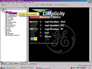
- In this section we are going to create a piece of logic in Machine Edition Logic PC and an object in Machine edition View and then store them in the toolchest for re-use later Create New project
- Choose your Template and Type in a Project Name
- It is advisable to name yourTargets to be able to easily differentiate in a multiple target environment
- Select Logic PC this where we use the PC to control attached remote I/O with logic programs residing and running on the PC
- To add logic rungs and elements we can select from the toolchest, from overhead toolbars or by typing in nemonics
- After placing the element type in a variable name. The text appears in three colours Green means an acceptable but non-existent variable, Black means an acceptable and already existing variable and red indicates an unacceptable variable
- To enter more elements select the rung and pull an element from the toolbar by drag and drop
- To create shunts, parallel rung elements, simply place the pointer at the start point of the required shunt and hold the left mouse button down drag over to the end point and let go.
- When the pointer indicator changes from a crossed circle back to a pointer you have selected an acceptable dropping point
- Here I have placed a shunt around start and placed a Normally open contact in this shunt. I have also placed a Normally closed contact and you will recognise it as a standard motor start stop circuit. By selecting the area to the left of the power bar and dragging down you can highlight the logic, having done this drag it into the toolchest and drop it. You can accept the name or type one of your own
- Now for we will create a Start Stop panel to control the motor circuit. From the Tools menu select Toolbars and then View
- Select HOME from the Graphic panels section in the Navigator window. By selecting the rectangle tool from the toolbar or right click and from the dropdown menu we will place a rectangle on our panel and we will go to the properties section to change the Fill colour
- Select a default colour or create a custom colour
- By adding more rectangles circles etc.. We can create our own custom elements from very simple to quite complex and we can use cut copy and paste as well as duplicate rotate and flip. We can also group objects together and lock them for ease of placement
- View elements that we create on a panel can have a variety of animation properties applied to them the most common is Fill animation where we can change the colour of an element as a result of a change in variables
- Now we have created a start stop panel we will select it all we can lock it together if we wish
- Now drag it into the toolchest you can keep it as a separate entry or useful to us now is to drop it right on top our previously stored logic element. This links the two together so that we can quickly re-use these items without the need to recreate the logic or the hmi object
- We are prompted for accepting overwriting
- As well as selecting Fill colour animation. We will select Touch animation which let us use our buttons (rectangles) as momentary push buttons it could be as SET RESET and other options
- We now select touch for our START variable when we selct the start button on our screen START inour logic will be activated momentarily. We will do STOP witn Touch and Fill and motor with just FILL
- Download the project and you will see the panel and if you select the START button the circle that is tied to the variable MOTOR
- This is a very simple piece of logic and animated graphics that takes moments to achieve. We can create much more complex screens by combining many animation properties an introducing external graphic images.