Weitere ähnliche Inhalte
Ähnlich wie Iaetsd emergency recovery control unit using microcontroller (20)
Mehr von Iaetsd Iaetsd (20)
Kürzlich hochgeladen (20)
Iaetsd emergency recovery control unit using microcontroller
- 1. EMERGENCY RECOVERY CONTROL UNIT
USING MICROCONTROLLER
Dhana Shree.B#1
#
Electronics and Instrumentation, Panimalar Engineering College
1shree.boopathy15@gmail.com
Abstract— ERUC is an emergency recovery unit equipped inside the car to monitor heart rate of the driver & to diagnose in the time
of danger. This paper proposed a recovery system that able to monitor and diagnose the heart beat rate condition of a person. The heart
beat rate is detected using photoplethysmograph (PPG) technique. This signal is processed using PIC16F877 microcontroller to
determine the heart beat rate per minute. Then, it sends sms alert to the mobile phone of medical experts or patient’s family members,
or their relatives via SMS. Thus, doctors can monitor and diagnose the patient’s condition continuously and could suggest earlier
precaution for the patients themselves. This will also provide a first aid unit and an automation system to prevent car accident. The
complete circuit diagram and the working model will is further below.
Keywords— heartattack, photoplethysmograph, PIC, first aid unit, Car automation Unit
I. INTRODUCTION
A volume of references speak to the terrific accidents due to heart attack while driving car.Inorder to save the patient as well as
others from a terrific accident this system was developed. This system involves four main blocks which control each and every
activity of car and the patient. They are Heart rate Monitoring unit, Processing unit, Communication unit & First aid unit. A
heartbeat sensor circuit which adopted is photoplethysmograph (PPG) technique is designed using MPLAB software. Signals
detected are then processed and analyzed before sent via sms to alert medical experts or family members. It is beneficial in terms
of cost, no complicated settings, save time and even very helpful for patient who is driving alone.
II. OBJECTIVE
A. Heart Attack:
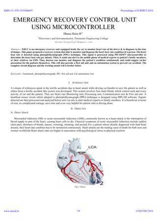
Myocardial infarction (MI) or acute myocardial infarction (AMI), commonly known as a heart attack is the interruption of
blood supply to part of the heart, causing heart cells to die. Classical symptoms of acute myocardial infarction include sudden
chest pain, shortness of breath, nausea, vomiting, sweating, and anxiety.For a patient whom already diagnosed with fatal heart
disease, their heart rate condition has to be monitored continuously. Heart attacks are the leading cause of death for both men and
women worldwide.Heart attack rates are higher in association with psychological stress or physical exertion.
Fig 1: Heart
ISBN-13: 978-1535448697
www.iaetsd.in
Proceedings of ICRMET-2016
©IAETSD 201659
- 2. A. Measuring of Heart Rate:
The pulse rate (which in most people is identical to the heart rate) can be measured at any point on the body where an artery is
close to the surface. Such places are wrist (radial artery), neck (carotid artery), elbow (brachial artery), and groin (femoral artery).
The pulse can also be felt directly over the heart. NOTE: The thumb should never be used for measuring heart rate.
III. PHOTOLETHYSMOGRAPH(PPG)
PPG is a simple and low-cost optical technique that can be used to detect blood volume changes in the micro vascular bed of
tissue. Frequently, it is used noninvasively to make measurements at the skin surface .A PPG is often obtained by using a pulse
oximeter which illuminates the skin and measures changes in light absorption. Typically, a PPG tools uses an emitter receiverpair
to determine blood flow. It consists of a matched infrared emitter and photodiode, which transmits changes in infrared reflectance
resulting from varying blood flow.
A. Circuit Working Description:
This circuit is designed to measure the heart rate. The heart rate is measured by IR transmitter and receiver.
Infrared transmitter is one type of LED which emits infrared rays generally called as IR Transmitter. Similarly IR Receiver
is used to receive the IR rays transmitted by the IR transmitter. One important point is both IR transmitter and receiver should be
placed straight line to each other. The IR transmitter and receiver are placed in the pulse rate sensor. When you want measure the
pulse rate, the pulse rate sensor has to be clipped in the finger. The IR receiver is connected to the Vccthrough the resistor which
acts as potential divider. The potential divider output is connected to amplifier section.When supply is ON the IR transmitter
passes the rays to the receiver. Depending on the blood flow, the IR rays are interrupted. Due to that IR receiver conduction is
interrupted so variable pulse signals are generated in the potential divider point which is given to A1 amplifier through the
capacitor C1. The coupling capacitor C1 is used to block the DC component because the capacitor reactance is depends on the
frequency. For DC component the frequency is zero so the reactance is infinity now capacitor acts as open circuit for DC
component. The amplifier section is constructed by the LM 324 quad operational amplifier. It consists of four independent, high
gains and internally frequency compensated operational amplifiers named as A1, A2, A3 and A4 amplifiers. The varying pulse
from the potential divider is amplified by the A1 amplifier. In this amplifier the capacitor C2 is connected in parallel with feedback
resistor to filter the any DC component in the amplified signal. If any spikes in the amplified signals, they are further filtered by
the C3 and C4 capacitors. After filtration the signal is again amplified by the A2 amplifier. Then amplified signal is given to
inverting input terminal of comparator. The comparator is constructed by the A4 amplifier in which the reference voltage is given
to non inverting input terminal. The reference voltage is generated by the A3 amplifier. Then the comparator compares the two
signal and delivered the +12v to -12v square wave pulse at its output. Then the square wave signal is given to base of the BC 557
and BC547 switching transistors in order to convert the TTL voltage 0 to 5v level. Finally the TTL output is given to MM 74C04
inverter to invert the square pulse. Then the final square wave signal is given to microcontroller or other interfacing that data is
retained even when the power is switched off. Easy Programming and Erasing are other features of PIC 16F877.
Fig 2: working description usingf PIC microcontroller
ISBN-13: 978-1535448697
www.iaetsd.in
Proceedings of ICRMET-2016
©IAETSD 201660
- 3. B. PIC
The microcontroller that has been used for this project is from PIC series. PIC microcontroller is the first RISC based
microcontroller fabricated in CMOS (complementary metal oxide semiconductor) that uses separate bus for instruction and data
allowing simultaneous access of program and data memory.
C. PIC (16F877):
Various microcontrollers offer different kinds of memories. EEPROM, EPROM, FLASH etc. are some of the memories of
which FLASH is the most recently developed. Technology that is used in pic16F877 is flash technology, so that data is retained
even when the power is switched off. Easy Programming and Erasing are other features of PIC 16F877.
D. PIC start plus programmer:
The PIC start plus development system from microchip technology provides the product development engineer with a highly
flexible low cost microcontroller design tool set for all microchip PIC micro devices. The PIC START PLUS development system
includes PIC start plus development programmer and MPlab IDE.
The PIC start plus programmer gives the product developer ability to program user software in to any of the supported
microcontrollers. The PIC start plus software running under MPlab provides for full interactive control over the programmer.
E. LCD display:
LCD display is used to display the heart rate of the driver. Crystalonics dot –matrix (alphanumeric) liquid crystal displays is
used in this paper. It is interfaced with the microcontroller through the I/O ports.
F. Communication unit(CU):
Instead of using a separate GSM modem for the communication the driver’s mobile phone itself can be interfaced with the
microcontroller and the SMS can be sent to the predefined number(s).
G. GPS system:
While sending SMS to the emergency recovery unit (AMBULANCE) the exact location of the car is must. Hence the location
in terms of latitudes & longitudes is send via the SMS. Using different signals from different satellites, the GPS software is able
to calculate the position of the receiver. GPS software performs a similar kind of exercise, using the known positions of the
satellites in space, and measuring the time that the signal has taken to travel from the satellite to Earth.
The result of at least three satellites, assuming that the clocks are all synchronized enables the software to calculate, within a
margin of error, where the device is located in terms of its latitude (East-West) and longitude (North-South) and distance from
the center of the Earth.
H.RS232:
In telecommunications, RS-232 is a standard for serial binary data interconnection between a DTE (Data terminal equipment)
and a DCE (Data Circuit-terminating Equipment). It is commonly used in computer serial ports. The standard defines the electrical
characteristics and timing of signals, the meaning of signals, and the physical size and pin out of connectors.
F.First Aid Unit(FAU):
First Aid Unit comprises of the oxygenation unit and Defibrillation.
Defibrillation
Defibrillation is the definitive treatment for the life-threatening cardiac arrhythmias, ventricular fibrillation and pulse less
ventricular tachycardia. Defibrillation consists of delivering a therapeutic dose of electrical energy to the affected heart with a
device called a defibrillator.
Closed Chest Method:
Until the early 1950s, defibrillation of the heart was possible only when the chest cavity was open during surgery. The technique
used an alternating current from a 300 or greater volt source delivered to the sides of the exposed heart by 'paddle' electrodes
ISBN-13: 978-1535448697
www.iaetsd.in
Proceedings of ICRMET-2016
©IAETSD 201661
- 4. where each electrode was a flat or slightly concave metal plate of about 40 mm diameter. The closed-chest defibrillator device
which applied an alternating current of greater than 1000 volts, conducted by means of externally applied electrodes through the
chest cage to the heart, was pioneered by Dr V. Eskin with assistance by A. Klimov in Frunze, USSR (today known as Bishkek,
Kyrgyzstan) in mid 1950.
Defibrillation
Fig 3: Defibrillation
Oxygenation unit:
As a result of heart attack, oxygen supply to different cells of the body will be reduced .Hence oxygenation is required
to prevent the cell death.
Oxygenation unit is equipped inside the car. The cylinder containing oxygen will be opened and the car cabin is provided
excess oxygen, which in turn automatically reduces increase the oxygenation. During this process all the windows of the car will
be completely sealed.
IV.CAR AUTOMATION UNIT (CAU):
Automation, in term of engineering is the usage of control system to control machinery and processes without or with
minimum human intervention. Automation enable the system to make their own decision which best suit the needs for desire
control system output. However, this does not mean that automation system exist just like that. It must be someone that create the
system and assign automation element into the system which automate the system to run automatically. The proposed
system consists of the basic blocks like transducers, microcontrollers, multiplexers and the braking, steering, acceleration systems
of the car.Sensor and the processing system: Ultrasound sensors have been used in development of the system. The ultrasound
transmitter on each side of the car.The received signal is processed by the microcontroller.TURN RIGHT, LEFT & STOP: The
two sensors which is placed in front of the car transreceives the signal. If the left side sensor detects any immovable object then
it automatically turns the car to right side.If the right side sensor detects any immovable object then it automatically turns the car
to left side.If both the side sensor detects any immovable object then it automatically stops the car on indicating it to the back
coming vehicle.
Alarm Unit:
It is activated through the relay on parallel activation with the above three units (CU, FAU & CAU).
ISBN-13: 978-1535448697
www.iaetsd.in
Proceedings of ICRMET-2016
©IAETSD 201662
- 5. V. ADVANTAGES:
First Aid
Information to relatives and Ambulance
Car automation
Even people with severe heart disease can also drive car.
Prevents from accident.
VI.CONCLUSION:
This paper is initiated to alert the family members and Recover unit (Ambulance) about patient’s heartbeat via SMS. It
fulfills the objective to detect and monitor patient’s heartbeat rate using PPG technique, interfaced with GSM & GPS modem and
sends alert to the family or/and medical experts via SMS.
Also the car is also prevented from accident.
REFERENCES
[1] S. M. Metev and V. P. Veiko, Laser Assisted Microtechnology, 2nd ed., R. M. Osgood, Jr., Ed. Berlin, Germany: Springer-Verlag, 1998.
[2] J. Breckling, Ed., The Analysis of Directional Time Series: Applications to Wind Speed and Direction, ser. Lecture Notes in Statistics. Berlin, Germany:
Springer, 1989, vol. 61.
[3] S. Zhang, C. Zhu, J. K. O. Sin, and P. K. T. Mok, “A novel ultrathin elevated channel low-temperature poly-Si TFT,” IEEE Electron Device Lett., vol. 20,
pp. 569–571, Nov. 1999.
[4] M. Wegmuller, J. P. von der Weid, P. Oberson, and N. Gisin, “High resolution fiber distributed measurements with coherent OFDR,” in Proc. ECOC’00,
2000, paper 11.3.4, p. 109.
[5] R. E. Sorace, V. S. Reinhardt, and S. A. Vaughn, “High-speed digital-to-RF converter,” U.S. Patent 5 668 842, Sept. 16, 1997.
[6] (2002) The IEEE website. [Online]. Available: http://www.ieee.org/
[7] M. Shell. (2002) IEEEtran homepage on CTAN. [Online]. Available: http://www.ctan.org/tex-archive/macros/latex/contrib/supported/IEEEtran/
[8] FLEXChip Signal Processor (MC68175/D), Motorola, 1996.
[9] “PDCA12-70 data sheet,” Opto Speed SA, Mezzovico, Switzerland.
[10] A. Karnik, “Performance of TCP congestion control with rate feedback: TCP/ABR and rate adaptive TCP/IP,” M. Eng. thesis, Indian Institute of Science,
Bangalore, India, Jan. 1999.
[11] J. Padhye, V. Firoiu, and D. Towsley, “A stochastic model of TCP Reno congestion avoidance and control,” Univ. of Massachusetts, Amherst, MA,
CMPSCI Tech. Rep. 99-02, 1999.
[12] Wireless LAN Medium Access Control (MAC) and Physical Layer (PHY) Specification, IEEE Std. 802.11, 1997.
Heart Rate Monitoring System:
[13] • Heartbeat Monitoring Alert via SMS-2009 IEEE Symposium on Industrial Electronics and Applications (ISIEA 2009)-Warsuzarina Mat
Jubadi,SitiFaridatulAisyahMohdSahak,Dept. of Electronics Engineering,UniversityTun Hussein OnnMalaysia,BatuPahat, Johor, Malaysia.
[14] • The Mobile ECG Telemonitoring System Based on GPRS and GPS-2009 International Conference on Networks Security, Wireless Communications
and Trusted Computing-Jun Zhang Electronic Department Tianjin University of Technology and Education Tianjin, China,ZhengRong Lu Sino Network
Communications Co.,Ltd Beijing, china.
[15] • M. J Drinnan, J. Allen, and A. Murray (2001)."Relation between heart rate and pulse transit time during paced respiration", Physiol. Meas.
[16] • “Range of Heart Rates per Minute and Average Heart Rate for Various Ages”. Retrieve on 7thDecember 2008
(http://www.smm.org/heart/lessons/lesson1.htm)
Car Automation:
[17] • Safety-Automation of Cars Using Embedded Microcontrollers-AbhinavRay,Varun Kumar
[18] Department of Instrumentation Technology,R.V. College of Engineering, Bangalore,India.
[19] • Ernest O. Doeblin, “Measurement systems, applications
[20] and design,” IV edition Pearson education.
[21] • J.B. Peatman, “Design with PIC microcontrollers”, PH Engineering 1998.
[22] • Crouse and Anglin, “Automotive Mechanics”, Tata McGrawHill 2002.
ISBN-13: 978-1535448697
www.iaetsd.in
Proceedings of ICRMET-2016
©IAETSD 201663