The document provides instructions for installing electric snow and ice removal systems using heated cables. It describes:
1) Applications for heated cables including ramps, balconies, parking areas, walkways and roads.
2) Detailed steps for installing heated frames and cables in concrete, asphalt or sand including proper spacing, bending radii and avoiding overlaps.
3) Recommendations for temperature controls using sensors and electronic controllers to automatically activate heating only when needed.
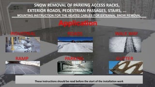
1. SNOW REMOVAL OF PARKING ACCESS RACKS,
EXTERIOR ROADS, PEDESTRIAN PASSAGES, STAIRS, ...
MOUNTING INSTRUCTION FOR THE HEATED CABLES FOR EXTERNAL SNOW REMOVAL
These instructions should be read before the start of the installation work
Application
INDUSTRIAL
GUTTERPARKINGRAMP
WALK WAYROADS
www.adibtajhiz.com
2. www.adibtajhiz.com
The ELRAMP system makes it possible to heat the ground with electric current in
order to eliminate any to the formation of ice or to favor the melting of the snow.
We recommend it especially for access ramps, balconies; parking access,
pedestrian crossings, stairs ...
The following instructions explain the installation of heated frames and rings
(heating cable) in the concrete, asphalt, cement, sand bed for ramps, stairs,
passageway, heliport, etc. ...
It is important to take into consideration the differences between the basement
area and the different coatings of the heated zone.
This snow removal equipment makes it possible to heat the ground by means of a
heated electric cable frame to prevent the formation of ice, snow, frost, or to
promote the melting of snow.
We recommend it especially for ramps, balconies; access parking, stairs, tracks
exterior, pavement or pedestrian crossings. The heating cables prevent you from
salting the tracks and saves you a lot.
3. www.adibtajhiz.com
IMPORTANT INSTALLATION INSTRUCTIONS:
• Make sure that you comply with the safety regulations in force in your country.
• Check that the contents of the delivery and the accessories correspond to what you will need.
• Order concrete or asphalt only once you are sure that all necessary materials are available.
• The insulation and resistance of the heating cable and probe must be measured before and during
installation. All measurements must be recorded on the control sheet and transmitted to EL-TRACE (
ADIBTAJHIZ ) within 30 days of installation.
• Observe the rated voltage on the rating plate of the heating elements.
• Heating cables must be laid and spread over their entire length of the installation area (sand, concrete,
asphalt, bitumen, etc.).
4. www.adibtajhiz.com
IMPORTANT INSTALLATION INSTRUCTIONS:
• Heating cables must be placed near the surface (depending on the type of coating).
• Heating cables must be installed so that there is no large unheated area.
• Do not bend or tie the heating cable.
• Heating cables must not touch, cross or overlap. The minimum distance between cables is 80 mm Do
not stretch, contract, bend or sever the heating cables.
• Do not shorten or connect the heating cable directly
.
• Only cold outlets can be shortened or extended
.
• The heating cable must not be laid in such a way as to cross.
• The heating cable must always be connected in parallel (and not series).
STEP II
5. www.adibtajhiz.com
During installation, protection by differential circuit-breaker must be provided according to force
in the country concerned.
• Heating frames or heating cables must not be placed under a welded mesh (risk of crushing).
• Monitor the installation of the floor covering to ensure that there is no mechanical which could
damage the heating cables. Appliances and tools must not be placed on the cables.
• The power of the installation must be adapted to the environment and confirmed by ELTRACE
(ADIBTAJHIZ)
• Be sure to wear shoes with suitable rubber soles in order to avoid mechanical aggression on
the heating cable.
• The lowest temperature of the heating cable installation is 5 ° C, the surface temperature
maximum is 80 ° C.
• The minimum radius of curvature is 5 times the outside diameter of the heating cable.
IMPORTANT INSTALLATION INSTRUCTIONS:
STEP III
6. www.adibtajhiz.com
• Freshly poured concrete floors must dry minimum 4 weeks in summer, see more according to temperature and
weather conditions.
• The surface to be covered should be inspected to avoid sharp edges and sharp objects damage the heating
cables.
• The heating cable and the junction box must be installed in such a way that the resistance and the ground do
not touch in the connection box.
• Cold junctions must not be bent - Cold junctions must not be left in the open air.
• Install a warning sign next to the installation and installation area of the heating cable (plan implantation).
• Install the heating cable at least 30 mm from the conductive parts of the building (eg piping water)
• Cooling conductors must pass through expansion joints, which must be protected by 2 interlaced tubes.
• The connection of several heating cables is always done in parallel in the box junction. There should be enough
ducts to accommodate the probes.
IMPORTANT INSTALLATION INSTRUCTIONS:
STEP IV
7. www.adibtajhiz.com
IMPORTANT INSTALLATION INSTRUCTIONS:
STEP V
Snow removal surfaces such as roads, bridges, driveways, exterior staircases, ramps, access of hospitals,
heliport etc, can remain practicable in winter, thanks to the system ELTRACE.
We recommend the use of the gel detector and the ELTRACE electronic control unit.
The ETO2 type is an electronic controller used for the melting of ice and snow completely automatic and
economical on exterior surfaces and in gutters.
Ice is formed the combination of low temperatures and humidity.
ETO2 detects temperature as well as humidity and the heating system
will be activated only if both parameters indicate a snow or snow ice.
Easy-to-use control panel with backlit display for quick and easy setup
in addition to a simple indication of the state, temperature, etc ...
ETO2 is suitable for controlling heating cables in 1 or 2 zones. It also exit.
8. www.adibtajhiz.com
IMPORTANT INSTALLATION INSTRUCTIONS:
Heaters or crowns are suitable for installations in concrete, screed
and sand areas (as a basis for concrete products such as pavers
and slabs).
APPLICATION: CONCRETE, PLASTER AND SAND SURFACES
TEMPERATURE CONTROL
For small installations, it is possible to use an on / off switch by checking with
the manufacturer of the switch it has the technical characteristics necessary
to ensure the proper functioning in particular in terms of power / current.
ELTRACE shall not be liable for any direct or indirect damage caused by the
malfunction of the switch.
9. www.adibtajhiz.com
IMPORTANT INSTALLATION INSTRUCTIONS:
APPLICATION: CONCRETE, PLASTER AND SAND SURFACES
Temperature control is provided by the controller in combination
with the temperature and humidity sensor proposed by ELTRACE.
The control unit must be combined with a humidity sensor and a
temperature sensor.
The control unit detects ice and snow and automatically activates
the set of the heating system. Once the system is in operation,
you will see that the zones are kept free of ice and snow.
Advantage: Automatic system, maintenance free and economical.
The outdoor heating system shall be operated only in snowy
weather or when ice or frost.
10. www.adibtajhiz.com
IMPORTANT INSTALLATION INSTRUCTIONS:
APPLICATION: CONCRETE, PLASTER AND SAND SURFACES
The ETOG probe is designed to be integrated into the surface of the
external soil to be controlled.
ETOG detects the temperature and humidity. An outdoor temperature
sensor type ETF-744/99 can be installed which measures the sudden
drop in ambient temperature.
The system will only activate when the temperature is below that selected
and that the humidity will cover the ETOG probe.
ETOG is mounted in areas where the most accumulated snow or ice is
usually found.
The probe is mounted on a base support, the upper surface flush with the
ground surface. When a surface in asphalt is installed, the probe will be
installed on a concrete base. The sensor cable must be mounted in
accordance with the regulations in force and it is advisable to use ducts.
The temperature sensor must be installed in an accessible area.
11. www.adibtajhiz.com
IMPORTANT INSTALLATION INSTRUCTIONS:
APPLICATION: CONCRETE, PLASTER AND SAND SURFACES
If your installation has more than one heating cable, make sure that the
grounding cables do not touch not the heating cables.
It is imperative to measure the resistance of each cable as well as the
insulation and ensure that they are in accordance with the requirements of
ELTRACE.
Check that the total current is less than the maximum allowable current of the
controller (and any device to which they could be connected, eg. the switch)
COLD JUNCTIONS The cold outlets connect in the junction boxes.
ATTENSION :
When connecting one or more heating frames, you must respect the
current maximum permissible level at each switching contact,
control, switch, etc.!
12. www.adibtajhiz.com
IMPORTANT INSTALLATION INSTRUCTIONS:
INSTALLATION
Installation of the electric heating system may only be carried out
by a licensed electrician in accordance with in force (EN60335-1).
The terminal connection device must be at least 3 mm between
each contact.
The frames must be connected to the network in 230V (or 400V
depending on the model used).
You will need to make sure that the frames are compatible with
the available voltage and must imperatively be controlled.
FURTHER INFORMATION :
Heating and controllers are not intended for use by persons whose physical, sensory or mental
deficiencies or lack of experience and / or knowledge on the products. Under no circumstances should
the heating system including the control system be left unattended or to children.
13. www.adibtajhiz.com
IMPORTANT INSTALLATION INSTRUCTIONS:
CHOICE OF PRODUCTS
HEATING FRAMES :
The power in W / m² is available in the product lists. The coil pitch of the heating frames is
approximately 100 to 120 mm.
HEATING CABLES:
The power in W / m is indicated on the cables and in the product list. The distance between the heating
cables may be less than 80mm. You will first have to inform your supplier to know the necessary coil
your application.
INSTALLATION OF HEATED TRAYS AND / OR CABLES:
Before installing the heating cable, you must ensure that the surface is level and free of contingent
objects (sharp pebbles, debris, etc.
The cold junctions of the heating cables are connected to the junction box and connected in parallel
with any other frames / cables.
14. www.adibtajhiz.com
IMPORTANT INSTALLATION INSTRUCTIONS:
INSULATION TEST
It is necessary to carry out insulation tests and electrical resistance of the cables / frames before and after
the installation of the coating. No guarantee will be given if these tests have not been carried out in
accordance with good practice and / or been transmitted to ELTRACE within one month after the installation
of the system.
15. www.adibtajhiz.com
IMPORTANT INSTALLATION INSTRUCTIONS:
INSTALLATION INSTRUCTION
THE FOLLOWING INSTALLATION INSTRUCTIONS ONLY CONCERN THE HEATED
FRAMES.
Place the heated frames on the floor according to the previously defined layout plan.
You can, by following the diagram below, cut the mesh into glass cloths.
DON’T CUT THE HEATING CABLE
16. www.adibtajhiz.com
POWER AND MAXIMUM DEPTH
The heated frames or cables are poured directly into the top layer such as, for example,
concrete or sand.
The cable should be placed between 35 and 100mm deep.
Depending on the geographical position (altitude, temperature <-20 ° C, ...), the power can
be adapted and defined by ELTRACE.
Make sure that the installation structure is compatible with the use of the heating cables.
17. www.adibtajhiz.com
STRUCTURE OF THE HEATED AREA FOR STONES OR PAVES
The cable or grid must be placed in a bed of sand or mortar to avoid crushing the
heating cable and comply with the structural requirements in such a way that the
frames / cables are completely covered.
The upper covering (paving stones, stone, etc.) will then be applied.
Minimum 6cm
18. www.adibtajhiz.com
FLOORING
For concrete or cement coverings. Thickness between 35 and 95 mm
1. 35-90mm concrete or cement screed
2. Raster or heating cable
3. Concrete slab
4. Floor
For structural or architectural reasons, a thicker screed may be necessary.
In that case, apply the screed in two separate layers.
Heated frames or cables shall be placed in the first layer of screed.
Then the second layer of screed is cast so that there is a minimum of 35mm
of coating thickness.
Thickness about 35mm
1. 35-90mm concrete or cement screed
2. 2. Raster or heating cable
3. 3. Concrete slab
4. 4. Floor
20. www.adibtajhiz.com
GUTTER
Frost protection is provided by a self-regulating heating cable type TRACECO-20.
drainage so that the melting water does not freeze again in the channel and
leaves the flow free.
The heating cable must resist UV (Type TRACECO-20) Care should be taken to
ensure that downspouts of rainwater are protected up to 1m deep.
EXPANSION JOINTS :
Before the project begins, you will need to determine the location and number of
expansion joints.
Warning!
Never heat through the expansion joints this could cause overheating!
1. 1 Expansion
2. 2. Heated Area
3. 3. The outer tube
4. 4. Cold lines
5. 5. Tube
21. www.adibtajhiz.com
DOCUMENTATION
The user must keep and transmit to us the following documents:
1- Description of the heating structure,
2-The plan of layout with the location of the cables or heater frames, expansion
joints, junction box, thermostat and probes (temperature, humidity).
3- The user must retain and transmit the control cards with the electrical
resistance tests and isolation .
The user of our products has full responsibility and knowledge of the products he
has chosen.
The responsibility for our products is based solely on our General Conditions of
Sale
ATTENTION
-Frames should never be cut.
-Do not cut the connection cord (cold outlet) at less than 1m before the cable mark
**** (* passage from the supply cable to the heating cable).
-Do not install at temperatures below 5 ° C.
-Follow the installation instructions.
-Protect the weft from damage.
-Heating frames can only be used with a 30mA differential circuit breaker.
22. www.adibtajhiz.com
CONTROL CARD
Power: Watt ___________
Description: ___________________________
Width: ______________________________
Power: ___________________________
Voltage: _____________________________
Connection cable: ___________________
Air conditioning
RESISTANCE OF HEATING CABLE:
-for installation: ________ Ω
- after installation: ________ Ω
ISOLATION RESISTANCE:
-for installation: ________ Ω
- after installation: ________ Ω
Last name :
First Name:
Installation Address :
Dated Signature and commercial stamp