2. Absorption spectrophotometry in the ultraviolet and visible region is
considered to be one of the oldest physical method for quantitative
analysis and structural elucidation. Absorption spectroscopy is the
spectroscopic techniques that measure the absorption of radiation,
as a function of frequency or wavelength, due to its interaction with a
sample.
Wavelength
• UV- 200-400nm
• VISIBLE- 400-800nm 2
3. Principle of Uv- Visible Spectroscopy
The Principle of UV-Visible Spectroscopy is based on the absorption of ultraviolet
light or visible light by chemical compounds, which results in the production of
distinct spectra. Spectroscopy is based on the interaction between light and matter.
When the matter absorbs the light, it undergoes excitation and de-excitation,
resulting in the production of a spectrum.
When matter absorbs ultraviolet radiation, the electrons present in it undergo
excitation. This causes them to jump from a ground state (an energy state with a
relatively small amount of energy associated with it) to an excited state (an energy
state with a relatively large amount of energy associated with it). It is important to
note that the difference in the energies of the ground state and the excited state of
the electron is always equal to the amount of ultraviolet radiation or visible
radiation absorbed by it.
4. Theory of Uv-visible spectroscopy
Ultraviolet and visible radiation interacts with matter which causes electronic
transitions (promotion of electrons from the ground state to a high energy state).
The ultraviolet region falls in the range between 190-380 nm, the visible region fall
between 380-750 nm.
The following electronic transitions are possible:
π- π* (pi to pi* transition)
n - π* (n to pi * transition)
σ - σ * (sigma to sigma * transition)
n - σ * (n to sigma * transition)
and are shown in the below hypothetical energy diagram
5. Sigma to sigma * transition (σ → σ∗)
A transition of an electron from bonding sigma orbital to higher
energy antibonding sigma orbital is designated σ → σ∗ . In alkanes,
there are only sigma bonds are available. Therefore, alkenes are
showing this type of transition. In general, sigma bonds are very
strong. Therefore, high energy is required for σ → σ∗ transition.
n to sigma * transition (n → σ∗)
n to sigma * transition (n → σ∗) involves saturated compounds with
one hetero atom like oxygen,nitrogen, fluorine, chlorine, etc.
Normally, saturated halides, alcohols, ethers, aldehyde, ketones, and
amines participate in this type of transition. These transitions require
comparatively less energy than the σ → σ∗ transition.
In saturated alkyl halides, the energy required for n to sigma *
transition (n → σ∗) decreases with the increase in the size of the
halogen atom or decrease in electronegativity of the atom. Due to
the greater electronegativity of chlorine than iodine, the n electron
on the chlorine atom is comparatively difficult to excite. The n
electrons on the iodine atom are loosely bound.
6. pi to pi star transition (π → π∗)
pi to pi *transition (π → π∗) in uv vis spectroscopy is available in
compounds with unsaturated centers like
unsaturated hydrocarbons and carbonyl compounds. It requires
lesser energy than n to sigma * transition (n → σ∗). In simple alkenes
several transitions are available but the n → π∗ transition required the
lowest energy.
n to pi * transition (n → π∗)
In n to pi * transition (n → π∗), an electron in unshared pair on a
hetero atom is excited to π∗ antibonding orbital. It involves the least
amount of energy than all types of transition in ultraviolet visible
spectroscopy. Therefore, the n → π∗ transition gives the absorption
with a longer wavelength.
In saturated ketones, n → π∗ transitions around 280 nm are the
lowest energy transition. n → π∗ is forbidden by symmetry
consideration. Thus the intensity of the band due to this transition is
low, although the wavelength is long.
7.
8. Lambert’s Law-
The amount of light absorbed is proportional to the thickness (length) of
the absorbing material (Cuvette)
Beer’s law was stated by August Beer which states that concentration and
absorbance are directly proportional to each other.
The Beer-Lambert law is expressed as:
A = εLc
where,
A is the amount of light absorbed for a particular wavelength by the sample
ε is the molar extinction coefficient. The term molar extinction coefficient
(ε) is a measure of how strongly a chemical species or substance absorbs
light at a particular ...
L is the distance covered by the light through the solution
c is the concentration of the absorbing species
Following are the limitations of Beer-Lambert law:
A diluted solution is used
There shouldn’t be a scattering of the light beam
Monochromatic electromagnetic radiation should be used
9. Deviations from Beer Lambert Law
Real Deviations – These are fundamental deviations due
to the limitations of the law itself.
Chemical Deviations– These are deviations observed due
to specific chemical species of the sample which is being
analyzed.
Instrument Deviations – These are deviations which occur
due to how the absorbance measurements are made.
10. Real Deviation-
Beer law and Lambert law is capable of describing absorption behavior of solutions
containing relatively low amounts of solutes dissolved in it (<10mM). When the
concentration of the analyte in the solution is high (>10mM), the analyte begins to
behave differently due to interactions with the solvent and other solute molecules and at
times even due to hydrogen bonding interactions.
Chemical Deviation-
Chemical deviations occur due to chemical phenomenon involving the analyte molecules
due to association, dissociation and interaction with the solvent to produce a product
with different absorption characteristics. For example, phenol red undergoes a resonance
transformation when moving from the acidic form (yellow) to the basic form (red). Due to
this resonance, the electron distribution of the bonds of molecule changes with the pH of
the solvent in which it is dissolved. Since UV-visible spectroscopy is an electron-related
phenomenon, the absorption spectrum of the sample changes with the change in pH of
the solvent.
Instrumental Deviation-
A] Due to Polychromatic Radiation (Also the reason why absorbance measurements are
taken at the wavelength of maximum absorbance λmax)
Beer-Lambert law is strictly followed when a monochromatic source of radiation exists. In
practice, however, it is common to use a polychromatic source of radiation with
continuous distribution of wavelengths along with a filter or a grating unit
(monochromators) to create a monochromatic beam from this source.
11. B] Due to Presence of Stray Radiation
Stray radiation or scattered radiation is defined as radiation from the
instrument that is outside the nominal wavelength band selected. Usually the
wavelength of the stray radiation is very different from the wavelength band
selected. It is known that radiation exiting from a monochromator is often
contaminated with minute quantities of scattered or stray radiation. Usually,
this radiation is due to reflection and scattering by the surfaces of lenses,
mirrors, gratings, filters and windows. If the analyte absorbs at the wavelength
of the stray radiation, a deviation from Beer-Lambert law is observed similar to
the deviation due to polychromatic radiation.
C] Due to Mismatched Cells or Cuvettes
If the cells holding the analyte and the blank solutions are having different
path-lengths, or unequal optical characteristics, it is obvious that there would
be a deviation observed in Beer-Lambert law. In such cases when a plot of
absorbance versus concentration is made, the curve will have an intercept k
and the equation will be defined as:
A = εbc + k
12. Choice of Solvent
The solvent cut off is the wavelength below which the solvent itself
absorbs all of the light. So when choosing a solvent be aware of its
absorbance cutoff and where the compound under investigation is
thought to absorb. If they are close, chose a different solvent.
Table .1: UV absorbance cutoffs of various common solvents
Solvent UV Absorbance Cutoff (nm)
Acetone 329
Benzene 278
Dimethylformamide 267
Ethanol 205
Toluene 285
Water 180
13. Solvent Effect-
Solvents play an important role in UV spectra. Compound peak could be
known by the solvent peak. So a most suitable solvent is one that does not
itself get absorbed in the region under investigation. A solvent should be
transparent in a particular region. A dilute solution of sample is always
prepared for analysis.
BATHOCHROMIC SHIFT. The shift of absorption to a longer wavelength
due to substitution or solvent effect (a red shift).
HYPSOCHROMIC SHIFT. The shift of absorption to a shorter wavelength
due to substitution or solvent effect (a blue shift).
Hyperchromic: an increase in the molar absorptivity.
Hypochromic: an decrease in the molar absorptivity.
16. PHOTOMETER
SPECTOPHOTOMETER
COLORIMETER
PHOTOMETER: An instrument for measuring the intensity of
light or the relative intensity of a pair of lights. Also called an
illuminometer. It utilizes filter to isolate a narrow wavelength
region. Two types of photometers are
used: spectrophotometer and filter photometer. In
spectrophotometers a monochromator (with prism or with
grating) is used to obtain monochromatic light of one defined
wavelength. In filter photometers, optical filters are used to
give the monochromatic light.
16
17. SPECTOPHOTOMETER: An instrument measures the
ratio, or a function of the two, of the radiant power of two
EM beams over a large wavelength region. It utilizes
dispersing element (Prisms/Gratings) instead of filters, to
scan large wavelength region.
17
COLORIMETER: An instrument which is used for
measuring absorption in the visible region is generally
called colorimeter.
18. 18
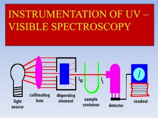
Suitable amplifier or readout device.
Detector system of collecting transmitted radiation
Sample holder or container to hold sample.
Monochromator and Filter.
Source of radiant energy.
COMPONENTS OF UV – VISIBLE SPECTROPHOTOMETER
20. 1. SOURCE OF RADIENT ENERGY
REQUIREMENTS OF AN IDEAL SOURCE
It should be stable and should not allow fluctuations.
It should emit light of continuous spectrum of high and
uniform intensity over the entire wavelength region in which
it’s used.
It should provide incident light of sufficient intensity for the
transmitted energy to be detected at the end of optic path.
It should not show fatigue on continued use.
20
21. TUNGSTEN HALOGEN LAMP
Its construction is similar to a house hold lamp.
The bulb contains a filament of Tungsten fixed in evacuated
condition and then filled with inert gas.
The filament can be heated up to 3000 k, beyond this
Tungsten starts sublimating.
It is used when polychromatic light is required. To prevent this
along with inert gas some amount of halogen is introduced
(usually Iodine).
21
22. Sublimated form of tungsten reacts with Iodine to
form Tungsten –Iodine complex.
Which migrates back to the hot filament where it
decomposes and Tungsten get deposited.
DEMERIT:
It emits the major portion of its radiant energy in
near IR region of the spectrum.
22
23. I) HYDROGEN DISCHARGE LAMP: (For ultraviolet radiation)
In Hydrogen discharge lamp pair of electrodes is enclosed in a glass
tube (provided with silica or quartz window for UV radiation to pass
trough) filled with hydrogen gas.
When current is passed trough these electrodes maintained at high
voltage, discharge of electrons occurs which excites hydrogen
molecules which in turn cause emission of UV radiations in near
UV region.
They are stable and robust.
11
24. II) Deuterium Lamp (For ultraviolet radiation)
If deuterium is used in place of hydrogen the intensity of
radiation emitted is 3 to 5 times more
The deuterium lamp is more expensive than hydrogen
lamp, but it is used when high intensity is required.
25. III) XENON DISCHARGE LAMP: (For ultraviolet radiation)
25
It possesses two tungsten electrodes separated by some distance.
These are enclosed in a glass tube (for visible) with quartz or fused
silica and xenon gas is filled under pressure.
An intense arc is formed between electrodes by applying high
voltage. This is a good source of continuous plus additional intense
radiation. Its intensity is higher than the hydrogen discharge lamp.
DEMERIT: The lamp since operates at high voltage becomes very
hot during operation and hence needs thermal insulation.
26. Mercury Arc Lamp : (For Visible radiation)
In mercury arc lamp, mercury vapor is stored under high
pressure and excitation of mercury atoms is done by electric
discharge.
DEMERIT:
Not suitable for continuous
spectral studies, (because it
doesn’t give continuous
radiations).
26
27. 27
2. FILTERS AND MONOCHROMATORS
A source is generally emitting a continuous spectra.
Therefore a device is required to select a narrow band from
wavelength of continuous spectra. For this selection filter
or monochromater or both are used.
Following types of monochromatic devices are used.
A. Filters
B. Monochromater (Prisms and Grating)
28. A light filter is a device that allow light of required
wavelength to pass but absorb light of other wavelength
wholly or partially. Thus a suitable filter can select a
desired wavelength band.
It means particular filter may be used for a specific
analysis. If analysis carried out for several species a large
number of filter have to be used and interchanged. Filter are
of two type
1. Absorption filters-
2. Interference Filter 28
A. FILTER
29. B. MONOCHROMATOR
A monochromator successfully isolate band of wavelength usually
much more than narrower filter. The essential elements for
monochromators are
• entrance slit
• Dispersing element (Grating or Prism)
• Exit slit
Material of construction should be selected with care to suit range
in which it has to work , e. g. normal glass for visual range, quartz
for ultraviolet and alkali halides for IR region
30. # Prism
Prism is made from glass, Quartz or fused silica. Quartz
orfused silica is the choice of material
of UV spectrum.
When white light is passed through glass prism, dispersion of
polychromatic light in rainbow occurs. Now by rotation of the
prism different wavelengths of the spectrum can be made to
pass through in exit slit on the sample.
The effective wavelength depends on the dispersive power of
prism material and the optical angle of the prism.
30
32. • There are two types of mounting in an instrument one is called
‘Cornu type’(refractive), which has an optical angle of 60o and its
adjusted such that on rotation the emerging light is allowed to fall
on exit slit.
• The other type is called “Littrow type”(reflective), which has
optical angle 30o and its one surface is aluminized with reflected
light back to pass through prism and to emerge on the same side of
the light source i.e. light doesn’t pass through the prism on other
side.
32
33. # GRATING
Are most effective one in converting a polychromatic light to
monochromatic light. It consist of a large number of parallel lines
(grooves) ruled on a highly polished surface such as alumina.
Generally 15,000 to 30,000 lines per square inch are drawn for UV
and Visible region
33
34. When light rays are impinged on the grating its grooves act as
scattering center for light rays. Thus the light deffracted or spread
out over a range of angle and in certain direction, reinforcement or
constructive interference may take place.
Generally grating are difficult to be prepared. Therefore replica
grating are prepared from original grating. This is done by coating
the original grating with film of an epoxy resin which is after
setting is removed to yield replica.
34
35. Grating gives higher and linear dispersions compared to prism
monochromator.
Can be used over wide wavelength ranges.
Gratings can be constructed with materials likes
aluminium which is resistant to atmospheric moisture.
Provide light of narrow wavelength.
No loss of energy due to absorption.
35
36. Comparison Prism Grating
Made of Glass-: Visible
Quartz/fused silica-: UV
Alkali halide:- IR
Grooved on highly polished
surface like alumina.
Working Principle Angle of Incident Law of diffraction
nλ= d (sini±sinθ)
Merits/demerits Prisms give non-liner
dispersion hence no
overlap of spectral order.
It can’t be used over
consideration wavelength
ranges.
Prisms are not sturdy and
long lasting.
Grating gives liner dispersion
hence overlap of spectral
order.
It can be used over
considerable wavelength
ranges.
Grating are sturdy and long
lasting
36
37. The cells or cuvettes are used for handling liquid samples.
The cell may either be rectangular or cylindrical in nature.
For study in UV region; the cells are prepared from quartz or
fused silica whereas color corrected fused glass is used for
visible region.
The surfaces of absorption cells must be kept scrupulously
clean. No fingerprints or blotches should be present on cells.
Cleaning is carried out washing with distilled water or with
dilute alcohol, acetone.
37
39. Device which converts light energy into electrical signals, that
are displayed on readout devices.
The transmitted radiation falls on the detector which
determines the intensity of radiation absorbed by sample
The following types of detectors are employed in instrumentation
of absorption spectrophotometer
1. Barrier layer cell/Photovoltaic cell
2. Phototubes/ Photo emissive tube
3. Photomultiplier tube
39
40. Requirements of an ideal detector:-
It should give quantitative response.
It should have high sensitivity and low noise level.
It should have a short response time.
It should provide signal or response quantitative to wide
spectrum of radiation received.
40
41. The detector has a thin film metallic layer coated with silver or
gold and acts as an electrode.
It also has a metal base plate which acts as another electrode.
These two layers are separated by a semiconductor layer of
selenium.
41
42. When light radiation falls on selenium layer, electrons become
mobile and are taken up by transparent metal layer.
This creates a potential difference between two electrodes &
causes the flow of current.
When it is connected to galvanometer, a flow of current
observed which is proportional to the intensity and wavelength
of light falling on it.
42
45. Consists of a evacuated glass tube with a photocathode and a
collector anode.
The surface of photocathode is coated with a layer of elements
like cesium, silver oxide or mixture of them.
When radiant energy falls on photosensitive cathode, electrons
are emitted which are attracted to anode causing current to
flow.
More sensitive compared to barrier layer cell and therefore
widely used.
45
46. The principle employed in this detector is that, multiplication
of photoelectrons by secondary emission of electrons.
46
In a vacuum tube, a primary photo-cathode is fixed which
receives radiation from the sample.
Some eight to ten dynodes are fixed each with increasing
potential of 75-100V higher than preceding one.
Near the last dynode is fixed an anode or electron collector
electrode.
Photo-multiplier is extremely sensitive to light and is best
suited where weaker or low radiation is received
48. Depending upon the monochromators (filters or dispersing
device) used to isolate and transmit a narrow beam of radiant
energy from the incident light determines whether the
instrument is classified as Photometer or a Spectrophotometer.
Spectrophotometers used here detects the percentage
transmittance of light radiation, when light of certain
intensity & frequency range is passed through the sample.
Both can be a single beam or double beam optical system.
48
49. • Light from the source is carried through lens and/or through
aperture to pass through a suitable filter.
• The type of filter to be used is governed by the colour of the
solution.
• The sample solution to be analysed is placed in cuvettes.
49
51. After passing through the solution, the light strikes the surface
of detector (barrier-layer cell or phototube) and produces
electrical current.
51
The output of current is measured by the deflection of needle
of light-spot galvanometer or micro ammeter. This meter is
calibrated in terms of transmittance as well as optical density.
The readings of solution of both standard and unknown are
recorded in optical density units after adjusting instrument to a
reagent blank.
53. 53
Advantage of single beam spectrophotometer
Cheap
Easy to construct
Disadvantage
Any fluctuation in the intensity of radiation sources affects the
absorbance.
Continuous spectrum is not obtained.
54. Double beam instrument is the one in which two beams are
formed in the space by a U shaped mirror called as beam
splitter or beam chopper .
54
Chopper is a device consisting of a circular disc. One third of
the disc is opaque and one third is transparent, remaining one
third is mirrored. It splits the monochromatic beam of light
into two beams of equal intensities.
57. 57
Advantages of double beam spectrophotometer
It facilitates rapid scanning over wide λ region.
Fluctuations due to radiation source are minimised.
It doesn’t require adjustment of the transmittance at 0% and 100%
at each wavelength.
It gives ratio of intensities of sample & reference beams
simultaneously.
Disadvantages:-
Construction is complicated.
Instrument is expensive.
59. 2 Radiant energy intensity
changes with fluctuation
of voltage.
It permits a large degree
of inherent
compensation for
fluctuations in the
intensity of the radiant
energy.
3 It measure the total
amount of transmitted
light reaching the detector
It measures the
percentage of light
absorbed by the sample.
59
60. 4 In single beam it’s not
possible to compare blank
and sample together.
In double beam it’s
possible to do direct one
step comparison of sample
in one path with a standard
in the other path.
5 In single beam radiant
energy wavelength has to
be adjusted every time.
In this scanning can be
done over a wide
wavelength region
6 Working on single beam is
tedious and time
consuming.
Working on double beam is
fast and non tedious.
60
61. Applications of Uv-visible Spectroscopy
1. Detection of Impurities-
Uv- absorption spectroscopy is one of the best methods for
determination of impurities in organic compounds. Additional peaks can be
observed due to impurities in the sample and it can be compared with that
of standard. By also measuring the absorbance at specific wavelength, the
impurities can be detected.
2.Structural elucidation of organic compounds
Uv-spectroscopy is useful in the structure elucidation of organic
compounds, the presence or absence of unsaturation, the presence of
heteroatoms. From location of peaks and combination of peaks, it can be
concluded that whether the compound is saturated or unsaturated, hetero
atoms are present or not.
62. 3.Quantitative analysis
Uv-spectroscopy can be used for quantitative
determination of compounds that absorb uv radiation.
4. Qualitative analysis
Uv- absorption spectroscopy can characterize those
types of compounds which absorb uv-radiation.
Identification is done by comparing the absorption
spectrum with the spectra of known compounds.
5. Chemical kinetics
Kinetics of reaction can also be studied by using uv-
spectroscopy. The uv radiation is passed through the
reaction cell and the absorbance changes can be
observed.
6.Detection of functional groups
This technique is used to detet the presence or absene
of functional group.