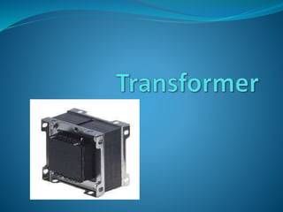
Transformer
- 2. Introduction Transformer is a static device which transforms electrical energy from one circuit to another without any direct electrical connection and with the help of mutual induction between two windings. It transforms power from one circuit to another without changing its frequency but may be in different voltage level.
- 3. Principle The main principle of transformer is mutual induction formed between two coils. A transformer basically is very simple electro- magnetic passive electrical device that works on the principle of Faraday’s law of induction by converting electrical energy from one value to another….
- 4. Mutual Induction When current in the primary coil changes being alternating in nature, a changing magnetic field is produced and is associated with the secondary coil through the soft iron core. Hence magnetic flux linked with the secondary coil changes. Which induces e.m.f. in the secondary. This is known as mutual induction.
- 5. Purpose of transformer The main purpose of transformer is either to step up (or) step down the input input a.c power. Transformer Step up Transformer Step down Transformer
- 6. Structure Step up transformer Step down transformer Primary winding: Less Secondary winding: More Primary winding: More Secondary winding: Less
- 7. Classification of Transformer The transformers are classified based on the Performance Construction Output voltage Application Cooling factor Input supply
- 8. Based on performance Power Transformer(transmission&distribution) Current Transformer(instrument transformer) Potential Transformer(instrument transformer Based on construction core type transformer Shell type transformer Berry type transformer
- 9. Based on output voltage Step up transformer Step down transformer Auto transformer Based on application Welding transformer Furnace transformer
- 10. Based on cooling factor Duct type transformer Oil immersed Based on input supply Single phase transformer Three phase transformer
- 11. Ideal transformer Zero leakage flux: -Fluxes produced by the primary and secondary currents are confined within the core The windings have no resistance: - Induced voltages equal applied voltages The core has infinite permeability - Reluctance of the core is zero - Negligible current is required to establish magnetic flux Loss-less magnetic core - No hysteresis or eddy currents
- 12. V1 – supply voltage ; I1- noload input current ; V2- output voltgae; I2- output current Im- magnetising current; E1-self induced emf ; E2- mutually induced emf Ideal transformer on no load condition
- 13. Practical Transformer Normally ,it produces both hysteresis and eddy current loss. when it’s subjected to alternating flux. To control this losses......... High grade silicon steel for hysteresis loss The core is designed with a thin limination for eddy current loss.
- 14. Practical transformer on no load condition The I0 lags from the voltage v1 at the angle of φ0
- 15. Transformer on load condition Connecting a external device to the secondary side of the transformer is known as loaded condition. When the current I2 flows through the secondary side the magnitude and phase of I2 is determined by the load At inductive load:I2 lags V2 At capacitance load :I2 leads V2 At resistive load :I2 in phase with V2
- 16. The secondary coil creates a flux called as φ2 this generated flux opposes the main flux formed in the core. This kind of mmf is known as demagnetising ampere-turn. Due to this the main flux gets reduced. So ,the induced e.m.f in the primary coil as gets reduced.
- 17. Tertiary winding The process of providing additional winding in the transformer in known as tertiary winding. It is placed in between the primary and secondary winding. The transformer which uses teritary winding are known as 3winding transformer.
- 18. Principle The third winding is connected in a delta structure. The principle of this winding is to be when a fault occurs in the primary and secondary winding. During the time of fault, there is a large imbalance in the phase voltage so to equalise this problem tertiary winding is used and the current is being circulated. In this condition to avoid overheating copper is used.
- 19. Purpose of tertiary winding The main purpose of tertiary winding is to supply additional load to the secondary side of the transformer. It’s used as voltage coil in the testing transformer. Interconnection of different voltage system into a single supply is known as three winding transformer.
- 20. Stabilization of 3 winding transformer
- 22. Usage It’s used in power transformer. It’s used to eliminate the third harmonics current level from the transformer. These harmonics are produced due to the high flux densities in the core.
- 23. Advantages of tertiary winding It reduces the unbalancing in the primary coil. It redistributes the flow of fault current. The supplied load are in different voltage level. To satisfy this the load is taken from the terinary winding. It is designed in the form of delta.
- 24. Disadvantages of tertiary winding The construction of tertiary winding is very difficult when compared to the normal transformer. It requires large amount of copper to the heating level in the transformer. It occupies huge area for the placement of the transformer.