![56
D
b
d
x
s
yd
yd
s
E
f
=
≥ε
ε
Strain
AS
0035
.
0
=
cu
ε
X-section
u
M
cd
f cd
f
c
C x
b
f
C cd
c .
.
8
.
0
=
yd
s
s f
A
T .
=
u
M
s
T
x
y 8
.
0
=
Parabola-rectangle
Stress block
Equivalent rectangle
Stress block
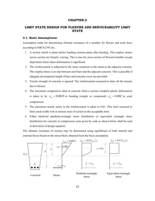
3.2. Design Equations for Singly Reinforced Rectangular Section:
Consider a singly reinforced rectangular section subjected to a factored load moment, u
M as
shown below.
-Equilibrium of both internal and external forces,
i) [ ] s
c
H T
C
F =
⇒
=
∑ 0
yd
s
cd f
A
x
b
f .
.
.
8
.
0 =
⇔ Let
d
b
As
.
=
ρ --steel ratio of section
yd
cd f
d
b
x
b
f .
.
.
.
.
8
.
0 ρ
=
⇔
Simplifying, depth of neutral axis obtained as,
d
f
f
x
cd
yd
.
8
.
0
.
⎟
⎟
⎠
⎞
⎜
⎜
⎝
⎛
=
ρ
(1)
ii) [ ] z
T
z
C
M
M s
c
u .
.
0 =
=
⇒
=
∑ Where ( )
x
d
z 4
.
0
−
= --lever arm
-taking moment about s
T :
z
C
M c
u .
=
( ) ( )
x
d
x
b
f
M cd
u 4
.
0
.
.
.
8
.
0 −
=
⇔
Substituting x from Eq.(1),
⎟
⎟
⎠
⎞
⎜
⎜
⎝
⎛
−
⎟
⎟
⎠
⎞
⎜
⎜
⎝
⎛
=
⇒ d
f
f
d
d
f
f
b
f
M
cd
yd
cd
yd
cd
u .
8
.
0
.
4
.
0
.
.
8
.
0
.
.
.
8
.
0
ρ
ρ
Simplifying, ultimate moment of resistance of section is obtained as,
⎟
⎟
⎠
⎞
⎜
⎜
⎝
⎛
−
=
cd
yd
yd
u
f
f
d
b
f
M
2
.
1
.
.
.
. 2
ρ
ρ (2)
( )
x
d
z 4
.
0
−
=](data:image/gif;base64,R0lGODlhAQABAIAAAAAAAP///yH5BAEAAAAALAAAAAABAAEAAAIBRAA7)
Empfohlen
Weitere ähnliche Inhalte
Ähnlich wie CHAPTER 3.LIMIT STATE DESIGN FOR FLEXURE AND SERVICEABILITY .pdf
Ähnlich wie CHAPTER 3.LIMIT STATE DESIGN FOR FLEXURE AND SERVICEABILITY .pdf (20)
Kürzlich hochgeladen
Kürzlich hochgeladen (20)
CHAPTER 3.LIMIT STATE DESIGN FOR FLEXURE AND SERVICEABILITY .pdf
- 1. 55 0035 . 0 = cu ε 002 . 0 0 = ε d x c cu cd f f γ 67 . 0 = c cu cd f f γ 67 . 0 = y= 0.8x yd s f f = yd s f f = Strain Parabola-rectangle stress Equivalent-rectangle stress yd s ε ε ≥ x-section A N. s A CHAPTER-3 LIMIT STATE DESIGN FOR FLEXURE AND SERVICEABILITY LIMIT STATE 3.1. Basic Assumptions: Assumption made for determining ultimate resistance of a member for flexure and axial force according to EBCS-2/95 are, 1. A section which is plane before bending remains plane after bending. This implies strains across section are linearly varying. This is true for most section of flexural member except deep beam where shear deformation is significant. 2. The reinforcement is subjected to the same variations in the strain as the adjacent concrete. This implies there is no slip between steel bars and the adjacent concrete. This is possible if adequate development length of bars and concrete cover are provided. 3. Tensile strength of concrete is ignored. The reinforcement assumed to takes all the tension due to flexure. 4. The maximum compressive stain in concrete when a section complete plastic deformation is taken to be 0035 . 0 = cu ε in bending (simple or compound) 002 . 0 = cu ε in axial compression 5. The maximum tensile strain in the reinforcement is taken to 0.01. This limit assumed to limit crack-width with in tension zone of section to the acceptable limit. 6. Either idealized parabola-rectangle stress distribution or equivalent rectangle stress distribution for concrete in compression zone given by code as shown below shall be used in derivation of design equation. The ultimate resistance of section may be determined using equilibrium of both internal and external forces based on the stress block obtained from the basic assumption.
- 2. 56 D b d x s yd yd s E f = ≥ε ε Strain AS 0035 . 0 = cu ε X-section u M cd f cd f c C x b f C cd c . . 8 . 0 = yd s s f A T . = u M s T x y 8 . 0 = Parabola-rectangle Stress block Equivalent rectangle Stress block 3.2. Design Equations for Singly Reinforced Rectangular Section: Consider a singly reinforced rectangular section subjected to a factored load moment, u M as shown below. -Equilibrium of both internal and external forces, i) [ ] s c H T C F = ⇒ = ∑ 0 yd s cd f A x b f . . . 8 . 0 = ⇔ Let d b As . = ρ --steel ratio of section yd cd f d b x b f . . . . . 8 . 0 ρ = ⇔ Simplifying, depth of neutral axis obtained as, d f f x cd yd . 8 . 0 . ⎟ ⎟ ⎠ ⎞ ⎜ ⎜ ⎝ ⎛ = ρ (1) ii) [ ] z T z C M M s c u . . 0 = = ⇒ = ∑ Where ( ) x d z 4 . 0 − = --lever arm -taking moment about s T : z C M c u . = ( ) ( ) x d x b f M cd u 4 . 0 . . . 8 . 0 − = ⇔ Substituting x from Eq.(1), ⎟ ⎟ ⎠ ⎞ ⎜ ⎜ ⎝ ⎛ − ⎟ ⎟ ⎠ ⎞ ⎜ ⎜ ⎝ ⎛ = ⇒ d f f d d f f b f M cd yd cd yd cd u . 8 . 0 . 4 . 0 . . 8 . 0 . . . 8 . 0 ρ ρ Simplifying, ultimate moment of resistance of section is obtained as, ⎟ ⎟ ⎠ ⎞ ⎜ ⎜ ⎝ ⎛ − = cd yd yd u f f d b f M 2 . 1 . . . . 2 ρ ρ (2) ( ) x d z 4 . 0 − =
- 3. 57 The same equation of ultimate moment of resistance of section can be obtained if moment center is taken at c C . -Defining the ultimate moment and relative steel-area using the following dimension-less parameters: 2 . . d b f M cd u = μ --relative ultimate moment And cd yd f f . ρ ω = --mechanical reinforcement ratio Then, neutral-axis depth obtained in Eq.(1) can be written as, 8 . 0 . d x ω = (1a) Therefore, depth of equivalent stress-block is obtained as, d x y . 8 . 0 ω = = Writing equation of moment of resistance of section in the form as shown below by rearranging Eq.(2), ⎟ ⎟ ⎠ ⎞ ⎜ ⎜ ⎝ ⎛ − = cd yd cd yd cd u f f f f d b f M 2 . 1 . . . . 2 ρ ρ Writing the above equation in terms of dimension less parameters, 2 2 1 . 2 ω ω ω ω μ − = ⎟ ⎠ ⎞ ⎜ ⎝ ⎛ − = ⇒ (2a) Rearranging Eq.(2a), 0 2 2 2 = + − ⇒ μ ω ω Solving for ω , μ ω 2 1 1 − − = (3) Therefore, area of tension steel required to resist the ultimate moment, u M is obtained by taking moment about c C as, z T M s u . = z f A M yd s u . . = ⇔ Where ( ) x d z 4 . 0 − = substituting x from Eq.(1a) and ω from Eq.(3) ( ) μ ω 2 1 1 . 2 . 2 1 − + = ⎟ ⎠ ⎞ ⎜ ⎝ ⎛ − = d d z
- 4. 58 Rearranging, the required area of tension steel is obtained by, z f M A yd u s . = (4) 3.2.1. Balanced Singly Reinforced Section In balanced section, yielding of tension steel and crushing of concrete takes place at same time when the section complete plastic deformation. That is, the maximum compressive strain in concrete reaches the ultimate strain, 0035 . 0 = = cu c ε ε and the strain in tension steel is just yielded, s yd yd s E f = = ε ε . From strain distribution, using similarity of triangles, s cu cu d x ε ε ε + = Substituting b x x = & s yd yd s E f = = ε ε , the balanced neutral-axis depth is obtained as, ( ) d E f x s yd cu cu b . + = ε ε (5) Where 0035 . 0 = cu ε --ultimate compressive strain of concrete Equating b x with equation of neutral-axis depth obtained in Eq.(1) and Eq.(1a), the balanced reinforcement ratio and the balanced mechanical reinforcement ratio are obtained as, ( ) yd cd s yd cu cu b f f E f . 8 . 0 + = ε ε ρ (6) And ( ) s yd cu cu b E f + = ε ε ω 8 . 0 (7) If b ρ ρ < , the steel yields first at the load near collapse (a case of under-reinforced section and ductile-type failure). If b ρ ρ > , crushing of concrete takes place first prior to yielding of tension steel at the load near collapse (a case of over-reinforced section and brittle-type failure). To ensure ductility, in practice the maximum amount of tension steel is fairly below the amount corresponding to the balanced-one.
- 5. 59 ACI:318 code recommend: maximum reinforcement ratio ensuring ductility as b ρ ρ 75 . 0 max = . For seismic load resisting member, the same code recommends, b ρ ρ 5 . 0 max = . Based on ACI recommendation ( b ρ ρ 75 . 0 max = ), maximum design constants of singly reinforced section are obtained as shown in table below. Table: Maximum design constants of singly reinforced section (ACI-code) EBCS:2/95 recommend: the maximum amount of tension steel used to ensure ductility is based on limiting the neutral-axis depth at, d x 448 . 0 max = --for no redistribution of elastic moments d x 368 . 0 max = --for 10% redistribution of elastic moments d x 288 . 0 max = --for 20% redistribution of elastic moments d x 208 . 0 max = --for 30% redistribution of elastic moments Based on EBCS-2/95 recommendation, maximum design constants of singly reinforced section are obtained as shown in table below. Table: Maximum design constants of singly reinforced section (EBCS-2/95 code) Steel Grade max ω max μ S-300 MPa S-400 MPa S-460 MPa 0.437 0.401 0.382 0.341 0.320 0.309 % Redistribution of elastic moments max ω max μ 0% 10% 20% 30% 0.3584 0.2944 0.2304 0.1664 0.294 0.251 0.204 0.152
- 6. 60 Better approach as follows: In accordance with LSD method, at ULS of collapse:- • εc approaches εcu = 0.0035 • The reinforcing steel shall yield first ( s yd d y E f = ε ) ⇒ Ductility is ensured by means of under reinforcement. • At balanced failure simultaneous failure of the two materials (Concrete & Steel) occurs. Let x b be the depth to the NA at balanced failure. From the strain relation, yd b cu b x d x ε ε − = ⇒ yd cu cu b d x ε ε ε + = * • If x < x b ⇒ Steel yields first • If x > x b ⇒ Crushing of concrete takes place first. Σ FH = 0 ⇒ Ts = CC ⇒ As fyd = 0.8 xb b fcd Substituting for xb and simplifying, yd cd yd cu cu b f f * * 8 . 0 ε ε ε ρ + = (a steel ratio for balanced case) However, for ductility purpose the steel ratio ρ may range b/n 0.75 ρb to 0.9 ρb, and in some cases as low as 0.5 ρ b in ACI code, but in EBCS-2 ductility is ensured by keeping kx max = 0.448 for 0% redistribution or even less for redistribution > 0% . Rewriting the force equilibrium byfcd = As fyd ⇒ b * 0.8x fcd = ρbd fyd , * 8 . 0 * m f f d x k cd yd x ρ ρ = = = Where cd yd f f m * 8 . 0 = Σ Mc = 0 ⇒ Md = As fyd (d - 0.4x) Substituting the value of x and simplifying Md = 0.8 bd2 fcd kx (1-0.4 kx)
- 7. 61 l When the above equation is solved for kx, max 2 2 2 1 1 4 5 . 0 x d x k c bd M c c k ≤ ⎭ ⎬ ⎫ ⎩ ⎨ ⎧ − − = Where c1 = 2.5/m, c2 = 0.32m2 fcd, m=fyd/(0.8fcd) kx max = 0.448 for 0% redistribution. The section capacity for single reinforcement case may be computed from Σ Mt = 0, when kx < kx max ⇒ Mu = 0.8bx fcd (d-0.4x) x = kx max d = 0.8bd2 fcd kx max (1 -0.4 kx max) 3.2.2. Inelastic Redistribution of Moments in Continuous-beams and Frames When statically indeterminate beam is loaded beyond the working loads, plastic hinges forms at the location of maximum bending moment. On further loading the beam, the maximum moment do not increase beyond the ultimate moment capacity of section of beam, however, rotation at plastic hinges keep on increasing until the ultimate rotation capacity is reached. A redistribution of moment takes place with the changes in the moment elsewhere in the beam as if a real hinges are existing. With further increase of additional plastic hinge, redistribution moments continue until a collapse mechanism is produced. Plastic analysis can be applied in analysis of steel structures. However, its use for analysis of reinforced concrete structures is limited. A limited redistribution of moments obtained from elastic analysis of indeterminate structures is permitted by most codes if members are designed under-reinforced section provided equilibrium is maintained under each combination of ultimate loads. For illustration of plastic analysis of structure, consider a fixed-beam, which is statically indeterminate, subjected to increasing uniform load shown below. w Let the beam subjected to the load ' ' p w that cause the plastic hinges at the ends when the maximum moment at supports equal to the ultimate resistance of beam section. But, with the
- 8. 62 l ( ) cd yd yd u p n f f d b f M l w M 2 . 1 . . . 12 . 2 2 ρ ρ − = = = 12 . 2 l wp 24 . 2 l w M p p = Plastic hinge u M u M 12 . 2 l w M M p u n = = 12 . 2 l wp 12 . 8 . 24 . 2 2 2 l w l w l w M M p p u p = ⎟ ⎟ ⎠ ⎞ ⎜ ⎜ ⎝ ⎛ Δ + = = u M u M Collapse Mechanism u M ) (− ) (− ) (+ ) (+ ) (− ) (− formation of plastic hinges, the beam is still able to support additional load without complete collapse. After formation of plastic hinges at supports, the beam behaves as if simply supported. p w On further loading, the moment at center of span increases proportionally with the change of loading. Additional load w Δ is slowly applied until it causes the beam to transform into a collapse mechanism with the formation of one or more hinges at the middle. w w w p u Δ + = At collapse, mid-span moment equal to the ultimate resistance of beam section, 12 . 8 . 24 . 2 2 2 l w l w l w M p p u = Δ + = Equating negative and positive collapse moment, additional load that causes collapse mechanism in terms of the load ' ' p w that causes the plastic hinges at the ends is, 3 p w w = Δ And, collapse load in terms of ' ' p w p p p p u w w w w w w 3 4 3 = + = Δ + = These shows, the beam may carry a load of p w 3 4 with redistribution. The ultimate moment in terms of ultimate load is:
- 9. 63 12 . 2 l w M p u = Substituting u p w w 4 3 = ( ) 16 . 12 . 4 3 2 2 l w l w M u u u = = → If elastic analysis is made using the ultimate load ' ' u w , the maximum moment at support is 12 . 2 l wu . The percentage reduction in bending is: % 25 100 12 . 16 . 12 . 2 2 2 = − x l w l w l w u u u Plastic analysis of continuous beams and frames also can be done using virtual work method. Assume any reasonable collapse mechanism, equating internal work done by ultimate moments at plastic hinges with external work done by collapse load on deflecting collapsed span of continuous beam and frame, the location of plastic hinges and the minimum collapse load can be determined. According to EBCS-2/95, elastic moments of continuous beams and frames are redistributed using the following reduction coefficient, δ 1) For continuous beams and rigid jointed braced frames with span/effective depth ratio not greater than 20, ⎟ ⎠ ⎞ ⎜ ⎝ ⎛ + = d x 25 . 1 44 . 0 δ Where x—is calculated at ultimate limit state Based on the above equation, the limiting maximum neutral axis depth ratio used for proportioning of sections of continuous beams and rigid jointed braced frames are obtained as follow: For 30% redistribution of elastic moment, 208 . 0 = d x For 20% redistribution of elastic moment, 288 . 0 = d x For 10% redistribution of elastic moment, 368 . 0 = d x For no reduction of elastic moment, 448 . 0 = d x 2) For other continuous beams and rigid braced frames 75 . 0 ≥ δ 3) For sway frames with slenderness ratio l of columns less than 25 90 . 0 ≥ δ
- 10. 64 Examples on Design of Singly Reinforced Beams using Limit State Design Method
- 11. 65
- 12. 66
- 13. 67
- 14. 68
- 15. 69
- 16. 70
- 17. 71
- 18. 72
- 19. 73
- 20. 74
- 21. 75
- 22. 76
- 23. 77
- 24. 78
- 25. 79
- 26. 80
- 27. 81
- 28. 82 Assignment-1: Question No. 4 Question No. 6 Question No. 8
- 29. 83 Exercise-1
- 30. 84 b d yd ε AS cu ε 1 s A 1 d max x x x b = = 1 s ε ≡ + cd f cd f u M 1 M 2 M max max x y = ) ( 1 d d − s C c C c C yd s s f A T . = yd s f A T . 1 1 = yd s f A T . 2 2 = a) x-section b) Strain c) stresses, doubly reinforced section, u M d) Stresses, balanced section, 1 M e) stresses, excess tension- steel plus comp. steel, 2 M 3.3. Doubly Reinforced Rectangular Section Consider a doubly reinforced rectangular section subjected to an ultimate moment, u M as shown below. Design equations are derived by dividing the section into two parts: Balanced singly reinforced section and excess tension steel plus compression steel. It is assumed that both tension and compression steels are yielded. The excess tension steel and compression steel are proportioned in such a way that the neutral axis is maintained at balanced position. yd s s f A C . 1 = Let 1 M --moment capacity of balanced singly reinforced section 2 M --moment resistance provided by excess tension steel plus compression steel Thus, the total ultimate moment of resistance of doubly reinforced section is the sum of the two parts: moment capacity of balanced singly reinforced section, 1 M and ultimate moment resisted by excess tension steel plus compressive steel, 2 M . i.e ( ) 2 1 M M Mu + = Moment capacity of balanced singly reinforced section, 2 max 1 . . . d b f M cd μ = And, the corresponding area of tension steel balancing 1 M is, min 1 1 . z f M A yd s = Where ( ) ⎟ ⎠ ⎞ ⎜ ⎝ ⎛ − = − = 2 1 . 4 . 0 max max min ω d x d z Excess moment to be resisted by excess tension steel plus compression steel is, ( ) 1 2 M M M u − =
- 31. 85 Equating excess moment with the couple made by internal forces in excess tension steel and compression steel as shown in Fig.(e), area of excess tension steel and compression steel are obtained as (if compression steel yielding) ( ) 1 2 2 . d d f M A yd s − = And, ( ) 1 2 1 . d d f M A yd s − = Therefore, the total area of tension steel required by doubly reinforced section, 2 1 s s s A A A + = To check yielding of compression steel, referring to stain diagram in Fig.(b), the strain in compression steel is determined and compared with the yield strain of a given steel as obtained below. ( ) 1 1 max s cu cu d x ε ε ε − = ( ) max 1 max 1 . x d x cu s − = ⇒ ε ε Where 0035 . 0 = cu ε ( ) 8 . 0 . 8 . 0 max max max d y x ω = = If compression steel is yielding, s yd yd s E f = ≥ ε ε 1 & yd s f f = 1 (as assumed) Or, if compression steel is not yielding, s yd yd s E f = < ε ε 1 & yd s s s f E f < = 1 1 . ε Then, area of compression steel is re-determined using, ( ) ( ) 1 1 2 1 1 2 1 . . . d d E M d d f M A s s s s − = − = ε Another Similar approach: Assume that As & As1 are stressed to fyd. Mu = Muc+ Musc Where Muc is the BM carried by the concrete and partial area of tensile steal. ⇒ Muc = 0.8bd2 fcd k1 (1-0.4 k1)
- 32. 86 In which k1 = kx max, the maximum steel ratio corresponding to single reinforcement section in case of design and max 1 1 x s s k bd A A k ≤ − = for the case of analysis. Musc is the BM carried by compressive steel and the corresponding tensile steel. Musc = As1 fyd (d-dc’) The yielding of the compressive steel may be checked from the strain relation as yd cu c sc x d x ε ε ε ≥ − = * '
- 33. 87 Examples on Design of Doubly Reinforced Beams using Limit State Design Method
- 34. 88
- 35. 89
- 36. 90
- 37. 91
- 38. 92
- 39. 93
- 40. 94
- 41. 95
- 42. 96
- 43. 97 3.4. Flanged Section (T- or L-section) under Flexure The general discussion with respect to flanged section, effective width of flange in working stress method holds for strength limit state method as well. In treating flanged section using strength limit state method, it is convenient to adopt the same equivalent rectangle stress-block that is used for rectangular cross section. i) If depth of equivalent rectangle stress-block, ' ' y is equal to or less than the flanged thickness, ' ' f h (i.e f h y≤ ), a flanged section may be treated as a rectangular section of width equal to an effective width of flange, ' ' e b provided the flange of section is on compression side when the section subjected a moment. For trial purpose initially, it can be assumed the stress block is with-in the flange (or assume flanged section rectangular with width equal to effective width of flange). -calculate relative ultimate moment and relative mechanical steel ratio of assumed rectangular section using, 2 . . d b f M e cd u = μ And μ ω 2 1 1 − − = -then, compute depth of equivalent rectangle stress-block for assumed section and compare with thickness of the flange of the section, d y . ω = -If f h y ≤ , the section is designed as rectangular section with width equal to effective width of flange, ' ' e b . Therefore, area of tension steel required by the section for such case is given by z f M A yd u s . = Where ( ) μ 2 1 1 2 − + = d z ii) If the depth of equivalent rectangle stress-block of assumed rectangular section is greater than thickness of the flange of the section (i.e f h y > ), a flanged section is treated as T-beam section provided the flange of section is on compression side when the section subjected a
- 44. 98 cd f cu ε yd s ε ε ≥ e b w b f h d x s A sf A sw A y ≡ + f z c C s T x-section Strain Stresses Over-hanging portion Web portion extending into flange moment. To derive design equation of T-beam, it is convenient to divide the compression area of T-beam section into two parts as shown below: a) the over-hanging portion of the compressive flange b) the web portion extending into the compressive flange Let sf A --area of tension steel balancing over-hanging portion of the flange sw A --area of tension steel balancing web portion extending into the flange The total ultimate moment of resistance of T-beam section is obtained by taking moment of the internal compressive forces about the center of tension steel; and it is given as the sum of moments produced by over-hanging portion of the flange and the web portion extending into the flange. i.e uw uf u M M M + = -The moment produced by over-hanging portion of the flange is obtained as f cd f w e uf z f h b b M . . . ) ( − = Where ( ) 2 f f h d z − = Then, the corresponding area of tension steel balancing the over-hanging portion of the flange is obtained as yd f uf sf f z M A . = -The moment produced by the web portion extending into the flange is obtained by subtracting moment of over-hanging portion from the total ultimate moment of T-beam. i.e ) ( uf u uw M M M − = To determine the corresponding area of tension steel balancing web potion extending into the flange, the web portion is treated as rectangular section with width equal to the width of the web, w b . Therefore, calculate the relative ultimate moment the web portion using
- 45. 99 2 . . d b f M w cd uw w = μ Then, the required area of tension steel balancing web potion is obtained as w yd uw sw z f M A . = Where ( ) w w d z μ 2 1 1 . 2 − + = Therefore, the total area of tension steel is obtained as sw sf s A A A + = Check flanged section for single reinforcement using max μ μ ≤ w . If the flanged section requires compression reinforcement ( max μ μ > w ), area of compressive steel and excess tension steel required by web portion is obtained using (if compression steel is yielding) ( ) ( ) 1 1 2 1 . d d f M M A A yd uw s s − − = = and, area of tension steel balancing web portion is re-determined using min . z f M A yd uw sw = Where 2 max 1 . . . d b f M w cd μ = & ( ) ⎟ ⎠ ⎞ ⎜ ⎝ ⎛ − = − = 2 1 . 4 . 0 max max min ω d x d z iii) If the flange of the section is on the tension side when subjected to a moment, flanged section is designed as if it were a rectangular section with width equal to the width of the web, w b . Another similar approach: Reinforced concrete floors or roofs are monolithic and hence, a part of the slab will act with the upper part of the beam to resist longitudinal compression. The resulting beam cross-section is, then, T-shaped (inverted L), rather than rectangular with the slab forming the beam flange where as part of the beam projecting below the slab forms the web or stem.
- 46. 100 The T-sections provide a large concrete cross-sectional area of the flange to resist the compressive force. Hence, T-sections are very advantageous in simply supported spans to resist large positive bending moment, where as the inverted T-sections have the added advantage in cantilever beam to resist negative moment. As the longitudinal compressive stress varies across the flange width of same level, it is convenient in design to make use of an effective flange width (may be smaller than the actual width) which is considered to be uniformly stressed. Effective flange width (according to EBCS 2, 1995) For interior beams ⇒ T-sections ⎪ ⎩ ⎪ ⎨ ⎧ + ≤ spacing beam C C l b b e w e / 5 For edge beams ⇒ inverted L- sections ⎪ ⎩ ⎪ ⎨ ⎧ + + ≤ beam adjacent to ce dis clear the half b l b b w e w e tan 10 Where le – is the effective span length & bw is the width of the web. There are three distribution type of flexural behavior of T-sections. ƒ When the T-section is subjected to BM, and tension is produced on the flange portion, it is treated as a rectangular section with b = bw. ƒ When the T-section is subjected to +ve bending moment and the equivalent compressive stress block lies within the flange as shown below (y < hf), the section can be analysed as rectangular with effective width be. b D hf be Fig. 3.3.1
- 47. 101 − This case is a case of under reinforced condition or large flange thickness, which can be confirmed first by computing ρ (with b = be, ρ = As/(bed)) using relation established for rectangular beams and evaluate the NA depth, x = ρmd. Compare y = 0.8x with hf. ƒ When y > hf, the section acts as T-beam and hence analysis accounting the T- geometry becomes essential which is shown in the figure below. Cross-section Design and Analysis Design - Assuming b = be compute ⎪ ⎭ ⎪ ⎬ ⎫ ⎪ ⎩ ⎪ ⎨ ⎧ − − = 2 2 1 1 4 5 . 0 c d b M c c k e d x and x = kx d i) If y = 0.8x < hf, section is rectangular as assumed. bw y bw x hf d d' be εc εs Cc Ts 0.8x fcd Cross section Strain Stress
- 48. 102 ⇒ As = d b m k e x ii) If y > hf ⇒ T beam analysis is required. As = ASf + Asw = yd f uf f Z M * + ρwbwd in which, Muf = (be-bw) hf fcd zf 2 f f h d Z − = ⎪ ⎭ ⎪ ⎬ ⎫ ⎪ ⎩ ⎪ ⎨ ⎧ − − = = 2 2 1 1 4 5 . 0 c d b M c c m m k w uw w w ρ Muw = Mu - Muf iii) When the flange is on the tension side, then the cross- section is designed as if it were rectangular with b = bw Analysis: d b A e s * = ρ , X = ρmd i) If y = 0.8X<= hf ⇒ the section is analyzed as rectangular with b = be. Mu = 0.8bed2 fcd ρm (1-0.4 ρm) ii) If y = 0.8X< hf ⇒ the section is analyzed as T-beam. Muf = (be-bw) hf fcd zf , ASf = yd f uf f Z M * , Asw = As - ASf ρw = d b A w sw * Muw = 0.8bwd2 fcd ρwm(1-0.4ρwm) Mu = Muf +Muw
- 49. 103 Examples on Design of T-Section Beams using Limit State Design Method
- 50. 104
- 51. 105
- 52. 106
- 53. 107 Assignment-2: Question No. 2 Question No. 3 Question No. 5
- 54. 108
- 55. 109
- 56. 110
- 57. 111
- 58. 112
- 59. 113
- 60. 114 Alternative method using design tables (singly reinforced Sections) 1-USING DESIGN TABLES Derivation Md = 0.8bd2 fcd ρm(1-0.4 ρm) ) 4 . 0 1 ( 8 . 0 2 m m f bd M cd d ρ ρ − = Let ) 4 . 0 1 ( 8 . 0 2 m m f bd M k cd d m ρ ρ − = = ∑Mc = 0 ) 4 . 0 1 ( 1 * ) 4 . 0 ( d x f d M x d f M A yd d yd d s − = − = ⇒ Let d M k A d x f k d s s yd s * ) 4 . 0 1 ( 1 = ⇒ − = From table 1a there are different Km values and the max. Value of Km for different moment redistribution is given and represented by Km*. If Km ≤ Km*, the section is singly reinforced. If Km>Km*, it is doubly reinforced. STEPS: a) For Singly Reinforced Sections 1. Evaluate d b M k d m = 2. Enter the general design Table No.1a using km and concrete grade. 3. Read ks from the same Table corresponding to steel grade and km. 4. Evaluate d M k A d s s * =
- 61. 115 b) For Doubly Reinforced Sections 1. This is so, when Km>Km*(is the value of Km shown shaded in general design table 1a , corresponding to the concrete grade) 2. compute Km/Km* 3. Read Ks & Ks* corresponding to Km/Km* & the steel grade from general design table 1a 4. Assume dc, (d2) & read ρ (correction factor) from the same table corresponding to Km/Km* & dc’/d. 5. Read ρ’ corresponding to dc’/d ,then As = KsMd ρ/d As’ = Ks’Md ρ’/d Note: - In all cases - Md is in KN-m - b “ “ m - d “ “ m 2- USING DESIGN CHARTS Compute 2 , , bd f s Mu cd s u = γ & Kx, max = 0.8(δ-0.44), where δ=1, 0.9, 0.8 & 0.7 for 0%, 10%, 20% & 30% moment redistribution. Compare s u, γ or Kx with the corresponding values of * ,s u γ Kx,max Where: * ,s u γ = 0.143, 0.205, 0.252 & 0.295 for 30%, 20%, 10%, and 0% respectively. If s u, γ ≤ * ,s u γ then the section is singly reinforced and As1: As1 = fyd Nsd zf s Msd yd + , If s u, γ > * ,s u γ ,then the section is doubly reinforced and As1 ,As2: As2 = 2 2 ) ( * , , s d d s Mu s Msd σ − − - area of compression reinforcement, Where: Mu, s* = * ,s u γ fcd bd2 & * ,s u γ is the value given above. 2 s σ - is actual compressive stress on compression steel & is Es*εsc
- 62. 116 As1 = yd sd s yd f N d d s Mu s Msd Zf s Mu + − − + 2 2 ) ( * , , * , σ -area of tensile reinforcement Using s u, γ read Z/d, X/d etc & compute As1 and As2.
- 63. 117
- 64. 118
- 65. 119
- 66. 120 Cover to Reinforcements ƒ The concrete cover is the distance between the outermost surface of reinforcement (usually stirrups) and the nearest concrete surface. ƒ The thickness of cover required depends both upon the exposure conditions and on the concrete quality. ƒ To transmit bond forces safely, and to ensure adequate compaction, the concrete cover should never be less than: (a) φ or φn (≤ 40mm), or (b) (φ + 5mm) or (φn + 5mm) if dg > 32mm Where φ = the diameter of the bar. φn = the equivalent diameter for a bundle. dg = the largest nominal aggregate size. Minimum cover Type of exposure Mild Moderate Sever Min. cover (mm) 15 25 50 Durability and control of crack width is related with finishing and provision of adequate cover to reinforcement. Nominal cover for structural elements located in the interior of the building with dry environment and mild condition is 15 mm, example slab; humid environment with moderate exposure is 25 mm, example beam; severe environment is 50 mm, example footing. Spacing of Reinforcements ƒ The clear horizontal and vertical distance between bars shall be at least equal to the largest of the following values. (a) 20 mm (b) The diameter of the largest bar or effective diameter of the bundle (c) The maximum size of the aggregate dg plus 5mm.
- 67. 121 ƒ Where bars are positioned in separate horizontal layers, the bars in each layer should be located vertically above each other and the space between the resulting columns of the bars should permit the passage of an internal vibrator. Effective Span Length ƒ The effective span of a simply supported member shall be taken as the lower of the following two values: (a) The distance between the center lines of supports. (b) The clear distance between the faces of supports plus the effective depth. ƒ The effective span of a continuous element shall normally be taken as the distance between the center lines of the supports. ƒ For a cantilever, the effective span is taken to be its length, measured from. (a) The face of the supports, for an isolated, fixed ended cantilever. (b) The center line of the support for a cantilever which forms the end of a continuous beam. Deflection limits are assumed to be satisfied when the minimum effective depth for a particular member is a e L yk f d β ∗ ⎟ ⎟ ⎠ ⎞ ⎜ ⎜ ⎝ ⎛ + ≥ 400 * 6 . 0 4 . 0 where fyk is equal to character strength of reinforcement, Le is the effective span (the shorter span in case of two way slab), is constant, a function of restraints given below). Table – values of a β Member Simple End span Interior span cantilever Beams 20 24 28 10 Slabs: Span ratio 2:1 25 30 35 12 Span ratio 1:1 35 40 45 10 * For intermediate values – interpolation.
- 68. 122 Preliminary Sizing of Beam Sections Ideal values of span effective depth ratios, recommended in the ISE manual for the preliminary sizing of reinforced concrete beams are given in table below. Support conditions Cantilever Simple Support Continuous End spans ISE manual 6 12 15 13.5 3.6. One-way RC Slabs A reinforced concrete slab is a broad, flat plate, usually horizontal, with top and bottom surfaces parallel or nearly so. It is used to provide flat surfaces mainly for roofs and floors of buildings, parking lots, air fields, roadways …etc. It may be supported by reinforced concrete beams (and is poured monolithically with such beams), by masonry or reinforced concrete walls, by structural steel members, directly by columns, or continuously by the ground. Classification: - Beam supported slabs may be classified as:- 1. One-way slabs – main reinforcement in each element runs in one direction only. (Ly/Lx >2). There are two types- one way solid slabs and one way ribbed slabs. 2. Two – way slabs – main reinforcement runs in both direction where ratio of long to short span is less than two. (Ly/Lx < 2) Others include flat slabs, flat plates, two way ribbed or grid slabs etc. Solid slab Ribbed slab Beams Joists
- 69. 123 3.6.1. Analysis of one-way solid slabs They are considered as rectangular beams of comparatively large ratio of width to depth and ratio of longer span to width (short span) is greater than two. When Ll / Ls > 2, about 90% or more of the total load is carried by the short span, i.e., bending takes place in the direction of the shorter span. The analysis is than carried out by assuming a beam of unit width with a depth equal to the thickness of the slab and span equal to the distance between supports (in the short direction). The strip may be analyzed in the same way as singly reinforced rectangular sections. ƒ Load per unit area on the slab would be the load per unit length on this imaginary beam of unit width. ƒ As the loads being transmitted to the supporting beams, all reinforcement shall be placed at right angles to these beams. However some additional bars may be placed in the other direction to carry temperature and shrinkage stresses. Generally the design consists of selecting a slab thickness for deflection requirement and flexural design is carried out by considering the slab as series of rectangular beams side by side Remark:- ƒ The ratio of steel in a slab can be determined by dividing the sectional area of one bar by the area of concrete between two successive bars, the latter area being the product of the depth to the center of the bars and the distance between them, center to center. 1m width Ll Ls Supporting beams / walls
- 70. 124 ƒ Unless condition warrant some change, cover to reinforcement is 15 mm. ƒ The following minimum slab thicknesses shall be adopted in design: a) 60mm for slabs not exposed to concentrated loads (eg. Inaccessible roofs). b) 80mm for slabs exposed mainly to distributed loads. c) 100mm for slabs exposed to light moving concentrated loads (eg. slabs accessible to light moving vehicles). d) 120mm for slabs exposed to heavy dynamic moving loads (eg. slabs accessible to heavy vehicles). e) 150mm for slabs on point supports (eg. flat slabs). ƒ Flexural reinforcements should fulfill the following minimum criteria: a) The ratio of the secondary reinforcement to the main reinforcement shall be at least equal to 0.2. b) The geometrical ratio of main reinforcement in a slab shall not be less than: MPa in f where f yk yk 5 . 0 min = ρ c) The spacing between main bars for slabs shall not exceed the smaller of 2h or 350mm. d) The spacing between secondary bars (in a direction ⊥ to the main bars) shall not exceed 400mm. 3.6.2. Analysis and Design of one way Ribbed Slab In one way ribbed slab, the supporting beams called joists or ribs are closely spaced. The ribbed floor is formed using temporary or permanent shuttering (formwork) while the hollow block floor is generally constructed with blocks made of clay tile or with concrete containing a light weight aggregate. This type of floor is economical for buildings where there are long spans and light or moderate live loads such as in hospitals and apartment buildings.
- 71. 125 General Requirements: Minimum slab thickness To ensure adequate stiffness against bending and torsion and to allow ribbed slabs to be treated as solid slabs for the purpose of analysis, EBCS-2 recommends that the following restrictions on size are satisfied: ƒ Ribs shall not be less than 70mm in width; and shall have a depth, excluding any topping of not more than 4 times the minimum width of the rib. The rib spacing shall not exceed 1.0m ƒ Thickness of topping shall not be less than 50mm, nor less than 10 1 the clear distance between ribs. In the case of ribbed slabs incorporating permanent blocks, the lower limit of 50mm may be reduced to 40mm. Minimum Reinforcement ƒ The topping shall be provided with a reinforcement mesh providing in each direction a cross-sectional area not less than 0.001 of the section of the slab. ƒ The breadth of ribs may be governed by shear strength requirements. The method proposed in the ISE manual for the estimation of rib breadths limits the shear stress in the rib to 0.6 N/mm2 for concretes with characteristic cylinder strength of 25 N/mm2 or more. The required breadth is given by: b = d V 6 . 0 [ ] mm bc dw df bw Rib Spacing Clear distance Fig. Ribbed slab
- 72. 126 Where V is the maximum shear force in Newton’s on the rib considered as simply supported and d is the effective depth in millimeters. For characteristic cylinder strengths less than 25 MPa, the breadth should be increased in proportion. ƒ If the rib spacing exceeds 1.0m, the topping shall be designed as a slab resting on ribs, considering load concentrations, if any. ƒ The function of the flanges with the web shall be checked for longitudinal shear. ƒ The ultimate limit state in longitudinal shear is governed either by the effect of inclined flange compression (acting parallel to its middle plane) or by tension in the transverse reinforcement. ƒ The longitudinal shear per unit length vsd, which may be obtained as a function of the applied transverse shear Vsd : (a) For flange in compression : vsd = z V b b b sd e w e ⎟ ⎟ ⎠ ⎞ ⎜ ⎜ ⎝ ⎛ − 2 (b) For flange in tension. vsd = z V A A A sd s sw s ⎟ ⎟ ⎠ ⎞ ⎜ ⎜ ⎝ ⎛ − 2 Where: Vsd – applied transverse shear. Vsd - longitudinal shear per unit length be – effective width of a T-section. z - Internal lever arm. As – area of the longitudinal steel in the effective flanges outside the projection of Web into the slab. Asw – area of the longitudinal steel inside the slab within the projection of the web into the slab. ƒ Resistance to longitudinal shear. (a) Resistance to inclined compression per unit length vRd1 vRd1 = 0.25 fcd hf Where : hf = total thickness of the flange. (b) Resistance to diagonal tension per unit length vRd2
- 73. 127 vRd2 = 0.50 fctd hf + f yd sf s f A Where : Asf = area of transverse reinforcement per unit length , perpendicular to the web-flange interface. ƒ If, at the section with M = Mmax , the flange is subjected to a tensile force, the concrete contribution 0.50 fctd hf ( in the above equation) should be neglected. ƒ Because joists are closely spaced, thickness of slab (topping), ⎪ ⎩ ⎪ ⎨ ⎧ ≥ joists between ce dis clear mm D tan 10 1 40 ƒ Unless calculation requires for rib spacing larger than 1m, toppings or slabs are provided with mesh reinforcement of 0.001 bD in both directions for temperature and shrinkage problem. ƒ Unless calculation requires, min reinforcement to be provided for joists includes two bars, where one is bent near the support and the other straight. ƒ Rib with bw > 70mm, and overall depth Dj < 4 bw, joist + tslab ƒ Rib spacing is generally less than 1m. ƒ In case of ribbed spacing larger than 1m, the topping (slab) need to be design as if supported on ribs. (i.e. As one way solid slab between the ribs). Fd,max sf hf Asf M = Mmax Fd,max av (shear span) M = 0 Figure Forces on ribbed slab
- 74. 128 ƒ If the span of the ribs exceeds 6m, transverse ribs may be provided, as the thickness of the topping will be larger. ƒ The girder supporting the joist may be rectangular or T-beam with the flange thickness equal to the floor thickness. Procedure of Design of a floor system of ribbed Slab 1. Thickness of toppings and ribs assumed based on min requirement. 2. Loads may be computed on the basis of center line of the spacing of joists. 3. The joists are analyzed as regular continuous T-beams supported by girders. 4. Shear reinforcement shall not be provided in the narrow web of joist thus a check for the section capacity against shear is carried out. The shear capacity may be approximated as: 1.1 Vc of regular rectangular sections. 5. Determine flexural reinforcement and consider min provision in the final solution. 6. Provide the topping or slab with reinforcement as per temp and shrinkage requirement. 7. Design the girder as a beam.
- 75. 129 Examples on Design of One Way slabs and Continuous Beams using Limit State Design Method
- 76. 130
- 77. 131
- 78. 132
- 79. 133
- 80. 134
- 81. 135
- 82. 136
- 83. 137
- 84. 138
- 85. 139
- 86. 140
- 87. 141
- 88. 142
- 89. 143
- 90. 144
- 91. 145
- 92. 146
- 93. 147 3.7. Serviceability limits states of deflection and crack width It is important that member performance in normal service be satisfactory, when loads are those actually expected to act i.e. when load factors are 1.0. This is not guaranteed simply by providing adequate strengths. Service load deflections under full load may be excessively large or long-term deflections due to sustained loads may cause damage .Tension cracks in beams may be wide enough to be visually disturbing or may even permit serious corrosion of reinforcing bars. These and other questions such as vibration or fatigue, require consideration Serviceability studies are carried out based on elastic theory, with stresses in both concrete and steel assumed to be proportional to strain. The concrete on the tension side of the neutral axis may be assumed uncracked, partially cracked, or fully cracked depending on the loads and material strengths. Reinforced concrete members carrying lateral loads respond to these loads by bending. The moment curvature relationship for a segment of the simply supported reinforced concrete member of fig.3.7.1 (a) is illustrated in fig.3.7.1 (c). It can be seen that the segment remains uncracked and has a large stiffness EIu, , until the moment reaches the cracking moment, Mcr, (Point A) .When this happens, the member cracks and the stiffness at the cracked section reduces to EIc. As the load (and hence the moment) is increased further, more cracks occur and existing cracks increase in size .Eventually ,the reinforcement yields at the point of maximum moment corresponding to point C on the diagram. Above this point the member displays large increases in deflection for small increases in moment .The service load range is between the origin and point C on the diagram and it is in this range that deflections are checked and stresses calculated. Consider a point B within the service load range. This curvature represents the instantaneous (short term) curvature under an applied moment, M. If the moment is sustained, however, the curvature increases with time to point D owing to the creep of the concrete. The curvature at this point is known as the long term or sustained curvature. As
- 94. 148 deflection results, from curvature, there are both instantaneous and sustained deflections which must be considered in the design of members with bending. c) Moment/ curvature plot for segment of part (b) Fig.3.7.1 Moment / Curvature relationship for beam segment 3.7.1. Deflections The deflections which result from bending must be limited such that they do not adversely affect the function and appearance of the member or the entire structure. a) Limits on Deflections The final deflection (including the effects of temperature, creep and shrinkage) of all horizontal members shall not, in general, exceed the value. 200 Le = δ Where: Le effective span For roof or floor construction supporting or attached to nonstructural elements (e.g. partitions and finishes) likely to be damaged by large deflections, that part of the deflection which occurs after the attachment of the non-structural elements shall not exceed the value . mm Le 20 350 ≤ = δ b) Calculation of Deflections Effect of creep and shrinkage strains on the curvature, and there by on the deflection shall be considered. P part(b) a) deflected shape M M M R b) Curvature of segment of beam Curvature (K)=1/R N.A Mcr B C slope EIc D Instantaneous Sustained Curvature(K) slope EIu A Moment(M) Yield point of reinforcement
- 95. 149 Immediate deflections shall be computed by the usual elastic methods as the sum of the two parts i δ and ii δ given by Eqs. 1 and 2, but not more than max δ given by eqs. 3 c cm cr i I E M L2 β δ = ------ (1) ) ( 75 . 0 2 X d Z A E M M L s s cr k ii − − = β δ --------------- (2) ) ( 2 max X d Z A E M L s s k − = β δ ---------------------- (3) S f M ctk cr 70 . 1 = ------------------------------------ (4) i δ = deflection due to the theoretical cracking moment (Mcr) acting on the uncracked transformed section ii δ =deflection due to the balance of the applied moment over and above the cracking value and acting on a section with an equivalent stiffness of 75% of the cracked value. max δ = deflection of fully cracked section As = area of the tension reinforcement Ecm = short term elastic modulus (secant modulus) of the concrete Ecm = 9.5 3 1 ) 8 ( + ck f fck-mpa, Ecm-Gpa Grade of concrete C15 C20 C25 C30 C40 C50 C60 Ecm 26 27 29 32 35 37 39 Es-modulus of elasticity of steel, Iu-moment of inertia of the uncraked transformed section Mk-Maximum applied, moment at mid span due to sustained characteristic loads; for cantilevers it is the moment at the face of the support S- Section modulus, d-effective depth of the section, X-neutral axis depth at the section of max. moment, Z-internal lever arm at the section of max moment.
- 96. 150 β -deflection coefficient depending on the loading and support conditions. (e.g β =5/48 for simply supported span subjected to uniformly distributed load) Note: The value of X & Z may be determined for the service load condition using a modular ratio of 10, or for the ultimate load condition. Long term deflection of flexural members shall be obtained by multiplying the immediate deflection caused by the sustained load considered, by the factor, (2-1.2As’/As) ≥0.6--------------- (5) Where: As’-area of compression reinforcement, As-area of tension reinforcement. 3.7.2. Limits on cracking Flexural cracks are inevitably formed in reinforced concrete members. For structures in aggressive environments, corrosion is a problem and stringent limits are imposed on the width of cracks that are allowed to develop. Environment in the interior of the building is usually non-sever, corrosion does not generally pose a problem and limits on crack widths will be governed by their appearance. a) Crack Formation • The max. tensile stresses in the concrete are calculated under the action of design loads appropriate to a serviceability limit state and on the basis of the geometrical properties of the transformed uncracked concrete X-section. • The calculated stresses shall not exceed the following values: a) Flexure, ( ctk ct f 70 . 1 = δ ) b) direct(axial) tension ( ctk ct f = δ ) • Minimum flexural reinforcement in beams for the control of cracking is given by: yk f 6 . 0 min = ρ b) Crack widths Crack widths are calculated using the quasi permanent service load combination. Specifically crack widths can be assumed not to exceed the limiting values if the limits on the bar spacing or bar diameter (Table 1) are satisfied, and if min. areas of reinforcement, also specified are provided.
- 97. 151 Table 1 Maximum size and spacing of high bond bars for control of cracking. Steel stress* Max. bar spacing (mm) Max. bar diameter(mm) 160 200 240 280 320 360 400 450 300 250 200 150 100 50 - - 32 25 20 16 12 10 8 6 *steel stresses are determined using quasi –permanent loads. Table 2 Characteristic crack widths for concrete Members Type of exposure Dry environment: Interior of buildings of normal habitation or office (mild) Humid environment: Interior components(e.g. laundries), exterior components; components in non- aggressive soil and /or water (Moderate) Sea water and/or aggressive chemicals environments completely or partially submergeed in seawater ,components in saturated salt air ,aggressive industrial atmospheres (sever) Characteristic crack width,wk(mm) 0.4 0.2 0.1 In specific cases where a crack width Calculation is considered necessary Wk= sm rm s ε β Where: wk=characteristic crack width, rm s =average final crack width sm ε =mean strain in the tension steel allowing for tension stiffening and time dependent effects
- 98. 152 β =coefficient relating the average crack width to the design value 7 . 1 = β for sections in bending under applied loads. The mean strain is simply the strain in the steel adjusted by the distribution factor, ξ s s sm E f ξ ε = , Where: fs-stress in the tension reinforcement, Es-elastic modulus of steel ) ( 1 2 1 s sr f f β β ξ − = 1 β =coefficient which accounts for the bond properties of the reinforcement 1 β =1.0 for high bond bars (normally used or deformed) and 0.5 for plain bars 2 β = coefficient which accounts for the duration of loading or of repeated loading 2 β =1.0 for single short term loading & 0.5 for sustained loading or repeated loading fs= stress in tension steel assuming a cracked section fsr= stress in tension steel assuming a cracked section due to loading which causes initial cracking The average final crack spacing in (mm) is calculated using the equation Srm = 50 + 0.25 r K K ρ φ 2 1 - 152 - Where: 1 k = coefficient which accounts for the bond properties of the reinforcement: k1=0.8 for high bond bars:k1=1.6 for plain bars. K2= coefficient which takes account of the form of strain distribution for bending it is 0.5 = φ bar diameter, r ρ = effective reinforcement ratio As/Ac,eff. Where: Ac,eff= effective tension area of he concrete , as illustrated below
- 99. 153 X 2.5(h-d) d h effective tension area a) beams X h lesser of 2.5(C+Ø/2) C b) slabs Effective tension area Fig.3.7.2. Effective tension area of concrete and (h-x)/3
- 100. 154 Exercise-2
- 101. 155
- 102. 156
- 103. 157
- 104. 158
- 105. 159
- 106. 160