
Empfohlen
Weitere ähnliche Inhalte
Was ist angesagt?
Was ist angesagt? (20)
Andere mochten auch
Ähnlich wie 10 x 10 ft. gazebo assembly instruction
Mehr von Giller Doit
Mehr von Giller Doit (20)
Kürzlich hochgeladen
Kürzlich hochgeladen (20)
10 x 10 ft. gazebo assembly instruction
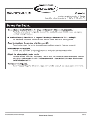
- 1. Gazebo Canopy Assembly OWNER’S MANUAL Gazebo Includes instructions for 10’ x 10’ Gazebo Gazebo Canopy Assembly Assembled exterior dimensions: 11’ 3”W. x 11’ 3”D. x 11’ 4”H. Before You Begin... • Consult your local authorities for any permits required to construct gazebo. Prior to the construction of your gazebo, check with the local building code official to review any required permits or building limitations. • A level and sturdy foundation is required before gazebo construction can begin. Site preparation information is available in this manual. Please read before building gazebo. • Read instructions thoroughly prior to assembly. This kit contains parts that can be damaged if assembled incorrectly or in the wrong sequence. • Please follow instructions. Suncast is not responsible for replacing parts lost or damaged due to incorrect assembly. • Check for all parts before you begin. Using the provided parts check list on pages 4 and 5, verify that you have all the parts required to construct your gazebo model. COMPLETE SITE PREPARATION AND FOUNDATION CONSTRUCTION BEFORE UNPACKING ALL PARTS. • Assistance is required. Due to the size of the parts, at least two people are required to handle, fit and secure gazebo components. © 2008 Suncast Corporation, Batavia, IL 0361057
- 2. Gazebo Canopy Assembly CAUTION • Gazebo not intended for use in extreme weather conditions. • Do not stand, sit, or store items on gazebo roof. • Handle carefully in extreme temperatures. • Repair or replace broken parts immediately. • Suncast is not responsible for damage caused by weather or misuse. • At regular intervals inspect your gazebo to make sure that assembly integrity has been maintained. • Periodically check that the location you have chosen to set your gazebo is still level. • Avoid excess heat from any auxiliary source. • Railing is not intended as a seat. • Any additional holes drilled into parts could cause unsafe conditions. • Gazebo is not intended to be enclosed. • Follow manufacturer safety instructions when using ladder. • Do not anchor to paver bricks. Foundation must be a solid surface. • Exercise caution using a lawn mower, edge trimmer or other yard equipment near gazebo. • Maximum weight that can be hung from Top Roof Rail: 20 lbs. • Do not hang objects from Bottom Roof Rail. • Do not hang objects from Facia Board. Top roof rail Bottom roof rail 2
- 3. Gazebo Canopy Assembly Gazebo Safety and Care • Wash gazebo with garden hose or mild detergent solution and soft cloth. Do not use a stiff brush or abrasive cleaner as that could damage gazebo. • Hot items, such as recently used grills, blowtorches, etc., must not be used in or near the gazebo. • Heavy articles should not be leaned against the post and rails, as this may cause panel distortion and permanent damage. • Keep roof clean of snow and leaves. Tools Needed for Installation 8’ 6’ 1/8” or Concrete Foundation Assembly Day Tips omplete site preparation and foundation construction before unpacking •C parts and beginning assembly. • ake care when removing PVC parts. Other parts are packed inside them. T • Do not attempt to assemble on a day with strong winds. • Do not attempt to assemble on days when temperature is below 32 degrees. • Set aside appropriate amount of time to completely assemble gazebo. • Make sure you have assistance nearby to lift and secure parts in place. • Wear light duty work gloves while assembling gazebo. • If you have questions on assembly, please call 800-846-2345. Note: This product contains parts that are used in different orientations to construct the gazebo. Please take note of the orientation of the parts shown throughout this instruction manual. Failure to follow instructions could result in damage to parts. Suncast is not responsible for replacing parts lost or damaged due to incorrect assembly. 3
- 4. Gazebo Canopy Assembly Parts A C 0101856A0 – Bottom upper shingle roof 0101852A1 – Bottom upper underside roof x8 x8 B 0101857A0 – Bottom lower shingle roof/0101853A1 – Bottom lower underside roof x8 Hardware J E G I 0210152 – Stainless steel screw x76 0101854A0 – Top upper 0101850A1 – Top upper 0440496 – Turnbuckle shingle roof underside roof x8 x8 K L F 0440496 – Cable clamp 0240049 – Screw cap x2 x44 0101855A0 – Top lower shingle roof/ M N 0101851A1 – Top lower underside roof x8 0510496 – 37.75’ Cable 0510498 – Roof railing plug Note: Parts D and H are pre-assembled with x64 parts B and F respectively. 4
- 5. Gazebo Canopy Assembly Parts R T S 0101848A1 Upper rafter U 0101846A0 connector Top cap 0630464 Upper roof rafter x8 V x8 0630470 Y Center hub spacer 0101847A1 x8 Bottom hub connector X 0101849A1 Lower rafter Z W hub connector x8 0630475 0101843A1 0630471 Dowel pin Post collar Roof support posts x16 x8 x8 BB 0630463 O P Q AA Lower roof rafter x8 EE CC DD 0630461 0630462 0630460 0630477 0101845A1 0101844A1 0630474 Left doorway Right doorway PVC post Steel post Lower roof end cap Upper roof end cap Roof weather strip PVC post PVC post x6 x8 x8 x8 x16 HH II GG FF 0630467 0630469 Lower roof rail Roof spindle x16 x136 JJ KK 0510499 0630466 0630472 0630468 Post hole Hand rail spindle Lower roof fascia Upper roof rail template x48 x7 x16 LL MM NN 0630465 0630476 0630473 Hand rail Doorway lower roof fascia Upper roof fascia x14 x8 5
- 6. Gazebo Canopy Assembly Site preparation and platform construction (Materials NOT supplied with Gazebo Kit) ote: Site preparation and platform construction and Support Post Installation steps may require professional N assistance to be installed correctly. Please read all manual steps thoroughly before starting this project. ote: Site preparation and platform construction are required for this gazebo. Placing the gazebo on the ground N without any type of foundation is not recommended. Suncast is not responsible for replacing parts damaged or property lost due to construction without a foundation or platform. Complete the site preparation and platform construction before unpacking parts. To prepare your gazebo site, follow the below steps: 1) Consult your local authorities for building codes and covenants before beginning foundation or erecting gazebo. 2) Consult your local building supply retailer to assist you in determining the best foundation or platform method for your application. The building supply retailer can also help you determine what anchoring hardware you will need once the foundation or platform method has been determined. Bring this manual with you to the retailer so they can see the scope of the project. 3) Before any digging, check with local utilities to determine location of buried cables, pipes, etc. 4) A 4 inch thick concrete slab is recommended as the foundation. - If a wood platform is chosen as the foundation, use exterior grade wood. Note: Do not erect gazebo on paver bricks. Foundation must be a solid surface. If you plan to erect the gazebo on an existing deck, consult local authorities for building codes and make sure that the structure is sound and can hold the additional weight of the gazebo (approx. 375 lbs.). Consult local building supply retailer to determine the best method and hardware for your application. 5) Preparing the building site: - The ground should slope away from the foundation area to provide drainage. - The foundation surface must be flat and level. - Follow local building codes for a proper vapor barrier. Ensure site allows room for your gazebo: 1) Square foundation should be 10’ 6” x 10’ 6”. 2) If an octagon foundation is wanted for your gazebo, consult your local building supply retailer to help you determine materials and hardware required. 3) Overall height (foundation to top of top cap) – 11’ 4”. 4) Overall base width (support post to support post) – 10’ 2.5”. 5) Overall roof width (rafter end to rafter end) – 11’ 3”. 6
- 7. Gazebo Canopy Assembly Support Post Installation 1 10’ 6” ” ’6 10 Ensure square foundation is 10’ 6” x 10’ 6”. Locate and mark center of foundation slab or deck. 2 3 115 ” Do orw ay Using center point and wire, draw a 115” diameter Determine doorway location and mark right circle. DO NOT use string (string will stretch causing doorway post. inaccurate measurements). 7
- 8. Gazebo Canopy Assembly 4 5 44” 44” x8 Measure 44” from the intersection of circle and chalk Double check markings to ensure there are 44” be- line to next post position. Measure directly from point tween each post location. to point, NOT along circle. Mark this spot. Do this eight times to identify all post locations. 6 7 115 ” x32 O B ZE GA OF TER N CE FF Snap all chalk lines so that all post locations have Using the post hole template, align with circle and straight lines (bisecting center of circle). chalk line for each of the eight post locations. Mark where drill holes are needed. Double check that circle diameter is still 115”. 8
- 9. Gazebo Canopy Assembly Note: Before drilling into foundation, check with local building supply retailer for best method and hardware for your application. 8a Concrete foundation 8b Wood foundation 5 2 2 1 x32 1 x32 x32 x32 Using a hammer drill, make holes for each post. Drill holes for each post. From underside of Then insert concrete lag anchors and four foundation, insert four full-threaded lag bolts and full-threaded studs. washers. 9 10 AA AA x8 x32 Ensure steel posts are in correct orientation. Bolt down all steel posts. Note: Ensure all steel posts are secured to foundation.
- 10. Gazebo Canopy Assembly Parts Pre-Assembly Note: To avoid scratching finish in steps where parts are placed upside down, place parts on smooth surface. Flat- ten cardboard from carton to create a smooth surface. 11 12 A A B B x4 x4 Insert A into the corresponding slots in B. Slide A and lock into place in B. Note:Ensure that preassembled B is assembled properly. 13 14 C Repeat steps 11-13 A for seven remaining bottom roof panels. B x3 Snap C into A and B to form a single bottom roof panel. 10
- 11. Gazebo Canopy Assembly 15 16 E E F F x2 x2 Insert E into the corresponding slots in F. Slide E and lock into place in F. Note:Ensure preassembled F is assembled properly. 17 18 G E Repeat steps 15-17 for seven remaining top roof panels. F x2 Snap G into E and F to form a single top roof panel. 11
- 12. Gazebo Canopy Assembly 19 20 LL GG LL Insert eight hand rail spindles into square hand rail Place another hand rail (matching spindles with holes. square holes). 21 22 Repeat steps 19-20 for six remaining hand rails. Optional: After assembled, run II a band of low tack tape around assembly. This will help hold HH rails together until they are used again. Insert eleven roof spindles into square lower roof rail holes. 12
- 13. Gazebo Canopy Assembly 23 24 Repeat steps 22-23 HH for seven remaining bottom roof railings. Optional: After assembled, run a band of low tack tape around assembly. This will help hold rails together until they are used again. Place another lower roof rail (matching spindles with square holes). Note:Match orientation of bottom of roof rail. 25 26 KK II KK Insert six roof spindles into upper roof rail. Place another upper roof rail (matching roof spindles with square holes). Note:Match orientation of bottom roof rail. 13
- 14. Gazebo Canopy Assembly 27 28 Repeat steps 25-26 Y for seven remaining upper roof railings. Optional: After assembled, run a band of low tack tape around BB assembly. This will help hold rails together until they are used again. Snap lower rafter hub connector into place at angled end of lower roof rafter. 29 30 U X T S BB 1 2 Snap center hub spacer into lower roof rafter hub Snap upper rafter connector into place on angled side connector. Add roof support post to lower roof rafter. of upper roof rafter. 14
- 15. Gazebo Canopy Assembly 31 32 x2 J 2 L 1 Snap upper rafter connector onto center hub spacer. Secure roof support posts to upper and lower roof Slide upper roof rafter into place over roof support post rafters using screws and screw caps. on lower roof rafter. Note: Make sure you go through the roof support post. 33 Before starting Repeat steps 28-32 gazebo assembly, for seven remaining allow adequate time roof rafters. (about 6 hours). 15
- 16. Gazebo Assembly Gazebo Canopy Assembly Note: Verify post assembly orientation (see Step 9). 34 35 Q O P x6 Inside AA of gazebo Do orw ay Place left and right doorway PVC posts over steel Place the six other PVC posts over remaining steel posts, making sure that hand rail holes face away from posts. doorway. 36 37 1-1/2” J 1” x16 x16 Predrill two 1/8” holes through PVC posts and into Secure all posts with screws in pilot holes. steel posts (both flat sides of steel posts). Make sure to take into account the “Z” shape of steel post when drilling hole on opposite side of PVC posts. 16
- 17. Gazebo Canopy Assembly 38 39 For steps 40-45 have one person stand on an 8’ ladder in the middle of foundation and another person on a 6’ ladder next to the PVC post you are working with. The extra W height will make it easier to x8 assemble parts. Slide one post collar over each post. 40 41 Z Z Slide one rafter assembly up through PVC post notch Slide opposite rafter assembly up through PVC post notch and into postion. Secure with two dowel pins. (If and into position. Secure with two dowel pins. (If necessary, necessary, use a rubber mallet to ensure tips of dowel use a rubber mallet to ensure tips of dowel pins exit other pins exit other side of PVC post.) The person on 8’ side of PVC post.) Make sure to support rafters ather ladder will need to support rafter assembly. assembling. 17
- 18. Gazebo Canopy Assembly 42 43 Repeat steps 40-42 V for two perpendicular rafter assemblies. Snap bottom hub connector onto rafter connectors. Note:The hub connector will only engage on alternating rafter assemblies. 44 45 Repeat step 44 for remaining three rafter assemblies. Z Lift fifth rafter assembly 6” above installed rafters. Slide connector down into place along grooves. Secure lower end of rafter with two dowel pins. (If necessary, use a rubber mallet to ensure tips of pins exit other side of PVC post). 18
- 19. Gazebo Canopy Assembly 46 47 M I 1 K M 2 3 Thread turnbuckle cable through the upper most Loop cable through turnbuckle eyelet. Put clamp on dowel pins, between posts and rafters (to stabilize cable. Use wrench to tighten nuts. assembly). 48 49 K 1 M 1 3 2 I 2 I Put clamp on remaining end of cable. Use wrench to Standing on a ladder, push bottom hub connector up. tighten nuts. Place loop cable around turnbuckle hook. Tighten turnbuckle to take up slack. DO NOT FULLY TIGHTEN TURNBUCKLE. 1
- 20. Gazebo Canopy Assembly 50 51 R 1 111” Check that the distance from the bottom hub Using a rubber mallet, attach top cap onto upper roof connector to the floor is 111”. If necessary, adjust rafter connectors. turnbuckle. DO NOT FULLY TIGHTEN TURNBUCKLE. 52 53 NN Repeat step 52 for remaining seven upper roof fascia boards. Insert one upper roof fascia board between upper roof rafters. 20
- 21. Gazebo Canopy Assembly 54 55 1 2 J Take one pre-assembled upper roof panel and slide Predrill 1/8” holes and screw the upper roof panel to over fascia boards along rafter groove and under top the fascia board. cap. Make sure roof panel is fully engaged on inside of fascia boards. 56 57 Repeat steps 53-55 for remaining seven 1 top roof fascia boards. EE DO NOT proceed to next step until step 56 is complete. 2 Snap one roof weather strip 3/4 of the way up on upper roof rafter. Slide up under top cap until flush with end of upper roof rafters. 21
- 22. Gazebo Canopy Assembly 58 59 Repeat step 57 for remaining seven weather strips. DD x8 Snap one upper roof end cap onto end of each upper roof rafter. 60 61 Repeat step 60 for remaining seven upper roof railings. x8 Insert one pre-assembled upper roof railing between roof support posts. (Ensure rails are centered.) 22
- 23. Gazebo Canopy Assembly 62 63 MM x32 N Insert roof railing plugs into pre-drilled holes (top and Insert doorway lower roof fascia board into place bottom) of upper roof railings (four per rail). between doorway posts. 64 65 1 2 J Take one pre-assembled lower roof panel and slide Predrill 1/8” holes and screw the lower roof panel to over lower fascia board along the rafter groove. Make the lower fascia board. sure lower roof panel is fully engaged on inside of lower fascia boards. 23
- 24. Gazebo Canopy Assembly 66 67 Repeat steps 63-65 for remaining seven lower roof fascia boards and lower roof panels. 1 EE DO NOT proceed to next step until step 66 is complete. 2 Snap one roof weather strip 3/4 of the way up on lower roof rafter. Slide up until flush. 68 69 Repeat step 67 for remaining seven weather strips. CC x8 Snap one lower roof end caps onto lower rafters. Repeat for remaining seven lower roof rafters. 24
- 25. Gazebo Canopy Assembly 70 71 Repeat step 70 for remaining seven lower roof rails. Insert one pre-assembled lower roof railing between each roof support post. (Ensure rails are centered.) 72 73 N I 1 x32 2 Insert roof railing plugs into pre-drilled holes (top and If necessary, finish tightening turnbuckle cable to bottom) of lower roof railings. (Four per rail). secure complete upper assembly. Using a wire cutter or hacksaw, cut off excess cable beyond clamp. 25
- 26. Gazebo Canopy Assembly 74 75 Repeat step 74 for remaining six hand rails. Starting at one side of the doorway, insert one side of one preassembled hand rail into notches in PVC post. Insert remaining side of hand rail and center between PVC posts. 76 77 L J x2 x2 L J Center hand rail and make sure spindles are vertical. Center hand rail and make sure spindles are vertical. Secure lower handrails using two screws and screw caps Secure upper handrails using two screws and screw caps per section (top side of bottom hand rail—one per side). per section (underside of top hand rail—one per side). Place screws and screw caps as close to PVC post as Place screws and screw caps as close to PVC post as possible where the hand rail meets the PVC post. possible where the hand rail meets the PVC post. 26
- 27. Gazebo Canopy Assembly 78 Repeat steps 76-77 for remaining hand rails. Complete. 27
- 28. Gazebo Canopy Assembly Warranty Suncast® Corporation, 701 North Kirk Road, Batavia, Illinois 60510 (Manufacturer) warrants to the original purchas- er only that the enclosed product is free from material and workmanship defects under normal, household use at time of purchase. Defective product or part must be returned, freight prepaid, to the Manufacturer’s address (Atten- tion: Parts Department) along with proof of purchase. Upon receipt of the aforesaid, the defective product or part will be repaired or replaced at the option of the Manufacturer without charge to the original purchaser and returned to the customer freight collect. This limited warranty does not apply to damage resulting from accident, neglect, misuse, commercial use, alteration, operation not in accordance with instruction or repairs made or attempted by unauthorized persons. This limited warranty applies only to the product enclosed and does not apply to accessory parts. THE MANUFACTURER’S LIABILITY HEREUNDER IS LIMITED SOLELY TO THE REPAIR OR REPLACEMENT OF THE DEFECTIVE PRODUCT OR PART AND THE MANUFACTURER SHALL IN NO EVENT BE LIABLE FOR ANY INCIDENTAL OR CONSEQUENTIAL DAMAGES WHICH MAY RESULT FROM ANY DEFECT IN MATERIAL OR WORKMANSHIP OR FROM THE BREACH OF ANY EXPRESS OR IMPLIED WARRANTY. Some states do not allow the exclusion or limitation of incidental or consequential damages, or a limitation of how long an implied warranty lasts, so the above limitations may not apply to you. This warranty gives you specific legal rights, and you may have other rights which may vary from state to state. Factory Repairs Repair service and assembly assistance are available direct from the factory, not from the place of purchase. If this product requires repair, please call or write us. Warranty repair parts are sent out free of charge. If the product is out of warranty, we will inform you of the charges prior to sending out the parts. VISA and MasterCard are accepted on phone orders. For assembly or replacement parts information: Replacement Parts Suncast Corporation 701 North Kirk Road Batavia, IL 60510 Outside Illinois, but within North America 800-846-2345 24 hour service / 7 days a week Within Illinois, or outside North America 630-87-2050 visit: www.suncast.com email: parts@suncast.com PATENTS Patents pending.