
Empfohlen
Weitere ähnliche Inhalte
Was ist angesagt?
Was ist angesagt? (20)
Ähnlich wie JK FLIPFLOP WITH TOGGLE
Ähnlich wie JK FLIPFLOP WITH TOGGLE (20)
Mehr von Fredrick Kendrick
Mehr von Fredrick Kendrick (20)
JK FLIPFLOP WITH TOGGLE
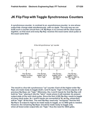
- 1. Fredrick Kendrick Electronic Engineering Dept. ITT Technical ET1220 JK Flip Flop with Toggle Synchronous Counters A synchronous counter, in contrast to an asynchronous counter, is one whose output bits change state simultaneously, with no ripple. The only way we can build such a counter circuit from J-K flip-flops is to connect all the clock inputs together, so that each and every flip-flop receives the exact same clock pulse at the exact same time: The result is a four-bit synchronous "up" counter. Each of the higher-order flip- flops are made ready to toggle (both J and K inputs "high") if the Q outputs of all previous flip-flops are "high." Otherwise, the J and K inputs for that flip-flop will both be "low," placing it into the "latch" mode where it will maintain its present output state at the next clock pulse. Since the first (LSB) flip-flop needs to toggle at every clock pulse, its J and K inputs are connected to Vcc or Vdd, where they will be "high" all the time. The next flip-flop need only "recognize" that the first flip-flop's Q output is high to be made ready to toggle, so no AND gate is needed. However, the remaining flip-flops should be made ready to toggle only when all lower-order output bits are "high," thus the need for AND gates.
- 2. Fredrick Kendrick Electronic Engineering Dept. ITT Technical ET1220 To make a synchronous "down" counter, we need to build the circuit to recognize the appropriate bit patterns predicting each toggle state while counting down. Not surprisingly, when we examine the four-bit binary count sequence, we see that all preceding bits are "low" prior to a toggle (following the sequence from bottom to top): Since each J-K flip-flop comes equipped with a Q' output as well as a Q output, we can use the Q' outputs to enable the toggle mode on each succeeding flip- flop, being that each Q' will be "high" every time that the respective Q is "low:" Note how the least significant bit (LSB) toggles between 0 and 1 for every step in the count sequence, while each succeeding bit toggles at one-half the frequency of the one before it. The most significant bit (MSB) only toggles once during the entire sixteen-step count sequence: at the transition between 7 (0111) and 8 (1000). If we wanted to design a digital circuit to "count" in four-bit binary, all we would have to do is design a series of frequency divider circuits, each circuit dividing the frequency of a square-wave pulse by a factor of 2:
- 3. Fredrick Kendrick Electronic Engineering Dept. ITT Technical ET1220 The NOTES were taken from Don Heller’s Class on 2/13th & 20th/2015. Research was put into the understanding of this system from your board work. “Thank You for taking the time to show detail.”