3. Technical Reference - 6, 12, 18, 24 & 30 inch lengths -
Total # of (F) Holes: 4
1: REF
Total # of (F) Holes: 8
Total # of (F) Holes: 10
Total # of (F) Holes: 14
1: REF
Total # of (F) Holes: 6
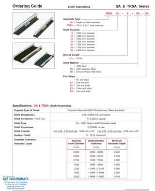
Dimensions
6
1 4
12
18
24
6 5 6
1
6 5 5
5
4 6
(1)
(1)
(1)
(1)
B E
F (hole size)
D
C
A
G
See pages 64 & 65
for end machining options
and end stops.
(inches)
SA Series
Sold & Serviced By:
ELECTROMATE
Toll Free Phone (877) SERVO98
Toll Free Fax (877) SERV099
www.electromate.com
sales@electromate.com
Specifications subject to change without notice
2
30
6 5 5 6
4
(1)
1 1: REF
1 1: REF
1 1: REF
Footnotes:
(1)
Shaft supports come in 6, 12, 18 and 24 inch segments. The mounting hole location linear tolerance is +/- .010 inches noncumulative per segment. These
supports are not one piece for lengths over 24 inches. The mounting hole linear tolerance is +/- .015 inches cumulative from one support segment to the next.
5. Technical Reference - 36, 42, 48, 54 & 60 inch lengths -
Total # of (F) Holes: 16
1 1: REF
Total # of (F) Holes: 18
1 1: REF
Total # of (F) Holes: 20
36
6 5 5 6
4 6
(1)
42
6 5 5 6 6 5 5
(1)
48
6 5 5 6 6 5 5 6
(1)
SA Series
Sold & Serviced By:
ELECTROMATE
Toll Free Phone (877) SERVO98
Toll Free Fax (877) SERV099
www.electromate.com
sales@electromate.com
Specifications subject to change without notice
1 1: REF
54
6 5 5 6 6 5 5 6
4
Total # of (F) Holes: 24 (1)
1 1: REF
60
1 1: REF
6 5 5 6 6 5 5 6 4 6
Total # of (F) Holes: 26 (1)
2
2
2
2
2
2
2
B E
F (hole size)
D
C
A
G
See pages 64 & 65
for end machining options
and end stops.
Dimensions
(inches)
Footnotes:
(1)
Shaft supports come in 6, 12, 18 and 24 inch segments. The mounting hole location linear tolerance is +/- .010 inches noncumulative per segment. These
supports are not one piece for lengths over 24 inches. The mounting hole linear tolerance is +/- .015 inches cumulative from one support segment to the next.
7. Technical Reference - 66, 72, 84, 96 & 108 inch lengths -
66
B E
D
G
C
A
6 5 5 6 6 5 5 6
6 5 5
See pages 64 & 65
for end machining options
and end stops.
F (hole size)
Total # of (F) Holes: 28 (1)
1 1: REF
72
6
Total # of (F) Holes: 30 (1)
SA Series
1 1: REF
Specifications subject to change without notice
6
2
6 5 5 6 6 5 5 6 6 5 5
1 1: REF
84
Total # of (F) Holes: 36 (1)
4
1 1: REF
6 5 5 6
6 5 5 6 6 5 5 6 6 5 5 6
96
Total # of (F) Holes: 40 (1)
6
6 5 5 6 6 5 5 6 6 5 5 6
108
Total # of (F) Holes: 46(1)
Hole Pattern Repeats 4
6 5 5 6 6 5 5 6
2
2
2
2
2 2
2
2 2
1 1: REF
2 2 2
Dimensions
(inches)
Footnotes:
(1)
Shaft supports come in 6, 12, 18 and 24 inch segments. The mounting hole location linear tolerance is +/- .010 inches noncumulative per segment. These
supports are not one piece for lengths over 24 inches. The mounting hole linear tolerance is +/- .015 inches cumulative from one support segment to the next.
9. Technical Reference - 120, 144, 168 & 196 inch lengths -
B E
See pages 64 & 65
for end machining options
and end stops.
F (hole size)
G
C
Hole Pattern Repeats
120
SA Series
Total # of (F) Holes: 50(1)
(1)
D
A
Dimensions
(inches)
1 1: REF
Specifications subject to change without notice
6 5 5 6 6 5 5 6 6 5 5 6
Total # of (F) Holes: 60(1)
Total # of (F) Holes: 70(1)
Total # of (F) Holes: 80(2 2 2
Hole Pattern Repeats
144
1 6 5 5 6 6 5 5 6 6 5 5 6 1: REF
2 2 2
Hole Pattern Repeats
168
1 6 5 5 6 6 5 5 6 6 5 5 6 1: REF
2 2 2
Hole Pattern Repeats
192
1 6 5 5 6 6 5 5 6 6 5 5 6 1: REF
2 2 2
Footnotes:
(1)
Shaft supports come in 6, 12, 18 and 24 inch segments. The mounting hole location linear tolerance is +/- .010 inches noncumulative per segment. These
supports are not one piece for lengths over 24 inches. The mounting hole linear tolerance is +/- .015 inches cumulative from one support segment to the next.
Sold & Serviced By:
ELECTROMATE
Toll Free Phone (877) SERVO98
Toll Free Fax (877) SERV099
www.electromate.com
sales@electromate.com
10. Reduced Diameters, End Stops, Coaxial & Radial Holes
Reduced diameters, end stops, coaxial & radial holes can be provided on any shaft or shaft assembly. The standard tol-erance
for a reduced diameter is +/- .001 inches, while the concentricity is .002 inches TIR. The shaft may be annealed and
soft around the shaft circumference adjacent to the reduced diameter. Coaxial holes are drilled and tapped in the center of
the shaft ends and radial holes can be drilled and tapped as desired. The concentricity of the holes will be .005 inches TIR.
Reduced Diameters Coaxial & Radial Holes
Butted, Doweled, and Threaded & Ground Joints
Standard shaft assemblies cannot be combined to create longer lengths, as the rolling elements of re-circulating linear
bearings will "jam" at the joined ends due to the shaft chamfer. For those long length or custom applications, LINTECH
provides several options for joining shaft assemblies. Butted, doweled, threaded, and ground joints are available with all shaft
lengths and diameters. All of these options will have the standard chamfer removed from the shaft ends. The concentricity of
doweled joints is < .001 inches, while the concentricity of butted joints will depend upon the user mounting surface.
Butt Joint Dowel Joint
Threaded and Ground Joint
Options
Sold & Serviced By:
Specifications subject to change without notice
End Stops
ELECTROMATE
Toll Free Phone (877) SERVO98
Toll Free Fax (877) SERV099
www.electromate.com
sales@electromate.com
11. Options
Custom Shaft Assembly Lengths & Widths
Custom shaft assembly lengths and widths (shorter and longer) not shown in this catalog can be provided upon request.
Metric Shaft Assemblies
Metric shaft assemblies can be provided upon request by combining SM shafting with the LSRS or ARS shaft supports.
Chrome Plated Shafts
For applications in high moisture, high humidity, clean room, or highly corrosive environments, chrome plating of the
shafts will offer superior resistance to corrosion. The process uniformly deposits dense, hard, high Chromium alloy onto the
shaft, and has a Rockwell C hardness value of 67-72. This process also conforms to MIL Spec: (MIL-C-23422). The chrome
plating bonds to the parent steel and will not crack or peel off under the high point loading of the balls on the shaft. This
chrome plating process differs from normal hard chrome which just lays on the surface of the part plated.
Shaft Support Finishes
The standard anodized finish of the aluminum shaft supports can be changed to meet the requirements needed for
operation in clean rooms, food processing facilities, highly corrosive environments, or for different appearances. The standard
enamel finish of the steel shaft supports can also be changed. Available options are clear or color anodized, chem-film, nickel
plated, chrome plated, different oxide color finishes, or painted per customer specifications.
End stops are available for every shaft assembly size and length. They provide a mechanical stop for the linear bearings
to prevent them from sliding off the end of the shaft. The shaft ends are drilled, tapped, and a washer is installed using a cap
screw and lock washer.
Specifications subject to change without notice
(see model #) (inches) A B C D
Cap Screw
Number of
End Stops
Nominal
Shaft Dia.
Dimensions
(inches)
(1)
0.500
(2)
E1, E2, E3, E4 .375 .062 1.125
E1, E2, E3, E4 0.625 .453 .062 1.375
E1, E2, E3, E4 0.750 .532 .062 1.625
E1, E2, E3, E4 1.000 .656 .109 1.812
E1, E2, E3, E4 1.250 .750 .125 2.250
E1, E2, E3, E4 1.500 .750 .125 2.625
E1, E2, E3, E4 2.000 .750 .125 3.250
B
A
C
D
Shaft Support End Stops
1/4
5/16
3/8
7/16
1/2
1/2
1/2
Footnotes:
Cap screw for end stops have black oxide finish. End stop & cap screw lock washers are Cadmium plated (QQ-P-416 Type II).
When only Specifying one end stop (E1) for SA, or two end stops for the TRSA (E2), the end stops will be installed on the left
hand end of the assembly, as depicted by the above drawing, unless specified otherwise.
(1)
(2)
Sold & Serviced By:
ELECTROMATE
Toll Free Phone (877) SERVO98
Toll Free Fax (877) SERV099
www.electromate.com
sales@electromate.com